
Manual
Page 3
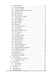
Table of Contents Box Contents...6 MW50-SV0 Motherboard Layout 7 Block Diagram...10 Chapter 1 Hardware Installation 11 1-1 Installation Precautions 11 1-2 Product Specifications 12 1-3 Installing the CPU and CPU Cooler 14...Four Channel Memory Configuration 18 1-4-2 Installing a Memory 19 1-4-3 DIMM Population Table 19 1-5 Back Panel Connectors 20 1-6 Internal Connectors 21 1-7 Jumper Settings 32 Chapter 2 BIOS Setup 37 2-1 The Main Menu 39 2-2 Advanced Menu 41 2-2-1 Serial Port Console Redirection 42 2-2-2 PCI Subsystem Settings 46 2-2-2-1 PCI Express Settings 48 2-2-2-2 PCI Hot...
Table of Contents Box Contents...6 MW50-SV0 Motherboard Layout 7 Block Diagram...10 Chapter 1 Hardware Installation 11 1-1 Installation Precautions 11 1-2 Product Specifications 12 1-3 Installing the CPU and CPU Cooler 14...Four Channel Memory Configuration 18 1-4-2 Installing a Memory 19 1-4-3 DIMM Population Table 19 1-5 Back Panel Connectors 20 1-6 Internal Connectors 21 1-7 Jumper Settings 32 Chapter 2 BIOS Setup 37 2-1 The Main Menu 39 2-2 Advanced Menu 41 2-2-1 Serial Port Console Redirection 42 2-2-2 PCI Subsystem Settings 46 2-2-2-1 PCI Express Settings 48 2-2-2-2 PCI Hot...
Manual
Page 4
... Log Settings 114 2-4-2 View Smbios Event Log 115 2-5 Security Menu 116 2-5-1 Secure Boot menu 117 2-5-1-1 Key Management 118 2-6 Boot Menu...120 2-7 Save & Exit Menu 122 2-8 BIOS POST Codes 124 - 4 -
... Log Settings 114 2-4-2 View Smbios Event Log 115 2-5 Security Menu 116 2-5-1 Secure Boot menu 117 2-5-1-1 Key Management 118 2-6 Boot Menu...120 2-7 Save & Exit Menu 122 2-8 BIOS POST Codes 124 - 4 -

Manual
Page 5
2-9 BIOS POST Beep code 128 2-9-1 PEI Beep Codes...128 2-9-2 DEX Beep Codes 128 2-10 BIOS Recovery Instruction 129 Chapter 3 Appendix...130 3-1 Regulatory Statements 130 - 5 -
2-9 BIOS POST Beep code 128 2-9-1 PEI Beep Codes...128 2-9-2 DEX Beep Codes 128 2-10 BIOS Recovery Instruction 129 Chapter 3 Appendix...130 3-1 Regulatory Statements 130 - 5 -
Manual
Page 9
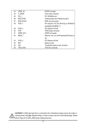
... SPDIF_OUT 52 MEZZ_1 53 PCIE_4 54 BAT 55 TBT 56 CPU0_FAN S/PDIF in header Front audio connector PCI 32/33MHz slot Clearing Supervisor Password jumper BIOS recovery jumper PCI Express x16 slot (Running at x8/Shared bandwidth with MEZZ_1) PCI Express x16 slot TPM module connector S/PDIF out header Mezzine slot...
... SPDIF_OUT 52 MEZZ_1 53 PCIE_4 54 BAT 55 TBT 56 CPU0_FAN S/PDIF in header Front audio connector PCI 32/33MHz slot Clearing Supervisor Password jumper BIOS recovery jumper PCI Express x16 slot (Running at x8/Shared bandwidth with MEZZ_1) PCI Express x16 slot TPM module connector S/PDIF out header Mezzine slot...
Manual
Page 13
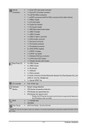
Internal Connectors Rear Panel I/O I/O Controller Hardware Monitor BIOS Form Factor ŠŠ 1 x 24-pin ATX main power connector ŠŠ 1 x 8-pin ATX 12V power connector ŠŠ 13 x SATA3 6Gb/s connectors ŠŠ 1 x ... control function is supported will depend on the CPU/system cooler you install. ŠŠ 1 x 128 Mbit flash ŠŠ AMI BIOS ŠŠ ATX Form Factor; 12 inch x 9.6 inch * GIGABYTE reserves the right to make any changes to the product specifications and product-related information without prior notice. - 13 - Hardware Installation
Internal Connectors Rear Panel I/O I/O Controller Hardware Monitor BIOS Form Factor ŠŠ 1 x 24-pin ATX main power connector ŠŠ 1 x 8-pin ATX 12V power connector ŠŠ 13 x SATA3 6Gb/s connectors ŠŠ 1 x ... control function is supported will depend on the CPU/system cooler you install. ŠŠ 1 x 128 Mbit flash ŠŠ AMI BIOS ŠŠ ATX Form Factor; 12 inch x 9.6 inch * GIGABYTE reserves the right to make any changes to the product specifications and product-related information without prior notice. - 13 - Hardware Installation
Manual
Page 18
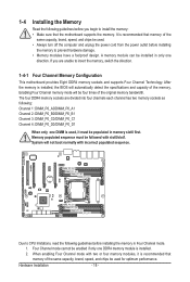
... limitations, read the following : Channel 1: DIMM_P0_A0/DIMM_P0_A1 Channel 2: DIMM_P0_B0/DIMM_P0_B1 Channel 3: DIMM_P0_C0/DIMM_P0_C1 Channel 4: DIMM_P0_D0/DIMM_P0_D1 When only one DDR4 memory module is installed, the BIOS will automatically detect the specifications and capacity of the original memory bandwidth. After the memory is installed. 2. Enabling Four Channel memory mode will not boot...
... limitations, read the following : Channel 1: DIMM_P0_A0/DIMM_P0_A1 Channel 2: DIMM_P0_B0/DIMM_P0_B1 Channel 3: DIMM_P0_C0/DIMM_P0_C1 Channel 4: DIMM_P0_D0/DIMM_P0_D1 When only one DDR4 memory module is installed, the BIOS will automatically detect the specifications and capacity of the original memory bandwidth. After the memory is installed. 2. Enabling Four Channel memory mode will not boot...
Manual
Page 31
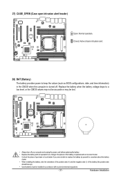
... open intrusion alert header) Open: Normal operation. Closed: Active chassis intrustion alert. 28) BAT (Battery) The battery provides power to keep the values (such as BIOS configurations, date, and time information) in the CMOS when the computer is replaced with an incorrect model. • Contact the place of the battery (the...
... open intrusion alert header) Open: Normal operation. Closed: Active chassis intrustion alert. 28) BAT (Battery) The battery provides power to keep the values (such as BIOS configurations, date, and time information) in the CMOS when the computer is replaced with an incorrect model. • Contact the place of the battery (the...
Manual
Page 33
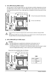
... drive is connected to the motherboard, please ensure the jumper is closed and set to reduce any risk of hard disk damage. date information and BIOS configurations) and reset the CMOS values to touch the two pins for a few seconds. 1 1-2 Close: Normal operation (Default setting) 1 2-3 Close: Clear CMOS data. SATA_DOM4 1 Pin...
... drive is connected to the motherboard, please ensure the jumper is closed and set to reduce any risk of hard disk damage. date information and BIOS configurations) and reset the CMOS values to touch the two pins for a few seconds. 1 1-2 Close: Normal operation (Default setting) 1 2-3 Close: Clear CMOS data. SATA_DOM4 1 Pin...
Manual
Page 35
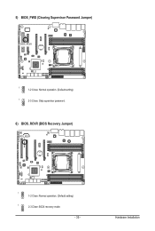
Hardware Installation 5) BIOS_PWD (Clearing Supervisor Password Jumper) BIOS_RCVR 1 1-2 Close: Normal operation. (Default setting) 1 2-3 Close: Skip supervisor password. 6) BIOS_RCVR (BIOS Recovery Jumper) BIOS_RCVR 1 1-2 Close: Normal operation. (Default setting) 1 2-3 Close: BIOS recovery mode. - 35 -
Hardware Installation 5) BIOS_PWD (Clearing Supervisor Password Jumper) BIOS_RCVR 1 1-2 Close: Normal operation. (Default setting) 1 2-3 Close: Skip supervisor password. 6) BIOS_RCVR (BIOS Recovery Jumper) BIOS_RCVR 1 1-2 Close: Normal operation. (Default setting) 1 2-3 Close: BIOS recovery mode. - 35 -

Manual
Page 37
... of the battery/clearing CMOS jumper in Chapter 1 for the current submenus Save all the changes and exit the BIOS Setup program - 37 - BIOS Setup To access the BIOS Setup program, press the key during system startup, saving system parameters and loading operating system, etc. Its major ...conducting the Power-On Self-Test (POST) during the POST when the power is turned on. • BIOS flashing is potentially risky, if you don't flash the BIOS. When the power is recommended that allows the user to modify basic system configuration settings or to select an...
... of the battery/clearing CMOS jumper in Chapter 1 for the current submenus Save all the changes and exit the BIOS Setup program - 37 - BIOS Setup To access the BIOS Setup program, press the key during system startup, saving system parameters and loading operating system, etc. Its major ...conducting the Power-On Self-Test (POST) during the POST when the power is turned on. • BIOS flashing is potentially risky, if you don't flash the BIOS. When the power is recommended that allows the user to modify basic system configuration settings or to select an...
Manual
Page 38
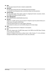
.... Boot This setup page provides items for configuring the function of boot sequence. Exit Save all the changes made in the BIOS Setup program to make changes in effect. Main This setup page includes all the items in standard compatible... BIOS. Advanced This setup page includes all the items of AMI BIOS special enhanced features. (ex: Auto detect fan and temperature status, automatically configure hard disk parameters.) Intel RC Setup...
.... Boot This setup page provides items for configuring the function of boot sequence. Exit Save all the changes made in the BIOS Setup program to make changes in effect. Main This setup page includes all the items in standard compatible... BIOS. Advanced This setup page includes all the items of AMI BIOS special enhanced features. (ex: Auto detect fan and temperature status, automatically configure hard disk parameters.) Intel RC Setup...

Manual
Page 39
... shown below) appears on the bottom line of the submenu. • When the system is displayed on the screen. Press to its defaults. • The BIOS Setup menus described in this chapter are for each item is in a submenu, press to accept or enter other sub-menu. Help for reference only... and may differ by BIOS version. - 39 - Submenu Help While in the Item Help block on the right side of the Main Menu. BIOS Setup Use arrow keys to move among the items and press to display a help screen.
... shown below) appears on the bottom line of the submenu. • When the system is displayed on the screen. Press to its defaults. • The BIOS Setup menus described in this chapter are for each item is in a submenu, press to accept or enter other sub-menu. Help for reference only... and may differ by BIOS version. - 39 - Submenu Help While in the Item Help block on the right side of the Main Menu. BIOS Setup Use arrow keys to move among the items and press to display a help screen.
Manual
Page 40
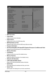
...MAC address information. Memory Frequency Display the frequency information of the BIOS setup utility. Porject Version Display version number of the installed memory. BIOS Build Date and Time Displays the date and time when the BIOS setup utility was created. year format. System Time Set the... system time following the weekday-month-day- BIOS Information Porject Name Display the project name information...
...MAC address information. Memory Frequency Display the frequency information of the BIOS setup utility. Porject Version Display version number of the installed memory. BIOS Build Date and Time Displays the date and time when the BIOS setup utility was created. year format. System Time Set the... system time following the weekday-month-day- BIOS Information Porject Name Display the project name information...
Manual
Page 41
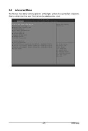
Select a submenu item, then press Enter to access the related submenu screen. - 41 - BIOS Setup 2-2 Advanced Menu The Advanced menu display submenu options for configuring the function of various hardware components.
Select a submenu item, then press Enter to access the related submenu screen. - 41 - BIOS Setup 2-2 Advanced Menu The Advanced menu display submenu options for configuring the function of various hardware components.

Manual
Page 44
...: parity bit is None. Communication with the data bits to enable console redirection for console redirection. Resolution 100x31 (Note) Enables or disables extended terminal resolution. BIOS Setup - 44 - COM1/COM2/Serial Over LAN Console Redirection Settings Console Redirection (Note) Select whether to detect some transmission errors. Bits per second Select the...
...: parity bit is None. Communication with the data bits to enable console redirection for console redirection. Resolution 100x31 (Note) Enables or disables extended terminal resolution. BIOS Setup - 44 - COM1/COM2/Serial Over LAN Console Redirection Settings Console Redirection (Note) Select whether to detect some transmission errors. Bits per second Select the...

Manual
Page 45
... VT100. Default setting is 80x24. Putty KeyPad (Note) Select function FunctionKey and KeyPad on Putty. Options available: VT100/LINUX/XTERMR6/SCO/ESCN/VT400. Redirection After BIOS POST (Note) This option allows user to enable console redirection after O.S has loaded...
... VT100. Default setting is 80x24. Putty KeyPad (Note) Select function FunctionKey and KeyPad on Putty. Options available: VT100/LINUX/XTERMR6/SCO/ESCN/VT400. Redirection After BIOS POST (Note) This option allows user to enable console redirection after O.S has loaded...
Manual
Page 46
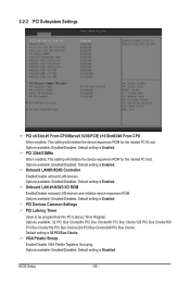
... 32bit/33MHz When enabled, This setting will initialize the device expansion ROM for the related PCI slot. Options available: Enabled/Disabled. Default setting is Enabled. BIOS Setup - 46 - Default setting is Enabled. Options available: Enabled/Disabled. PCI Devices Common Settings PCI Latency Timer Value to be programmed into PCI Latency Timer...
... 32bit/33MHz When enabled, This setting will initialize the device expansion ROM for the related PCI slot. Options available: Enabled/Disabled. Default setting is Enabled. BIOS Setup - 46 - Default setting is Enabled. Options available: Enabled/Disabled. PCI Devices Common Settings PCI Latency Timer Value to be programmed into PCI Latency Timer...

Manual
Page 47
Default setting is Disabled. Default setting is Disabled. SR-IOV Support If system has SR-IOV capable PCIe Devices, this option enables or disables Single Root IO Virtualization Support. PCI Express Settings Press [Enter] for configuration of advanced items. PCI Hot-Plug Settings Press [Enter] for configuration of advanced items. - 47 - BIOS Setup Options available: Enabled/Disabled. Above 4G Decoding Enable/Disable Above 4G Decoding. Options available: Enabled/Disabled.
Default setting is Disabled. Default setting is Disabled. SR-IOV Support If system has SR-IOV capable PCIe Devices, this option enables or disables Single Root IO Virtualization Support. PCI Express Settings Press [Enter] for configuration of advanced items. PCI Hot-Plug Settings Press [Enter] for configuration of advanced items. - 47 - BIOS Setup Options available: Enabled/Disabled. Above 4G Decoding Enable/Disable Above 4G Decoding. Options available: Enabled/Disabled.
Manual
Page 48
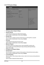
...allow device to select the value. Default setting is Disabled. Extended Tag Wnen this feature is enabled, the system will allow system BIOS to use 8-bit Tag field as a requester. Options available: Enabled/Disabled. Default setting is Enabled. No Snoop Enable/Disable PCI ...Express Device No Snoop option. Link Training Retry Define the number of Extended Synchronization patterns. BIOS Setup - 48 - Options available: Enabled/Disabled. Maximum Playload Set maximum playload for PCI Express Device or allow generation of Retry ...
...allow device to select the value. Default setting is Disabled. Extended Tag Wnen this feature is enabled, the system will allow system BIOS to use 8-bit Tag field as a requester. Options available: Enabled/Disabled. Default setting is Enabled. No Snoop Enable/Disable PCI ...Express Device No Snoop option. Link Training Retry Define the number of Extended Synchronization patterns. BIOS Setup - 48 - Options available: Enabled/Disabled. Maximum Playload Set maximum playload for PCI Express Device or allow generation of Retry ...

Manual
Page 49
Press / keys to 10000 us ) Define the number of Microseconds software will operate power save feature for those unpopulated PCI Express links. Default setting is from 10 to increase or decrease the desired values. Link Training Timeout (us . Unpopulated Links When this item is set to 'Disable Link, the system will wait before polling 'Link Training' bit in Link Status register. Options available: Keep Link ON/ Disable Link. Value rang is Keep Link ON. - 49 - BIOS Setup
Press / keys to 10000 us ) Define the number of Microseconds software will operate power save feature for those unpopulated PCI Express links. Default setting is from 10 to increase or decrease the desired values. Link Training Timeout (us . Unpopulated Links When this item is set to 'Disable Link, the system will wait before polling 'Link Training' bit in Link Status register. Options available: Keep Link ON/ Disable Link. Value rang is Keep Link ON. - 49 - BIOS Setup


