
Manual
Page 5
... Out 110 5-2-3 Configuring Microphone Recording 111 5-2-4 Using the Sound Recorder 113 5-2-5 Creative Software Suite 114 5-3 Troubleshooting 116 5-3-1 Frequently Asked Questions 116 5-3-2 Troubleshooting Procedure 117 5-4 Debug LED Codes 119 5-5 Regulatory Statements 123 - 5 -
... Out 110 5-2-3 Configuring Microphone Recording 111 5-2-4 Using the Sound Recorder 113 5-2-5 Creative Software Suite 114 5-3 Troubleshooting 116 5-3-1 Frequently Asked Questions 116 5-3-2 Troubleshooting Procedure 117 5-4 Debug LED Codes 119 5-5 Regulatory Statements 123 - 5 -
Manual
Page 7
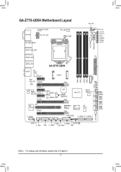
...ATX_12V_2X4 DP_HDMI_SPDIF ESATA_1394_USB USB30_LAN2 CPU_FAN HP_PWR LGA1155 PW_SW CMOS_SW RST_SW VCORE CPUVTT VSA CPUPLL DDRVTT VDIMM PCHIO SYS_FAN2 Debug LED (Note) ATX USB30_LAN1 AUDIO VIA VL810 PCIEX1_1 Intel® GbE LAN PCIEX16 GA-Z77X-UD5H mSATA PCIEX1_2 CODEC Atheros GbE LAN PCIEX1_3 PCIEX8 B_BIOS BBIOS_LED M_BIOS MBIOS_LED BAT Marvell 88SE9172 Intel® Z77 ... DDR3_1 F_USB30_1 ATX4P 76 GSATA3 10 SATA3 32 SATA2 54 SATA2 SYS_FAN1 SPDIF_O F_1394 F_USB1 F_PANEL GSATA3 8 TPM F_USB2 SYS_FAN4 SW4 (Note) For debug code information, please refer to Chapter 5. - 7 -
...ATX_12V_2X4 DP_HDMI_SPDIF ESATA_1394_USB USB30_LAN2 CPU_FAN HP_PWR LGA1155 PW_SW CMOS_SW RST_SW VCORE CPUVTT VSA CPUPLL DDRVTT VDIMM PCHIO SYS_FAN2 Debug LED (Note) ATX USB30_LAN1 AUDIO VIA VL810 PCIEX1_1 Intel® GbE LAN PCIEX16 GA-Z77X-UD5H mSATA PCIEX1_2 CODEC Atheros GbE LAN PCIEX1_3 PCIEX8 B_BIOS BBIOS_LED M_BIOS MBIOS_LED BAT Marvell 88SE9172 Intel® Z77 ... DDR3_1 F_USB30_1 ATX4P 76 GSATA3 10 SATA3 32 SATA2 54 SATA2 SYS_FAN1 SPDIF_O F_1394 F_USB1 F_PANEL GSATA3 8 TPM F_USB2 SYS_FAN4 SW4 (Note) For debug code information, please refer to Chapter 5. - 7 -

Manual
Page 31
...design may configure the way to turn off (S5). •• PW (Power Switch, Red): Connects to the hard drive activity LED on the chassis front panel. Hardware Installation Note the positive and negative pins before connecting the cables. One single short beep will be... speaker on the chassis front panel. You may differ by issuing a beep code. Hard Drive Reset Activity LED Switch Power LED Chassis Intrusion Header •• MSG/PWR (Message/Power/Sleep LED, Yellow/Purple): System Status LED Connects to the pin assignments below. 12) F_PANEL (Front Panel Header) Connect...
...design may configure the way to turn off (S5). •• PW (Power Switch, Red): Connects to the hard drive activity LED on the chassis front panel. Hardware Installation Note the positive and negative pins before connecting the cables. One single short beep will be... speaker on the chassis front panel. You may differ by issuing a beep code. Hard Drive Reset Activity LED Switch Power LED Chassis Intrusion Header •• MSG/PWR (Message/Power/Sleep LED, Yellow/Purple): System Status LED Connects to the pin assignments below. 12) F_PANEL (Front Panel Header) Connect...

Manual
Page 119
... started. Memory initialization. CPU PEI initialization. IOH SMM initialization. Reserved. NVRAM initialization. Reserved for OEM use . Reserved for AMI use (OEM DXE initialization codes). 5-4 Debug LED Codes Regular Boot Code 10 11 12~14 15 16~18 19 1A~2A 2B~2F 31 32~36 37~3A 3B~3E 3F~4F 60 61 62...
... started. Memory initialization. CPU PEI initialization. IOH SMM initialization. Reserved. NVRAM initialization. Reserved for OEM use . Reserved for AMI use (OEM DXE initialization codes). 5-4 Debug LED Codes Regular Boot Code 10 11 12~14 15 16~18 19 1A~2A 2B~2F 31 32~36 37~3A 3B~3E 3F~4F 60 61 62...


