
Manual
Page 1
...Technology utility to enable the Intel Smart Response Technology • The Intel Smart Response Technology requires a computer system with an Intel Z68 Chipset-based motherboard and an Intel Core series CPU. • The operating system must be installed to make it work as a cache of the hard disk...have installed the operating system before enabling the Smart Response Technology. 1. The actual BIOS Setup menu options you will see shall depend on the motherboard you have and the BIOS version. - 1 - It is 64 GB. The maximum cache memory size is recommended that you enable RAID ...
...Technology utility to enable the Intel Smart Response Technology • The Intel Smart Response Technology requires a computer system with an Intel Z68 Chipset-based motherboard and an Intel Core series CPU. • The operating system must be installed to make it work as a cache of the hard disk...have installed the operating system before enabling the Smart Response Technology. 1. The actual BIOS Setup menu options you will see shall depend on the motherboard you have and the BIOS version. - 1 - It is 64 GB. The maximum cache memory size is recommended that you enable RAID ...

Manual
Page 2
...above and restarting your system, find the IRST icon in the notification area and double-click it to install all motherboard drivers, including the Intel Rapid Storage Technology driver. Make sure the Intel Rapid Storage Technology driver version is complete, use the "...Xpress Install" function of the motherboard driver disk to open the Intel Rapid Storage Technology utility. - 2 - Launching the Intel Rapid Storage Technology utility to enable the Intel Smart...
...above and restarting your system, find the IRST icon in the notification area and double-click it to install all motherboard drivers, including the Intel Rapid Storage Technology driver. Make sure the Intel Rapid Storage Technology driver version is complete, use the "...Xpress Install" function of the motherboard driver disk to open the Intel Rapid Storage Technology utility. - 2 - Launching the Intel Rapid Storage Technology utility to enable the Intel Smart...
Manual
Page 2
Motherboard GA-Z68X-UD3R-B3 Apr. 29, 2011 Motherboard GA-Z68X-UD3R-B3 Apr. 29, 2011
Motherboard GA-Z68X-UD3R-B3 Apr. 29, 2011 Motherboard GA-Z68X-UD3R-B3 Apr. 29, 2011
Manual
Page 3
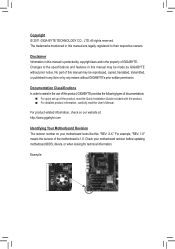
...without prior notice. For product-related information, check on our website at: http://www.gigabyte.com Identifying Your Motherboard Revision The revision number on your motherboard revision before updating motherboard BIOS, drivers, or when looking for technical information. Copyright © 2011 GIGA-...reproduced, copied, translated, transmitted, or published in the use of GIGABYTE. Documentation Classifications In order to their respective owners. Example: For example, "REV: 1.0" means the revision of the motherboard is the property of this manual may be made by copyright laws...
...without prior notice. For product-related information, check on our website at: http://www.gigabyte.com Identifying Your Motherboard Revision The revision number on your motherboard revision before updating motherboard BIOS, drivers, or when looking for technical information. Copyright © 2011 GIGA-...reproduced, copied, translated, transmitted, or published in the use of GIGABYTE. Documentation Classifications In order to their respective owners. Example: For example, "REV: 1.0" means the revision of the motherboard is the property of this manual may be made by copyright laws...
Manual
Page 4
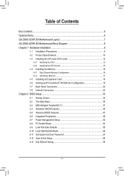
Table of Contents Box Contents...6 Optional Items...6 GA-Z68X-UD3R-B3 Motherboard Layout 7 GA-Z68X-UD3R-B3 Motherboard Block Diagram 8 Chapter 1 Hardware Installation 9 1-1 Installation Precautions 9 1-2 Product Specifications 10 1-3 Installing the CPU and CPU Cooler 13 1-3-1 Installing the CPU 13 1-3-2 Installing the CPU Cooler ...
Table of Contents Box Contents...6 Optional Items...6 GA-Z68X-UD3R-B3 Motherboard Layout 7 GA-Z68X-UD3R-B3 Motherboard Block Diagram 8 Chapter 1 Hardware Installation 9 1-1 Installation Precautions 9 1-2 Product Specifications 10 1-3 Installing the CPU and CPU Cooler 13 1-3-1 Installing the CPU 13 1-3-2 Installing the CPU Cooler ...
Manual
Page 6
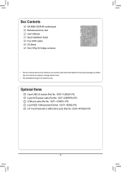
... port cable (Part No. 12CF1-1CM001-3*R) 2-port IEEE 1394a bracket (Part No. 12CF1-1IE008-0*R) 3.5" Front Panel with 2 USB 3.0/2.0 ports (Part No. 12CR1-FPX582-0*R) - 6 - Box Contents GA-Z68X-UD3R-B3 motherboard Motherboard driver disk User's Manual Quick Installation Guide Four SATA cables I/O Shield One 2-Way SLI bridge connector • The box contents above are subject to change...
... port cable (Part No. 12CF1-1CM001-3*R) 2-port IEEE 1394a bracket (Part No. 12CF1-1IE008-0*R) 3.5" Front Panel with 2 USB 3.0/2.0 ports (Part No. 12CR1-FPX582-0*R) - 6 - Box Contents GA-Z68X-UD3R-B3 motherboard Motherboard driver disk User's Manual Quick Installation Guide Four SATA cables I/O Shield One 2-Way SLI bridge connector • The box contents above are subject to change...
Manual
Page 7
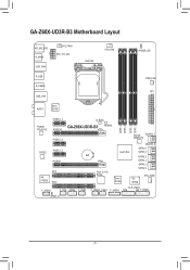
GA-Z68X-UD3R-B3 Motherboard Layout KB_MS_USB R_SPDIF USB_1394 SYS_FAN1 ATX_12V_2X4 LGA1155 CPU_FAN PHASE LED R_USB R_USB30 USB_LAN AUDIO Etron EJ168 PWR_FAN ATX PCIEX1_1 B_BIOS Realtek RTL8111E CODEC VIA VT6308 PCIEX16 PCIEX1_2 PCIEX1_3 PCIEX8 PCI1 PCI2 DDR3_4 DDR3_2 DDR3_3 DDR3_1 GA-Z68X-UD3R-B3 M_BIOS Marvell GSATA3_7 88SE9172 GSATA3_6 SATA3_1 Intel® Z68 SATA3_0 BAT SATA2_3 SATA2_2 SATA2_5 SATA2_4 PCIe to PCI Bridge Etron EJ168 iTE IT8728 SYS_FAN2 F_AUDIO CLR_CMOS F_1394 COMA F_USB3 F_USB2 F_USB1 F_USB30 TPM F_PANEL SPDIF_O - 7 -
GA-Z68X-UD3R-B3 Motherboard Layout KB_MS_USB R_SPDIF USB_1394 SYS_FAN1 ATX_12V_2X4 LGA1155 CPU_FAN PHASE LED R_USB R_USB30 USB_LAN AUDIO Etron EJ168 PWR_FAN ATX PCIEX1_1 B_BIOS Realtek RTL8111E CODEC VIA VT6308 PCIEX16 PCIEX1_2 PCIEX1_3 PCIEX8 PCI1 PCI2 DDR3_4 DDR3_2 DDR3_3 DDR3_1 GA-Z68X-UD3R-B3 M_BIOS Marvell GSATA3_7 88SE9172 GSATA3_6 SATA3_1 Intel® Z68 SATA3_0 BAT SATA2_3 SATA2_2 SATA2_5 SATA2_4 PCIe to PCI Bridge Etron EJ168 iTE IT8728 SYS_FAN2 F_AUDIO CLR_CMOS F_1394 COMA F_USB3 F_USB2 F_USB1 F_USB30 TPM F_PANEL SPDIF_O - 7 -
Manual
Page 8
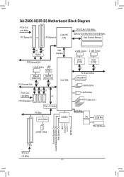
GA-Z68X-UD3R-B3 Motherboard Block Diagram PCIe CLK (100 MHz) 1 PCI Express x16 or 2 PCI Express x8 LGA1155 CPU CPU CLK+/- (100 MHz) DDR3 2133/1866/1600/1333/1066 ...
GA-Z68X-UD3R-B3 Motherboard Block Diagram PCIe CLK (100 MHz) 1 PCI Express x16 or 2 PCI Express x8 LGA1155 CPU CPU CLK+/- (100 MHz) DDR3 2133/1866/1600/1333/1066 ...
Manual
Page 9
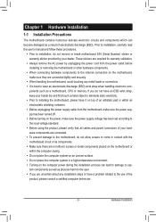
...manual and follow these procedures: •• Prior to installation, do not remove or break motherboard S/N (Serial Number) sticker or warranty sticker provided by unplugging the power cord from the motherboard, make sure the power supply has been turned off. •• Before turning on the... connectors. •• It is best to the use of your hardware components are connected. •• To prevent damage to the motherboard, do not have a problem related to wear an electrostatic discharge (ESD) wrist strap when handling electronic com- These stickers are required for ...
...manual and follow these procedures: •• Prior to installation, do not remove or break motherboard S/N (Serial Number) sticker or warranty sticker provided by unplugging the power cord from the motherboard, make sure the power supply has been turned off. •• Before turning on the... connectors. •• It is best to the use of your hardware components are connected. •• To prevent damage to the motherboard, do not have a problem related to wear an electrostatic discharge (ESD) wrist strap when handling electronic com- These stickers are required for ...
Manual
Page 12
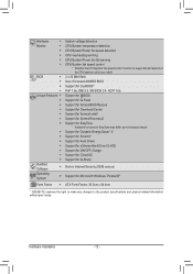
... ŠŠ Support for Xpress Install ŠŠ Support for Xpress Recovery2 ŠŠ Support for EasyTune * Available functions in EasyTune may differ by motherboard model. ŠŠ Support for Dynamic Energy Saver™ 2 ŠŠ Support for Smart 6™ ŠŠ Support for Auto Green Š... System ŠŠ Support for Microsoft® Windows 7/Vista/XP Form Factor ŠŠ ATX Form Factor; 30.5cm x 24.4cm * GIGABYTE reserves the right to make any changes to the product specifications and product-related information without prior notice.
... ŠŠ Support for Xpress Install ŠŠ Support for Xpress Recovery2 ŠŠ Support for EasyTune * Available functions in EasyTune may differ by motherboard model. ŠŠ Support for Dynamic Energy Saver™ 2 ŠŠ Support for Smart 6™ ŠŠ Support for Auto Green Š... System ŠŠ Support for Microsoft® Windows 7/Vista/XP Form Factor ŠŠ ATX Form Factor; 30.5cm x 24.4cm * GIGABYTE reserves the right to make any changes to the product specifications and product-related information without prior notice.
Manual
Page 13
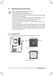
... Notch Triangle Pin One Marking on the CPU. Locate the alignment keys on the motherboard CPU socket and the notches on the CPU - 13 - Hardware Installation It is not recommended that the motherboard supports the CPU. (Go to GIGABYTE's website for the peripherals. LGA1155 CPU Socket Alignment Key Alignment Key Pin One Corner...
... Notch Triangle Pin One Marking on the CPU. Locate the alignment keys on the motherboard CPU socket and the notches on the CPU - 13 - Hardware Installation It is not recommended that the motherboard supports the CPU. (Go to GIGABYTE's website for the peripherals. LGA1155 CPU Socket Alignment Key Alignment Key Pin One Corner...
Manual
Page 14
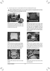
... correctly install the CPU into its locked position. Step 2: Remove the CPU socket cover as well. Step 5: Push the CPU socket lever back into the motherboard CPU socket. Hold your index finger down and away from the power outlet to prevent damage to the "REMOVE" mark) and then remove the cover...
... correctly install the CPU into its locked position. Step 2: Remove the CPU socket cover as well. Step 5: Push the CPU socket lever back into the motherboard CPU socket. Hold your index finger down and away from the power outlet to prevent damage to the "REMOVE" mark) and then remove the cover...
Manual
Page 15
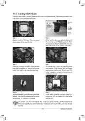
... the installed CPU. Step 2: Before installing the cooler, note the direction of the arrow sign on the motherboard. Step 4: You should hear a "click" when pushing down on the motherboard. If the push pin is inserted as the example cooler.) Direction of the Arrow Sign on the Male ...surface of arrow is to remove the cooler, on the contrary, is complete. Hardware Installation Step 6: Finally, attach the power connector of the motherboard. Inadequately removing the CPU cooler may adhere to the CPU fan header (CPU_FAN) on the push pins diagonally. Push down each push pin....
... the installed CPU. Step 2: Before installing the cooler, note the direction of the arrow sign on the motherboard. Step 4: You should hear a "click" when pushing down on the motherboard. If the push pin is inserted as the example cooler.) Direction of the Arrow Sign on the Male ...surface of arrow is to remove the cooler, on the contrary, is complete. Hardware Installation Step 6: Finally, attach the power connector of the motherboard. Inadequately removing the CPU cooler may adhere to the CPU fan header (CPU_FAN) on the push pins diagonally. Push down each push pin....
Manual
Page 16
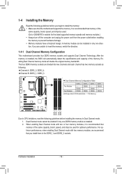
... memory bandwidth. The four DDR3 memory sockets are unable to insert the memory, switch the direction. 1-4-1 Dual Channel Memory Configuration This motherboard provides four DDR3 memory sockets and supports Dual Channel Technology. DS/SS DS/SS DDR3_1 DS/SS - DS/SS DDR3_3 - After ...memory to prevent hardware damage. •• Memory modules have a foolproof design. Dual Channel mode cannot be used . (Go to GIGABYTE's website for optimum performance. For optimum performance, when enabling Dual Channel mode with two or four memory modules, it is recommended that you...
... memory bandwidth. The four DDR3 memory sockets are unable to insert the memory, switch the direction. 1-4-1 Dual Channel Memory Configuration This motherboard provides four DDR3 memory sockets and supports Dual Channel Technology. DS/SS DS/SS DDR3_1 DS/SS - DS/SS DDR3_3 - After ...memory to prevent hardware damage. •• Memory modules have a foolproof design. Dual Channel mode cannot be used . (Go to GIGABYTE's website for optimum performance. For optimum performance, when enabling Dual Channel mode with two or four memory modules, it is recommended that you...
Manual
Page 17
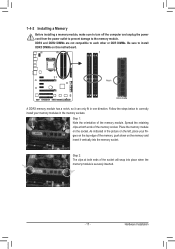
..., make sure to turn off the computer and unplug the power cord from the power outlet to prevent damage to install DDR3 DIMMs on this motherboard. Notch DDR3 DIMM A DDR3 memory module has a notch, so it vertically into place when the memory module is securely inserted. - 17...
..., make sure to turn off the computer and unplug the power cord from the power outlet to prevent damage to install DDR3 DIMMs on this motherboard. Notch DDR3 DIMM A DDR3 memory module has a notch, so it vertically into place when the memory module is securely inserted. - 17...
Manual
Page 18
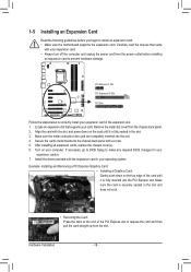
... and then pull the card straight up from the slot. If necessary, go to BIOS Setup to install an expansion card: • Make sure the motherboard supports the expansion card.
... and then pull the card straight up from the slot. If necessary, go to BIOS Setup to install an expansion card: • Make sure the motherboard supports the expansion card.
Manual
Page 19
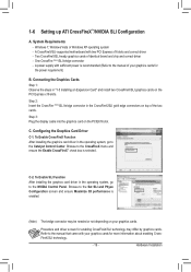
... enabling CrossFireX/SLI technology may be needed or not depending on the PCIEX16 slot. Windows 7, Windows Vista or Windows XP operating system - A CrossFireX/SLI-supported motherboard with sufficient power is recommended (Refer to the Set SLI and Physx Configuration screen and ensure Maximize 3D performance is selected. Step 2: Insert the CrossFire...
... enabling CrossFireX/SLI technology may be needed or not depending on the PCIEX16 slot. Windows 7, Windows Vista or Windows XP operating system - A CrossFireX/SLI-supported motherboard with sufficient power is recommended (Refer to the Set SLI and Physx Configuration screen and ensure Maximize 3D performance is selected. Step 2: Insert the CrossFire...
Manual
Page 20
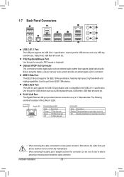
... Port The Gigabit Ethernet LAN port provides Internet connection at up to an external audio system that your device and then remove it from the motherboard. •• When removing the cable, pull it side to side to connect a PS/2 mouse or keyboard. Connection/ Speed LED Activity LED LAN Port Connection...
... Port The Gigabit Ethernet LAN port provides Internet connection at up to an external audio system that your device and then remove it from the motherboard. •• When removing the cable, pull it side to side to connect a PS/2 mouse or keyboard. Connection/ Speed LED Activity LED LAN Port Connection...
Manual
Page 22
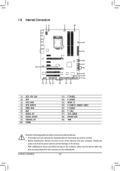
... 13) SPDIF_O 14) F_USB1/F_USB2/F_USB3 15) F_USB30 16) F_1394 17) CLR_CMOS 18) PHASE LED 19) TPM Read the following guidelines before turning on the motherboard.
... 13) SPDIF_O 14) F_USB1/F_USB2/F_USB3 15) F_USB30 16) F_1394 17) CLR_CMOS 18) PHASE LED 19) TPM Read the following guidelines before turning on the motherboard.
Manual
Page 23
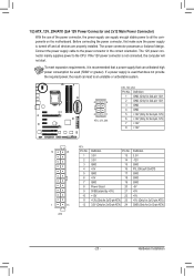
The power connector possesses a foolproof design. To meet expansion requirements, it is turned off and all the components on the motherboard. 1/2) ATX_12V_2X4/ATX (2x4 12V Power Connector and 2x12 Main Power Connector) With the use of the power connector, the power supply can supply enough stable ...
The power connector possesses a foolproof design. To meet expansion requirements, it is turned off and all the components on the motherboard. 1/2) ATX_12V_2X4/ATX (2x4 12V Power Connector and 2x12 Main Power Connector) With the use of the power connector, the power supply can supply enough stable ...


