
Manual
Page 1
... Technology utility to enable the Intel Smart Response Technology • The Intel Smart Response Technology requires a computer system with an Intel Z68 Chipset-based motherboard and an Intel Core series CPU. • The operating system must be installed to make it work as a cache of the hard disk. ... English Follow the steps below to enter BIOS Setup during the POST (Power-On Self-Test). Enabling RAID mode in BIOS Setup: Turn on the motherboard you also need an SSD to the SATA disk. • Supported operating systems include Windows 7 and Windows Vista. • If you have and ...
... Technology utility to enable the Intel Smart Response Technology • The Intel Smart Response Technology requires a computer system with an Intel Z68 Chipset-based motherboard and an Intel Core series CPU. • The operating system must be installed to make it work as a cache of the hard disk. ... English Follow the steps below to enter BIOS Setup during the POST (Power-On Self-Test). Enabling RAID mode in BIOS Setup: Turn on the motherboard you also need an SSD to the SATA disk. • Supported operating systems include Windows 7 and Windows Vista. • If you have and ...

Manual
Page 2
...-click it to install the operating system. Make sure the Intel Rapid Storage Technology driver version is complete, use the "Xpress Install" function of the motherboard driver disk to install all motherboard drivers, including the Intel Rapid Storage Technology driver. English 3.
...-click it to install the operating system. Make sure the Intel Rapid Storage Technology driver version is complete, use the "Xpress Install" function of the motherboard driver disk to install all motherboard drivers, including the Intel Rapid Storage Technology driver. English 3.
Manual
Page 2
Motherboard GA-Z68MX-UD2H-B3 Apr. 18, 2011 Motherboard GA-Z68MX-UD2H-B3 Apr. 18, 2011
Motherboard GA-Z68MX-UD2H-B3 Apr. 18, 2011 Motherboard GA-Z68MX-UD2H-B3 Apr. 18, 2011
Manual
Page 3
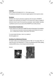
... this manual are legally registered to the specifications and features in this : "REV: X.X." Check your motherboard looks like this manual may be made by GIGABYTE without GIGABYTE's prior written permission. Example: The trademarks mentioned in the use of the product, read the Quick ... Changes to their respective owners. For product-related information, check on our website at: http://www.gigabyte.com Identifying Your Motherboard Revision The revision number on your motherboard revision before updating motherboard BIOS, drivers, or when looking for technical information.
... this manual are legally registered to the specifications and features in this : "REV: X.X." Check your motherboard looks like this manual may be made by GIGABYTE without GIGABYTE's prior written permission. Example: The trademarks mentioned in the use of the product, read the Quick ... Changes to their respective owners. For product-related information, check on our website at: http://www.gigabyte.com Identifying Your Motherboard Revision The revision number on your motherboard revision before updating motherboard BIOS, drivers, or when looking for technical information.
Manual
Page 4
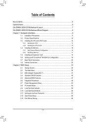
Table of Contents Box Contents...6 Optional Items...6 GA-Z68MX-UD2H-B3 Motherboard Layout 7 GA-Z68MX-UD2H-B3 Motherboard Block Diagram 8 Chapter 1 Hardware Installation 9 1-1 Installation Precautions 9 1-2 Product Specifications 10 1-3 Installing the CPU and CPU Cooler 13 1-3-1 Installing the CPU 13 1-3-2 Installing the CPU Cooler ...
Table of Contents Box Contents...6 Optional Items...6 GA-Z68MX-UD2H-B3 Motherboard Layout 7 GA-Z68MX-UD2H-B3 Motherboard Block Diagram 8 Chapter 1 Hardware Installation 9 1-1 Installation Precautions 9 1-2 Product Specifications 10 1-3 Installing the CPU and CPU Cooler 13 1-3-1 Installing the CPU 13 1-3-2 Installing the CPU Cooler ...
Manual
Page 6
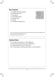
Box Contents GA-Z68MX-UD2H-B3 motherboard Motherboard driver disk User's Manual Quick Installation Guide Four SATA cables I/O Shield One 2-Way SLI bridge connector • The box contents above are subject to change without notice. • The motherboard image is for reference only and the actual items shall depend on the product package you obtain. The box contents...
Box Contents GA-Z68MX-UD2H-B3 motherboard Motherboard driver disk User's Manual Quick Installation Guide Four SATA cables I/O Shield One 2-Way SLI bridge connector • The box contents above are subject to change without notice. • The motherboard image is for reference only and the actual items shall depend on the product package you obtain. The box contents...
Manual
Page 7
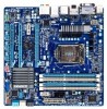
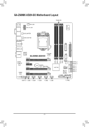
GA-Z68MX-UD2H-B3 Motherboard Layout KB_USB CPU_FAN ATX_12V_2X4 VGA_DVI LEVEL SHIFTER LEVEL SHIFTER DP_HDMI_SPDIF USB_ESATA LGA1155 PHASE LED iTE IT8728 TPM ATX USB30_LAN AUDIO Etron EJ168 GA-Z68MX-UD2H-B3 PCIEX16 SYS_FAN Realtek RTL8111E PCIEX1 PCIEX4 BAT M_BIOS B_BIOS CODEC PCIEX8 F_AUDIO COM DDR3_4 DDR3_2 DDR3_3 DDR3_1 Marvell 88SE9172 GSATA3_6 GSATA3_5 Intel® Z68 SATA2_4 Etron EJ168 SATA3_1 SATA3_0 SATA2_3 SATA2_2 F_USB30 CLR_CMOS SPDIF_O F_USB5 F_USB4 F_USB3 F_USB2 F_USB1 F_PANEL - 7 -
GA-Z68MX-UD2H-B3 Motherboard Layout KB_USB CPU_FAN ATX_12V_2X4 VGA_DVI LEVEL SHIFTER LEVEL SHIFTER DP_HDMI_SPDIF USB_ESATA LGA1155 PHASE LED iTE IT8728 TPM ATX USB30_LAN AUDIO Etron EJ168 GA-Z68MX-UD2H-B3 PCIEX16 SYS_FAN Realtek RTL8111E PCIEX1 PCIEX4 BAT M_BIOS B_BIOS CODEC PCIEX8 F_AUDIO COM DDR3_4 DDR3_2 DDR3_3 DDR3_1 Marvell 88SE9172 GSATA3_6 GSATA3_5 Intel® Z68 SATA2_4 Etron EJ168 SATA3_1 SATA3_0 SATA2_3 SATA2_2 F_USB30 CLR_CMOS SPDIF_O F_USB5 F_USB4 F_USB3 F_USB2 F_USB1 F_PANEL - 7 -
Manual
Page 8
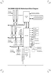
GA-Z68MX-UD2H-B3 Motherboard Block Diagram PCIe CLK (100 MHz) 1 PCI Express x16 or 2 PCI Express x8 LGA1155 CPU CPU CLK+/- (100 MHz) DDR3 2133/1866/1600/1333/1066 ...
GA-Z68MX-UD2H-B3 Motherboard Block Diagram PCIe CLK (100 MHz) 1 PCI Express x16 or 2 PCI Express x8 LGA1155 CPU CPU CLK+/- (100 MHz) DDR3 2133/1866/1600/1333/1066 ...

Manual
Page 9
... as a result of electrostatic discharge (ESD). Hardware Installation If you are connected tightly and securely. •• When handling the motherboard, avoid touching any installation steps or have a problem related to the use of the product, please consult a certified computer technician.... - 9 - Chapter 1 Hardware Installation 1-1 Installation Precautions The motherboard contains numerous delicate electronic circuits and components which can lead to damage to system components as well as physical harm to the...
... as a result of electrostatic discharge (ESD). Hardware Installation If you are connected tightly and securely. •• When handling the motherboard, avoid touching any installation steps or have a problem related to the use of the product, please consult a certified computer technician.... - 9 - Chapter 1 Hardware Installation 1-1 Installation Precautions The motherboard contains numerous delicate electronic circuits and components which can lead to damage to system components as well as physical harm to the...
Manual
Page 12
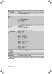
... Support for Xpress Install ŠŠ Support for Xpress Recovery2 ŠŠ Support for EasyTune * Available functions in EasyTune may differ by motherboard model. ŠŠ Support for Dynamic Energy Saver™ 2 ŠŠ Support for Smart 6™ ŠŠ Support for ...138;Š Support for Microsoft® Windows 7/Vista/XP Form Factor ŠŠ Micro ATX Form Factor; 244cm x 24.4cm * GIGABYTE reserves the right to make any changes to the product specifications and product-related information without prior notice. Back Panel Connectors ŠŠ ...
... Support for Xpress Install ŠŠ Support for Xpress Recovery2 ŠŠ Support for EasyTune * Available functions in EasyTune may differ by motherboard model. ŠŠ Support for Dynamic Energy Saver™ 2 ŠŠ Support for Smart 6™ ŠŠ Support for ...138;Š Support for Microsoft® Windows 7/Vista/XP Form Factor ŠŠ Micro ATX Form Factor; 244cm x 24.4cm * GIGABYTE reserves the right to make any changes to the product specifications and product-related information without prior notice. Back Panel Connectors ŠŠ ...

Manual
Page 13
... CPU cooler is not recommended that the motherboard supports the CPU. (Go to your hardware specifications including the CPU, graphics card, memory, hard drive, etc. 1-3-1 Installing the CPU A. Hardware Installation If you wish to set beyond the standard specifications, please do so according to GIGABYTE's website for the peripherals. 1-3 Installing the CPU...
... CPU cooler is not recommended that the motherboard supports the CPU. (Go to your hardware specifications including the CPU, graphics card, memory, hard drive, etc. 1-3-1 Installing the CPU A. Hardware Installation If you wish to set beyond the standard specifications, please do so according to GIGABYTE's website for the peripherals. 1-3 Installing the CPU...

Manual
Page 14
... the socket lever and use the other to correctly install the CPU into its locked position. Step 5: Push the CPU socket lever back into the motherboard CPU socket. Then completely lift the CPU socket lever and the metal load plate will be lifted as shown. NOTE: Hold the CPU socket lever...
... the socket lever and use the other to correctly install the CPU into its locked position. Step 5: Push the CPU socket lever back into the motherboard CPU socket. Then completely lift the CPU socket lever and the metal load plate will be lifted as shown. NOTE: Hold the CPU socket lever...
Manual
Page 15
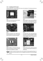
...Step 4: You should hear a "click" when pushing down on the push pins diagonally. Step 6: Finally, attach the power connector of the motherboard. Check that the Male and Female push pins are joined closely. (Refer to your CPU cooler installation manual for instructions on installing the cooler...Push down each push pin. Hardware Installation 1-3-2 Installing the CPU Cooler Follow the steps below to correctly install the CPU cooler on the motherboard. (The following procedure uses Intel® boxed cooler as the picture above shows, the installation is to install.) Step 3: Place the ...
...Step 4: You should hear a "click" when pushing down on the push pins diagonally. Step 6: Finally, attach the power connector of the motherboard. Check that the Male and Female push pins are joined closely. (Refer to your CPU cooler installation manual for instructions on installing the cooler...Push down each push pin. Hardware Installation 1-3-2 Installing the CPU Cooler Follow the steps below to correctly install the CPU cooler on the motherboard. (The following procedure uses Intel® boxed cooler as the picture above shows, the installation is to install.) Step 3: Place the ...

Manual
Page 16
... have a foolproof design. A memory module can be enabled if only one direction. DS/SS DDR3_1 - It is recommended that the motherboard supports the memory. Enabling Dual Channel memory mode will automatically detect the specifications and capacity of the memory. When enabling Dual Channel mode with... two memory modules, we recommend that memory of the same capacity, brand, speed, and chips be used . (Go to GIGABYTE's website for optimum performance. For optimum performance, when enabling Dual Channel mode with two or four memory modules, it is recommended that ...
... have a foolproof design. A memory module can be enabled if only one direction. DS/SS DDR3_1 - It is recommended that the motherboard supports the memory. Enabling Dual Channel memory mode will automatically detect the specifications and capacity of the memory. When enabling Dual Channel mode with... two memory modules, we recommend that memory of the same capacity, brand, speed, and chips be used . (Go to GIGABYTE's website for optimum performance. For optimum performance, when enabling Dual Channel mode with two or four memory modules, it is recommended that ...

Manual
Page 17
Follow the steps below to install DDR3 DIMMs on this motherboard. Step 1: Note the orientation of the memory, push down on the socket. Step 2: The clips at both ends of the memory socket. Hardware Installation Notch ...
Follow the steps below to install DDR3 DIMMs on this motherboard. Step 1: Note the orientation of the memory, push down on the socket. Step 2: The clips at both ends of the memory socket. Hardware Installation Notch ...
Manual
Page 18
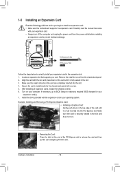
... the card and then pull the card straight up from the power outlet before you begin to install an expansion card: • Make sure the motherboard supports the expansion card. Carefully read the manual that supports your expansion card. • Always turn off the computer and unplug the power cord from...
... the card and then pull the card straight up from the power outlet before you begin to install an expansion card: • Make sure the motherboard supports the expansion card. Carefully read the manual that supports your expansion card. • Always turn off the computer and unplug the power cord from...

Manual
Page 19
... in the operating system, go to the manual of identical brand and chip and correct driver - One CrossFire (Note)/SLI bridge connector - A CrossFireX/SLI-supported motherboard with sufficient power is selected. Hardware Installation Step 2: Insert the CrossFire (Note)/SLI bridge connector in "1-5 Installing an Expansion Card" and install two CrossFireX/SLI...
... in the operating system, go to the manual of identical brand and chip and correct driver - One CrossFire (Note)/SLI bridge connector - A CrossFireX/SLI-supported motherboard with sufficient power is selected. Hardware Installation Step 2: Insert the CrossFire (Note)/SLI bridge connector in "1-5 Installing an Expansion Card" and install two CrossFireX/SLI...
Manual
Page 21
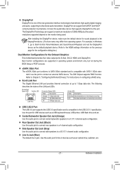
... optical drive, walkman, etc. - 21 - The Z68 Chipset supports RAID function. Rear Speaker Out Jack (Black) Use this audio jack for the Onboard Graphics: This motherboard provides four video output ports: D-Sub, DVI-D, HDMI, and DisplayPort. Side Speaker Out Jack (Gray) Use this port. Use the port to 1 Gbps data rate...
... optical drive, walkman, etc. - 21 - The Z68 Chipset supports RAID function. Rear Speaker Out Jack (Black) Use this audio jack for the Onboard Graphics: This motherboard provides four video output ports: D-Sub, DVI-D, HDMI, and DisplayPort. Side Speaker Out Jack (Gray) Use this port. Use the port to 1 Gbps data rate...

Manual
Page 22
... perform different functions via the audio software. Refer to prevent an electrical short inside the cable connector. Do not rock it straight out from the motherboard. • When removing the cable, pull it side to side to the instructions on setting up a 2/4/5.1/7.1-channel audio configuration in jack ( ). In addition to the...
... perform different functions via the audio software. Refer to prevent an electrical short inside the cable connector. Do not rock it straight out from the motherboard. • When removing the cable, pull it side to side to the instructions on setting up a 2/4/5.1/7.1-channel audio configuration in jack ( ). In addition to the...

Manual
Page 23
... and your devices are compliant with the connectors you wish to connect. •• Before installing the devices, be sure to the connector on the motherboard. - 23 - Hardware Installation 1-8 Internal Connectors 13 17 16 2 4 9 8 5 6 7 11 10 12 13 15 14 1) ATX_12V_2X4 2) ATX 3) CPU_FAN 4) SYS_FAN 5) BAT 6) SATA3_0/1 7) SATA2_2/3/4 8) GSATA3_5/6 9) COM 10) F_PANEL...
... and your devices are compliant with the connectors you wish to connect. •• Before installing the devices, be sure to the connector on the motherboard. - 23 - Hardware Installation 1-8 Internal Connectors 13 17 16 2 4 9 8 5 6 7 11 10 12 13 15 14 1) ATX_12V_2X4 2) ATX 3) CPU_FAN 4) SYS_FAN 5) BAT 6) SATA3_0/1 7) SATA2_2/3/4 8) GSATA3_5/6 9) COM 10) F_PANEL...


