
Manual
Page 1
GA-X58A-UD9 LGA1366 socket motherboard for Intel® Core™ i7 processor family User's Manual Rev. 1001 12ME-X58AUD9-1001R
GA-X58A-UD9 LGA1366 socket motherboard for Intel® Core™ i7 processor family User's Manual Rev. 1001 12ME-X58AUD9-1001R

Manual
Page 2
Motherboard GA-X58A-UD9 Apr. 12, 2010 Motherboard GA-X58A-UD9 Apr. 12, 2010
Motherboard GA-X58A-UD9 Apr. 12, 2010 Motherboard GA-X58A-UD9 Apr. 12, 2010

Manual
Page 3
...reproduced, copied, translated, transmitted, or published in the use GIGABYTE's unique features, read or download the information on/from the Support&Downloads\Motherboard\Technology Guide page on your motherboard revision before updating motherboard BIOS, drivers, or when looking for technical information. For...check on our website at: http://www.gigabyte.com.tw Identifying Your Motherboard Revision The revision number on our website. Example: Changes to use of this manual is 1.0. No part of GIGABYTE. Check your motherboard looks like this manual are legally registered...
...reproduced, copied, translated, transmitted, or published in the use GIGABYTE's unique features, read or download the information on/from the Support&Downloads\Motherboard\Technology Guide page on your motherboard revision before updating motherboard BIOS, drivers, or when looking for technical information. For...check on our website at: http://www.gigabyte.com.tw Identifying Your Motherboard Revision The revision number on our website. Example: Changes to use of this manual is 1.0. No part of GIGABYTE. Check your motherboard looks like this manual are legally registered...

Manual
Page 4
Table of Contents Box Contents...6 Optional Items...6 GA-X58A-UD9 Motherboard Layout 7 GA-X58A-UD9 Motherboard Block Diagram 8 Chapter 1 Hardware Installation 9 1-1 Installation Precautions 9 1-2 Product Specifications 10 1-3 Installing the CPU and CPU Cooler 13 1-3-1 Installing the CPU 13 1-3-2 Installing the CPU Cooler ...
Table of Contents Box Contents...6 Optional Items...6 GA-X58A-UD9 Motherboard Layout 7 GA-X58A-UD9 Motherboard Block Diagram 8 Chapter 1 Hardware Installation 9 1-1 Installation Precautions 9 1-2 Product Specifications 10 1-3 Installing the CPU and CPU Cooler 13 1-3-1 Installing the CPU 13 1-3-2 Installing the CPU Cooler ...

Manual
Page 6
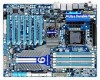
Box Contents GA-X58A-UD9 motherboard Motherboard driver disk User's Manual Quick Installation Guide One IDE cable Four SATA 3Gb/s cables One SATA bracket I/O Shield One Hybrid Silent-Pipe module kit One 2-... bridge connector One 4-Way SLI bridge connector Two 2-Way CrossFireX bridge connectors • The box contents above are subject to change without notice. • The motherboard image is for reference only and the actual items shall depend on the product package you obtain. Optional Items Floppy disk drive cable (Part No...
Box Contents GA-X58A-UD9 motherboard Motherboard driver disk User's Manual Quick Installation Guide One IDE cable Four SATA 3Gb/s cables One SATA bracket I/O Shield One Hybrid Silent-Pipe module kit One 2-... bridge connector One 4-Way SLI bridge connector Two 2-Way CrossFireX bridge connectors • The box contents above are subject to change without notice. • The motherboard image is for reference only and the actual items shall depend on the product package you obtain. Optional Items Floppy disk drive cable (Part No...

Manual
Page 7
GA-X58A-UD9 Motherboard Layout KB_MS R_SPDIF ATX_12V_2X CMOS_SW ATX_12V_2X_1 USB_1394_ESATA_2 USB_1394_ESATA_1 USB_LAN CPU_FAN CPU Voltage L1/2/3 CPU TEMP L1/2 LGA1366 FREQ. LED PW_SW ATX RST_SW PHASE LED DDR Voltage LED PWR_FAN GA-X58A-UD9 DDR3_2 USB30_LAN JMicron JMB362 AUDIO F_AUDIO SPDIF_I NEC D720200F1 ... LED Marvell 9128 IDE GSATA3_7 GSATA3_6 CODEC PCIEX8_1 PCIEX16_2 IT8720 SPDIF_O CD_IN PCIEX8_2 PCIEX16_3 PCIEX8_3 SYS_FAN1 PCIEX16_4 NF200 GIGABYTE SATA2 M_BIOS B_BIOS Intel® ICH10R TSB43AB23 SB Voltage L1/2/3 Debug BAT LED (Note) F_USB3 F_USB2 ...
GA-X58A-UD9 Motherboard Layout KB_MS R_SPDIF ATX_12V_2X CMOS_SW ATX_12V_2X_1 USB_1394_ESATA_2 USB_1394_ESATA_1 USB_LAN CPU_FAN CPU Voltage L1/2/3 CPU TEMP L1/2 LGA1366 FREQ. LED PW_SW ATX RST_SW PHASE LED DDR Voltage LED PWR_FAN GA-X58A-UD9 DDR3_2 USB30_LAN JMicron JMB362 AUDIO F_AUDIO SPDIF_I NEC D720200F1 ... LED Marvell 9128 IDE GSATA3_7 GSATA3_6 CODEC PCIEX8_1 PCIEX16_2 IT8720 SPDIF_O CD_IN PCIEX8_2 PCIEX16_3 PCIEX8_3 SYS_FAN1 PCIEX16_4 NF200 GIGABYTE SATA2 M_BIOS B_BIOS Intel® ICH10R TSB43AB23 SB Voltage L1/2/3 Debug BAT LED (Note) F_USB3 F_USB2 ...
Manual
Page 8
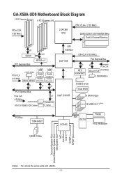
GA-X58A-UD9 Motherboard Block Diagram 3 PCI Express x8 4 PCI Express x16 CPU CLK+/- (133 MHz) PCIe CLK (100 MHz) LGA1366 CPU DDR3 2200/1333/1066/800 MHz Dual/3 ... RTL8111E LAN2 RJ45 Realtek RTL8111E x1 x1 x1 PCI Express Bus PCIe CLK (100 MHz) 2 SATA 3Gb/s ATA-133/100/66/33 IDE Channel x1 GIGABYTE SATA2 QPI Interface IOH CLK (133 MHz) Intel® X58 PCI Express Bus x1 NEC D720200F1 x1 PCIe CLK Marvell 9128 (100 MHz) 2 SATA 6Gb...
GA-X58A-UD9 Motherboard Block Diagram 3 PCI Express x8 4 PCI Express x16 CPU CLK+/- (133 MHz) PCIe CLK (100 MHz) LGA1366 CPU DDR3 2200/1333/1066/800 MHz Dual/3 ... RTL8111E LAN2 RJ45 Realtek RTL8111E x1 x1 x1 PCI Express Bus PCIe CLK (100 MHz) 2 SATA 3Gb/s ATA-133/100/66/33 IDE Channel x1 GIGABYTE SATA2 QPI Interface IOH CLK (133 MHz) Intel® X58 PCI Express Bus x1 NEC D720200F1 x1 PCIe CLK Marvell 9128 (100 MHz) 2 SATA 6Gb...
Manual
Page 9
...Before unplugging the power supply cable from the power outlet before installing or removing the motherboard or other hardware components. • When connecting hardware components to the internal connectors on the motherboard, make sure the power supply voltage has been set according to the local voltage...your hardware components are connected. • To prevent damage to the motherboard, do not remove or break motherboard S/N (Serial Number) sticker or warranty sticker provided by unplugging the power cord from the motherboard, make sure the power supply has been turned off. • ...
...Before unplugging the power supply cable from the power outlet before installing or removing the motherboard or other hardware components. • When connecting hardware components to the internal connectors on the motherboard, make sure the power supply voltage has been set according to the local voltage...your hardware components are connected. • To prevent damage to the motherboard, do not remove or break motherboard S/N (Serial Number) sticker or warranty sticker provided by unplugging the power cord from the motherboard, make sure the power supply has been turned off. • ...
Manual
Page 12
... PCI Express graphics cards, it is populated, its corresponding PCIEX16 slot will depend on the CPU cooler you install them in EasyTune may differ by motherboard model.
... PCI Express graphics cards, it is populated, its corresponding PCIEX16 slot will depend on the CPU cooler you install them in EasyTune may differ by motherboard model.
Manual
Page 13
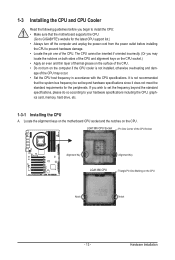
... bus frequency be inserted if oriented incorrectly. (Or you wish to set beyond the standard specifications, please do so according to GIGABYTE's website for the peripherals. Hardware Installation age of the CPU Socket Alignment Key Alignment Key LGA1366 CPU Triangle Pin One Marking on... the computer if the CPU cooler is not recommended that the motherboard supports the CPU. (Go to your hardware specifications including the CPU, graphics card, memory, hard drive, etc. 1-3-1 Installing the CPU ...
... bus frequency be inserted if oriented incorrectly. (Or you wish to set beyond the standard specifications, please do so according to GIGABYTE's website for the peripherals. Hardware Installation age of the CPU Socket Alignment Key Alignment Key LGA1366 CPU Triangle Pin One Marking on... the computer if the CPU cooler is not recommended that the motherboard supports the CPU. (Go to your hardware specifications including the CPU, graphics card, memory, hard drive, etc. 1-3-1 Installing the CPU ...
Manual
Page 14
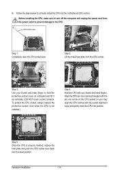
..., always replace the protective socket cover when the CPU is properly inserted, replace the load plate and push the CPU socket lever back into the motherboard CPU socket.
..., always replace the protective socket cover when the CPU is properly inserted, replace the load plate and push the CPU socket lever back into the motherboard CPU socket.
Manual
Page 15
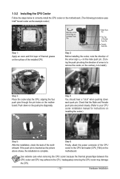
... the installation is to remove the cooler, on the contrary, is complete. Push down each push pin. Step 6: Finally, attach the power connector of the motherboard. Use extreme care when removing the CPU cooler because the thermal grease/tape between the CPU cooler and CPU may damage the CPU. - 15 - Step... surface of arrow is to install.) Step 3: Place the cooler atop the CPU, aligning the four push pins through the pin holes on the motherboard. Direction of the Arrow Sign on the Male Push Pin Male Push Pin The Top of Female Push Pin Female Push Pin Step 2: Before installing...
... the installation is to remove the cooler, on the contrary, is complete. Push down each push pin. Step 6: Finally, attach the power connector of the motherboard. Use extreme care when removing the CPU cooler because the thermal grease/tape between the CPU cooler and CPU may damage the CPU. - 15 - Step... surface of arrow is to install.) Step 3: Place the cooler atop the CPU, aligning the four push pins through the pin holes on the motherboard. Direction of the Arrow Sign on the Male Push Pin Male Push Pin The Top of Female Push Pin Female Push Pin Step 2: Before installing...
Manual
Page 16
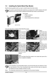
... the Hybrid Silent-Pipe module: If you want to connect the front audio module from the products illustrated. Screws included with the motherboard Hybrid Silent-Pipe Follow the steps below to install the Hybrid Silent-Pipe module: Step 1: Apply an even thin layer of thermal...the Hybrid Silent-Pipe Module Read the following guideline before installing the Hybrid Silent-Pipe module to avoid interference. Step 4: The picture on the motherboard, be sure to avoid shaking.) Step 2: Position the heatpipe underneath the heatsink of the Hybrid Silent-Pipe module into the tunnel of the ...
... the Hybrid Silent-Pipe module: If you want to connect the front audio module from the products illustrated. Screws included with the motherboard Hybrid Silent-Pipe Follow the steps below to install the Hybrid Silent-Pipe module: Step 1: Apply an even thin layer of thermal...the Hybrid Silent-Pipe Module Read the following guideline before installing the Hybrid Silent-Pipe module to avoid interference. Step 4: The picture on the motherboard, be sure to avoid shaking.) Step 2: Position the heatpipe underneath the heatsink of the Hybrid Silent-Pipe module into the tunnel of the ...
Manual
Page 17
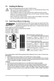
...- - Dual Channel-1. A memory module can be sure to insert the memory, switch the direction. 1-5-1 Dual/3 Channel Memory Configuration This motherboard provides six DDR3 memory sockets and supports Dual/3 Channel Technology. Dual or 3 Channel memory mode may double or triple the original memory bandwidth...begin to prevent hardware damage. • Memory modules have a foolproof design. Dual Channel mode cannot be used . (Go to GIGABYTE's website for the latest supported memory speeds and momery moudles.) • Always turn off the computer and unplug the power cord from...
...- - Dual Channel-1. A memory module can be sure to insert the memory, switch the direction. 1-5-1 Dual/3 Channel Memory Configuration This motherboard provides six DDR3 memory sockets and supports Dual/3 Channel Technology. Dual or 3 Channel memory mode may double or triple the original memory bandwidth...begin to prevent hardware damage. • Memory modules have a foolproof design. Dual Channel mode cannot be used . (Go to GIGABYTE's website for the latest supported memory speeds and momery moudles.) • Always turn off the computer and unplug the power cord from...
Manual
Page 18
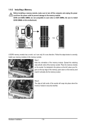
... below to correctly install your fingers on the top edge of the socket will snap into the memory socket. Place the memory module on this motherboard. As indicated in the picture on the left, place your memory modules in one direction. Hardware Installation - 18 - Notch DDR3 DIMM A DDR3 memory module has...
... below to correctly install your fingers on the top edge of the socket will snap into the memory socket. Place the memory module on this motherboard. As indicated in the picture on the left, place your memory modules in one direction. Hardware Installation - 18 - Notch DDR3 DIMM A DDR3 memory module has...

Manual
Page 19
... with the expansion card in the expansion slot. 1. PCI Express x16 Slot Follow the steps below to install an expansion card: • Make sure the motherboard supports the expansion card. Install the driver provided with a screw. 5.
... with the expansion card in the expansion slot. 1. PCI Express x16 Slot Follow the steps below to install an expansion card: • Make sure the motherboard supports the expansion card. Install the driver provided with a screw. 5.
Manual
Page 20
... technology include the Radeon HD 3800 series, Radeon HD 4800 and Radeon HD 5800 series. Note the direction of your graphics cards. A CrossFireX/SLI-supported motherboard with sufficient power is recommended (Note 2) (refer to ensure correct 4-Way SLI operation.) Step 3: Plug the display cable into the graphics card on the PCIEX16_1...
... technology include the Radeon HD 3800 series, Radeon HD 4800 and Radeon HD 5800 series. Note the direction of your graphics cards. A CrossFireX/SLI-supported motherboard with sufficient power is recommended (Note 2) (refer to ensure correct 4-Way SLI operation.) Step 3: Plug the display cable into the graphics card on the PCIEX16_1...
Manual
Page 22
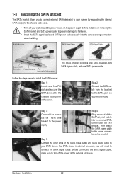
... switch on the bracket. Hardware Installation - 22 - Step 4: Plug one SATA power cable. Then attach the SATA power cable to the power connector on your motherboard. 1-8 Installing the SATA Bracket The SATA bracket allows you only need to connect the SATA signal cable. SATA Bracket SATA Signal Cable SATA Power Cable...
... switch on the bracket. Hardware Installation - 22 - Step 4: Plug one SATA power cable. Then attach the SATA power cable to the power connector on your motherboard. 1-8 Installing the SATA Bracket The SATA bracket allows you only need to connect the SATA signal cable. SATA Bracket SATA Signal Cable SATA Power Cable...
Manual
Page 23
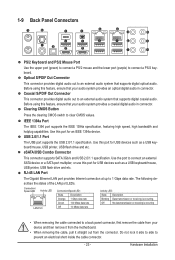
... rate. Optical S/PDIF Out Connector This connector provides digital audio out to an external audio system that your device and then remove it from the motherboard. • When removing the cable, pull it side to side to a back panel connector, first remove the cable from the connector. USB 2.0/1.1 Port The USB...
... rate. Optical S/PDIF Out Connector This connector provides digital audio out to an external audio system that your device and then remove it from the motherboard. • When removing the cable, pull it side to side to a back panel connector, first remove the cable from the connector. USB 2.0/1.1 Port The USB...
Manual
Page 25
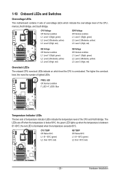
... LEDs indicate the temperature level of lighted LEDs. The LEDs are off when the temperature is overclocked. 1-10 Onboard LEDs and Switches Overvoltage LEDs This motherboard contains 4 sets of overvoltage LEDs which level the CPU is below 60oC;
... LEDs indicate the temperature level of lighted LEDs. The LEDs are off when the temperature is overclocked. 1-10 Onboard LEDs and Switches Overvoltage LEDs This motherboard contains 4 sets of overvoltage LEDs which level the CPU is below 60oC;


