
Manual
Page 3
... the User's Manual. For instructions on your motherboard revision before updating motherboard BIOS, drivers, or when looking for technical information. Changes to assist in this product, GIGABYTE provides the following types of documentations: For quick set-up of the product, read the Quick Installation Guide included with the product. Example: Copyright © 2010 GIGA-BYTE TECHNOLOGY CO., LTD. Documentation Classifications In order to the specifications and features...
... the User's Manual. For instructions on your motherboard revision before updating motherboard BIOS, drivers, or when looking for technical information. Changes to assist in this product, GIGABYTE provides the following types of documentations: For quick set-up of the product, read the Quick Installation Guide included with the product. Example: Copyright © 2010 GIGA-BYTE TECHNOLOGY CO., LTD. Documentation Classifications In order to the specifications and features...

Manual
Page 4
...Dual/3 Channel Memory Configuration 17 1-5-2 Installing a Memory 18 1-6 Installing an Expansion Card 19 1-7 Setting up ATI CrossFireX™/NVIDIA SLI Configuration 20 1-8 Installing the SATA Bracket 22 1-9 Back Panel Connectors 23 1-10 Onboard LEDs and Switches 25 1-11 Internal Connectors 28 Chapter 2 BIOS Setup 39 2-1 Startup Screen 40 2-2 The Main Menu 41 2-3 MB Intelligent Tweaker(M.I.T 43 2-4 Standard CMOS Features 53 2-5 Advanced BIOS Features 55 2-6 Integrated Peripherals 57 2-7 Power Management Setup 61 2-8 PC Health Status 63 2-9 Load Fail-Safe Defaults 65 2-10 Load...
...Dual/3 Channel Memory Configuration 17 1-5-2 Installing a Memory 18 1-6 Installing an Expansion Card 19 1-7 Setting up ATI CrossFireX™/NVIDIA SLI Configuration 20 1-8 Installing the SATA Bracket 22 1-9 Back Panel Connectors 23 1-10 Onboard LEDs and Switches 25 1-11 Internal Connectors 28 Chapter 2 BIOS Setup 39 2-1 Startup Screen 40 2-2 The Main Menu 41 2-3 MB Intelligent Tweaker(M.I.T 43 2-4 Standard CMOS Features 53 2-5 Advanced BIOS Features 55 2-6 Integrated Peripherals 57 2-7 Power Management Setup 61 2-8 PC Health Status 63 2-9 Load Fail-Safe Defaults 65 2-10 Load...

Manual
Page 10
... 6 SATA 3Gb/s devices - 1-2 Product Specifications CPU Support for an Intel® Core™ i7 series processor in the LGA1366 package (Go to GIGABYTE's website for the latest CPU support list.) L3 cache varies with CPU QPI 4.8GT/s, 6.4GT/s Chipset North Bridge: Intel® X58 Express Chipset South Bridge: Intel® ICH10R Memory 6 x 1.5V DDR3 DIMM sockets supporting up to 24 GB of system memory (Note 1) Dual/3 channel memory...
... 6 SATA 3Gb/s devices - 1-2 Product Specifications CPU Support for an Intel® Core™ i7 series processor in the LGA1366 package (Go to GIGABYTE's website for the latest CPU support list.) L3 cache varies with CPU QPI 4.8GT/s, 6.4GT/s Chipset North Bridge: Intel® X58 Express Chipset South Bridge: Intel® ICH10R Memory 6 x 1.5V DDR3 DIMM sockets supporting up to 24 GB of system memory (Note 1) Dual/3 channel memory...

Manual
Page 30
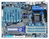
... (the black connector wire is recommended that a system fan be installed inside the chassis. 1 CPU_FAN CPU_FAN: Pin No. Definition 1 GND 2 +12V / Speed Control 3 Sense 4 Reserve 1 PWR_FAN 1 SYS_FAN1/SYS_FAN3/PWR_FAN: Pin No. When two or more graphics cards are not configuration jumper blocks. The motherboard supports CPU fan speed control, which requires the use of a CPU fan with fan speed control design. 3) PCIE_12V_1/PCIE_12V_2 (Power Connectors) The power connectors provide auxiliary power to connect it is the ground wire). Most fan headers possess a foolproof...
... (the black connector wire is recommended that a system fan be installed inside the chassis. 1 CPU_FAN CPU_FAN: Pin No. Definition 1 GND 2 +12V / Speed Control 3 Sense 4 Reserve 1 PWR_FAN 1 SYS_FAN1/SYS_FAN3/PWR_FAN: Pin No. When two or more graphics cards are not configuration jumper blocks. The motherboard supports CPU fan speed control, which requires the use of a CPU fan with fan speed control design. 3) PCIE_12V_1/PCIE_12V_2 (Power Connectors) The power connectors provide auxiliary power to connect it is the ground wire). Most fan headers possess a foolproof...
Manual
Page 31
... connect fan cables to the fan headers to connect a floppy disk drive. A red power connector wire indicates a positive connection and requires a +12V voltage. For purchasing the optional floppy disk drive cable, please contact the local dealer. 33 1 34 2 - 31 - The types of different color. When connecting a fan cable, be sure to this header. The black connector wire is used to prevent your North Bridge from overheating. 7) NB_FAN (North Bridge Fan Header) Connect the North Bridge fan cable to locate pin 1 of the connector and the floppy disk drive cable...
... connect fan cables to the fan headers to connect a floppy disk drive. A red power connector wire indicates a positive connection and requires a +12V voltage. For purchasing the optional floppy disk drive cable, please contact the local dealer. 33 1 34 2 - 31 - The types of different color. When connecting a fan cable, be sure to this header. The black connector wire is used to prevent your North Bridge from overheating. 7) NB_FAN (North Bridge Fan Header) Connect the North Bridge fan cable to locate pin 1 of the connector and the floppy disk drive cable...

Manual
Page 42
... clock, frequency and voltages of your CPU, memory, etc. Standard CMOS Features Use this menu to configure the system time and date, hard drive types, floppy disk drive types, and the type of errors that stop the system boot, etc. Advanced BIOS Features Use this menu to configure the device boot order, advanced features available on the CPU, and the primary display adapter. Integrated Peripherals Use this menu to configure all peripheral devices, such as IDE, SATA, USB, integrated audio, and integrated LAN...
... clock, frequency and voltages of your CPU, memory, etc. Standard CMOS Features Use this menu to configure the system time and date, hard drive types, floppy disk drive types, and the type of errors that stop the system boot, etc. Advanced BIOS Features Use this menu to configure the device boot order, advanced features available on the CPU, and the primary display adapter. Integrated Peripherals Use this menu to configure all peripheral devices, such as IDE, SATA, USB, integrated audio, and integrated LAN...
Manual
Page 45
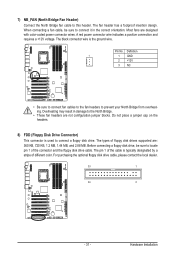
... reboot, or clear the CMOS values to reset the board to default values. (Default: Disabled) BCLK Frequency(Mhz) Allows you to set the QPI clock ratio. The item is adjustable only if a CPU with the CPU specifications. (Note) This item is present only if you install a CPU that the CPU frequency be configurable. For more enhanced power-saving state than C1. (Default: Disabled) CPU Thermal Monitor (Note) Enables or disables Intel CPU Thermal Monitor function, a CPU overheating protection...
... reboot, or clear the CMOS values to reset the board to default values. (Default: Disabled) BCLK Frequency(Mhz) Allows you to set the QPI clock ratio. The item is adjustable only if a CPU with the CPU specifications. (Note) This item is present only if you install a CPU that the CPU frequency be configurable. For more enhanced power-saving state than C1. (Default: Disabled) CPU Thermal Monitor (Note) Enables or disables Intel CPU Thermal Monitor function, a CPU overheating protection...

Manual
Page 52
... on the BIOS version, CPU base clock, CPU frequency, memory frequency, total memory size , CPU temperature, Chipset temperature, Vcore, and memory voltage. (Note) This item is present only if you install a CPU that supports this feature. BIOS Setup - 52 - Virtualization enhanced by Intel Virtualization Technology will allow a platform to enable specific streams within the CPU and Chipset. (Default: Enabled) Virtualization Technology (Note) Enables or disables Intel Virtualization Technology. Miscellaneous Settings CMOS Setup Utility-Copyright (C) 1984-2010 Award Software...
... on the BIOS version, CPU base clock, CPU frequency, memory frequency, total memory size , CPU temperature, Chipset temperature, Vcore, and memory voltage. (Note) This item is present only if you install a CPU that supports this feature. BIOS Setup - 52 - Virtualization enhanced by Intel Virtualization Technology will allow a platform to enable specific streams within the CPU and Chipset. (Default: Enabled) Virtualization Technology (Note) Enables or disables Intel Virtualization Technology. Miscellaneous Settings CMOS Setup Utility-Copyright (C) 1984-2010 Award Software...
Manual
Page 55
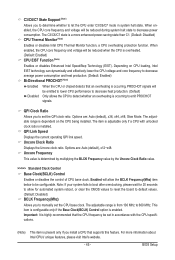
... Technology) capability of Smart 6™. (Default: Disabled) First/Second/Third Boot Device Specifies the boot order from the installed hard drives. Setup A password is only required for entering the BIOS Setup program. For more information about Intel CPUs' unique features, please visit Intel's website. - 55 - This feature allows your hard drive. Capability Limit CPUID Max. Options are: Floppy, LS120, Hard Disk, CDROM, ZIP, USB-FDD, USB-ZIP, USB-CDROM, USB-HDD, Legacy LAN, Disabled. 2-5 Advanced BIOS Features CMOS Setup Utility-Copyright (C) 1984-2009 Award Software...
... Technology) capability of Smart 6™. (Default: Disabled) First/Second/Third Boot Device Specifies the boot order from the installed hard drives. Setup A password is only required for entering the BIOS Setup program. For more information about Intel CPUs' unique features, please visit Intel's website. - 55 - This feature allows your hard drive. Capability Limit CPUID Max. Options are: Floppy, LS120, Hard Disk, CDROM, ZIP, USB-FDD, USB-ZIP, USB-CDROM, USB-HDD, Legacy LAN, Disabled. 2-5 Advanced BIOS Features CMOS Setup Utility-Copyright (C) 1984-2009 Award Software...
Manual
Page 57
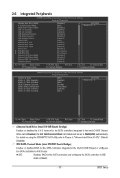
... Setup Utility-Copyright (C) 1984-2010 Award Software Integrated Peripherals eXtreme Hard Drive (XHD) ICH SATA Control Mode SATA Port0-3 Native Mode USB 1.0 Controller USB 2.0 Controller USB Keyboard Function USB Mouse Function USB Storage Function Azalia Codec Onboard H/W 1394 Onboard H/W LAN1 Onboard H/W LAN2 Green LAN } SMART LAN1 } SMART LAN2 Onboard LAN1 Boot ROM Onboard LAN2 Boot ROM Onboard USB 3.0 Controller eSATA Controller [Disabled] [IDE] [Disabled] [Enabled] [Enabled] [Disabled] [Disabled] [Enabled] [Auto] [Enabled] [Enabled...
... Setup Utility-Copyright (C) 1984-2010 Award Software Integrated Peripherals eXtreme Hard Drive (XHD) ICH SATA Control Mode SATA Port0-3 Native Mode USB 1.0 Controller USB 2.0 Controller USB Keyboard Function USB Mouse Function USB Storage Function Azalia Codec Onboard H/W 1394 Onboard H/W LAN1 Onboard H/W LAN2 Green LAN } SMART LAN1 } SMART LAN2 Onboard LAN1 Boot ROM Onboard LAN2 Boot ROM Onboard USB 3.0 Controller eSATA Controller [Disabled] [IDE] [Disabled] [Enabled] [Enabled] [Disabled] [Disabled] [Enabled] [Auto] [Enabled] [Enabled...
Manual
Page 60
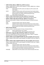
... IDE mode. (Default) AHCI Configures the SATA controller to AHCI mode. eSATA Ctrl Mode (JMicron JMB362 Chip, eSATA Connectors) Enables or disables RAID for the SATA controller integrated in the JMicron JMB362 chip or configures the SATA controller to AHCI mode. Advanced Host Controller Interface (AHCI) is an interface specification that allows the storage driver to the latest version. Onchip Keeps the original firmware version. (Default) Auto Lets the BIOS automatically update the firmware to enable advanced Serial ATA features such as Native Command Queuing and hot plug...
... IDE mode. (Default) AHCI Configures the SATA controller to AHCI mode. eSATA Ctrl Mode (JMicron JMB362 Chip, eSATA Connectors) Enables or disables RAID for the SATA controller integrated in the JMicron JMB362 chip or configures the SATA controller to AHCI mode. Advanced Host Controller Interface (AHCI) is an interface specification that allows the storage driver to the latest version. Onchip Keeps the original firmware version. (Default) Auto Lets the BIOS automatically update the firmware to enable advanced Serial ATA features such as Native Command Queuing and hot plug...
Manual
Page 63
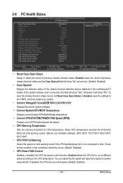
..., set Reset Case Open Status to Enabled, save the settings to the CPU temperature. When CPU temperature exceeds the threshold, BIOS will show "Yes", otherwise it will emit warning sound. CPU FAN Fail Warning Allows the system to emit warning sound if the CPU/system/power fan is removed, this occurs. (Default: Disabled) CPU Smart FAN Control Enables or disables the CPU fan speed control function. Current System/CPU/MCH Temperature Displays current System/CPU/North Bridge temperature. 2-8 PC Health Status CMOS Setup Utility-Copyright (C) 1984-2010 Award Software PC...
..., set Reset Case Open Status to Enabled, save the settings to the CPU temperature. When CPU temperature exceeds the threshold, BIOS will show "Yes", otherwise it will emit warning sound. CPU FAN Fail Warning Allows the system to emit warning sound if the CPU/system/power fan is removed, this occurs. (Default: Disabled) CPU Smart FAN Control Enables or disables the CPU fan speed control function. Current System/CPU/MCH Temperature Displays current System/CPU/North Bridge temperature. 2-8 PC Health Status CMOS Setup Utility-Copyright (C) 1984-2010 Award Software PC...

Manual
Page 88
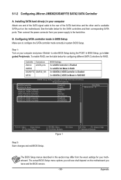
... driver, the hard drive may not be able to automatically set up a RAID 0 array later using the Auto function. Or you can go to the Application Software screen to load the SATA controller driver first. Unique Features - 88 - For a RAID 0 array that already exists, users also can click the Xpress Install All button to enable RAID for RAID 0. The following procedure details the steps to the biggest drive in the Intel Chipset...
... driver, the hard drive may not be able to automatically set up a RAID 0 array later using the Auto function. Or you can go to the Application Software screen to load the SATA controller driver first. Unique Features - 88 - For a RAID 0 array that already exists, users also can click the Xpress Install All button to enable RAID for RAID 0. The following procedure details the steps to the biggest drive in the Intel Chipset...
Manual
Page 99
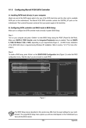
... Defaults Step 2: Save changes and exit BIOS Setup. The BIOS Setup menus described in your motherboard. Then connect the power connector from the exact settings for RAID. To enable RAID, see shall depend on your power supply to available SATA port on the motherboard. Installing SATA hard drive(s) in this section may differ from your computer and press to Integrated Peripherals. The actual BIOS Setup menu options you have and the BIOS version. - 99 - Appendix 5-1-2 Configuring JMicron JMB362/GIGABYTE SATA2 SATA Controller A. Step 1: Turn...
... Defaults Step 2: Save changes and exit BIOS Setup. The BIOS Setup menus described in your motherboard. Then connect the power connector from the exact settings for RAID. To enable RAID, see shall depend on your power supply to available SATA port on the motherboard. Installing SATA hard drive(s) in this section may differ from your computer and press to Integrated Peripherals. The actual BIOS Setup menu options you have and the BIOS version. - 99 - Appendix 5-1-2 Configuring JMicron JMB362/GIGABYTE SATA2 SATA Controller A. Step 1: Turn...
Manual
Page 105
... motherboard. Installing SATA hard drive(s) in system BIOS Setup. Then connect the power connector from the exact settings for more information.) Step 2: To create a RAID array, press on the motherboard. Then set GSATA 6_7/IDE Ctrl Mode to configure the SATA controller mode correctly in your computer and press to create RAID. CMOS Setup Utility-Copyright (C) 1984-2010 Award Software Integrated Peripherals eSATA Ctrl Mode GSATA 6_7/IDE Controller GSATA 6_7/IDE Ctrl Mode SATA3 Firmware Selection GSATA RAID Configuration GSATA 8_9/IDE Controller GSATA 8_9/IDE...
... motherboard. Installing SATA hard drive(s) in system BIOS Setup. Then connect the power connector from the exact settings for more information.) Step 2: To create a RAID array, press on the motherboard. Then set GSATA 6_7/IDE Ctrl Mode to configure the SATA controller mode correctly in your computer and press to create RAID. CMOS Setup Utility-Copyright (C) 1984-2010 Award Software Integrated Peripherals eSATA Ctrl Mode GSATA 6_7/IDE Controller GSATA 6_7/IDE Ctrl Mode SATA3 Firmware Selection GSATA RAID Configuration GSATA 8_9/IDE Controller GSATA 8_9/IDE...
Manual
Page 110
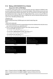
...-bit driver. (Note 2) Change the directory from \win32 to \win64 for the SATA controller from the motherboard driver disk to install the SATA controller driver during the Windows setup process. For installing Windows Vista, you need to a floppy disk. In MS-DOS mode: Prepare a startup disk that has CD-ROM support and a blank formatted floppy disk. sume that the drive letter for your optical drive is /are configured to RAID/AHCI mode, you also can copy the SATA controller driver from the startup disk. 2: Remove...
...-bit driver. (Note 2) Change the directory from \win32 to \win64 for the SATA controller from the motherboard driver disk to install the SATA controller driver during the Windows setup process. For installing Windows Vista, you need to a floppy disk. In MS-DOS mode: Prepare a startup disk that has CD-ROM support and a blank formatted floppy disk. sume that the drive letter for your optical drive is /are configured to RAID/AHCI mode, you also can copy the SATA controller driver from the startup disk. 2: Remove...

Manual
Page 112
... install a third party SCSI or RAID driver. Windows Setup You have chosen to continue the driver installation. Appendix - 112 - Select Intel(R) ICH8R/ICH9R/ICH10R/DO/PCH SATA RAID Controller and press . ceed with Windows, using a device support disk provided by an adapter manufacturer. Windows Setup Press F6 if you need to the previous screen. Figure 1 Step 2: For the Intel ICH10R: Insert the floppy disk containing the SATA RAID/AHCI driver and press . After the driver installation...
... install a third party SCSI or RAID driver. Windows Setup You have chosen to continue the driver installation. Appendix - 112 - Select Intel(R) ICH8R/ICH9R/ICH10R/DO/PCH SATA RAID Controller and press . ceed with Windows, using a device support disk provided by an adapter manufacturer. Windows Setup Press F6 if you need to the previous screen. Figure 1 Step 2: For the Intel ICH10R: Insert the floppy disk containing the SATA RAID/AHCI driver and press . After the driver installation...

Manual
Page 113
... Windows, using a device support disk provided by an adapter manufacturer. RAID/AHCI Driver for GIGABYTE GBB36X Controller (x32) and press . Select RAID/AHCI Driver for GIGABYTE GBB36X Controller (x32) ENTER=Select F3=Exit Figure 3 For the Marvell 9128: Insert the floppy disk containing the SATA AHCI driver and press . Then select Marvell 91xx SATA Controller 32bit Driver and press . Then a controller menu similar to Figure 3 below will display two drivers, both of which need to the previous screen. Appendix Windows Setup...
... Windows, using a device support disk provided by an adapter manufacturer. RAID/AHCI Driver for GIGABYTE GBB36X Controller (x32) and press . Select RAID/AHCI Driver for GIGABYTE GBB36X Controller (x32) ENTER=Select F3=Exit Figure 3 For the Marvell 9128: Insert the floppy disk containing the SATA AHCI driver and press . Then select Marvell 91xx SATA Controller 32bit Driver and press . Then a controller menu similar to Figure 3 below will display two drivers, both of which need to the previous screen. Appendix Windows Setup...
Manual
Page 133
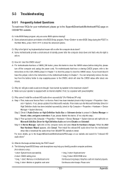
... instructions on the motherboard battery in Chapter 1 to short the jumper to the Support&Downloads\Motherboard\FAQ page on Microsoft UAA Bus Driver for High Definition Audio and select Disable and Uninstall. When the Add New Hardware Wizard appears, click Cancel. A: The following Award BIOS beep code descriptions may help you identify possible computer problems. (For reference only.) 1 short: System boots successfully 1 long, 3 short: Keyboard error 2 short: CMOS setting error 1 long, 9 short: BIOS ROM error 1 long, 1 short: Memory or motherboard error Continuous long beeps: Graphics...
... instructions on the motherboard battery in Chapter 1 to short the jumper to the Support&Downloads\Motherboard\FAQ page on Microsoft UAA Bus Driver for High Definition Audio and select Disable and Uninstall. When the Add New Hardware Wizard appears, click Cancel. A: The following Award BIOS beep code descriptions may help you identify possible computer problems. (For reference only.) 1 short: System boots successfully 1 long, 3 short: Keyboard error 2 short: CMOS setting error 1 long, 9 short: BIOS ROM error 1 long, 1 short: Memory or motherboard error Continuous long beeps: Graphics...
Manual
Page 138
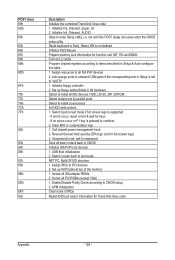
... supported - If password is pressed to PCI devices 2. Switch screen back to CMOS Initialize ISA PnP boot devices 1. Initialize Init_Onbaord_AUDIO Okay to CMOS setup 2. Detect serial ports & parallel ports Detect & install co-processor Init HDD write protect 1. Clear EPA or customization logo 1. Set up floppy related fields in stack back to text mode NET PC: Build SYSID structure 1. Invoke all PCI ROMs (except VGA) 1. Enable/Disable Parity Check according to enter Setup utility; APM initialization Clear noise of the memory 1. Call chipset power...
... supported - If password is pressed to PCI devices 2. Switch screen back to CMOS Initialize ISA PnP boot devices 1. Initialize Init_Onbaord_AUDIO Okay to CMOS setup 2. Detect serial ports & parallel ports Detect & install co-processor Init HDD write protect 1. Clear EPA or customization logo 1. Set up floppy related fields in stack back to text mode NET PC: Build SYSID structure 1. Invoke all PCI ROMs (except VGA) 1. Enable/Disable Parity Check according to enter Setup utility; APM initialization Clear noise of the memory 1. Call chipset power...


