
Manual
Page 1
... the Intel Chipset. (Note 2) It is added. A. Without the driver, the hard drive may not be able to set up all motherboard drivers, including the X.H.D utility. B. Step 2: Install the RAID driver and operating system The X.H.D utility supports Windows 7/Vista/XP. Or ... RAID 0, RAID 1, or other supported RAID array depending on your data to load the SATA controller driver first. eXtreme Hard Drive (X.H.D) With GIGABYTE eXtreme Hard Drive (X.H.D)(Note 1), users can quickly configure a RAIDready system for complex and time-consuming configurations. For a RAID 0 array that 's...
... the Intel Chipset. (Note 2) It is added. A. Without the driver, the hard drive may not be able to set up all motherboard drivers, including the X.H.D utility. B. Step 2: Install the RAID driver and operating system The X.H.D utility supports Windows 7/Vista/XP. Or ... RAID 0, RAID 1, or other supported RAID array depending on your data to load the SATA controller driver first. eXtreme Hard Drive (X.H.D) With GIGABYTE eXtreme Hard Drive (X.H.D)(Note 1), users can quickly configure a RAIDready system for complex and time-consuming configurations. For a RAID 0 array that 's...
Manual
Page 1
GA-X58A-UD5 LGA1366 socket motherboard for Intel® Core™ i7 processor family User's Manual Rev. 1001 12ME-X58AUD5-1001R
GA-X58A-UD5 LGA1366 socket motherboard for Intel® Core™ i7 processor family User's Manual Rev. 1001 12ME-X58AUD5-1001R
Manual
Page 2
Motherboard GA-X58A-UD5 Dec. 25, 2009 Motherboard GA-X58A-UD5 Dec. 25, 2009
Motherboard GA-X58A-UD5 Dec. 25, 2009 Motherboard GA-X58A-UD5 Dec. 25, 2009
Manual
Page 3
... included with the product. For product-related information, check on our website at: http://www.gigabyte.com.tw Identifying Your Motherboard Revision The revision number on how to the specifications and features in the use GIGABYTE's unique features, read the User's Manual. For example, "REV: 1.0" means the revision ..., copied, translated, transmitted, or published in this manual may be made by copyright laws and is the property of the motherboard is protected by GIGABYTE without GIGABYTE's prior written permission. Example: Copyright © 2009 GIGA-BYTE TECHNOLOGY CO., LTD.
... included with the product. For product-related information, check on our website at: http://www.gigabyte.com.tw Identifying Your Motherboard Revision The revision number on how to the specifications and features in the use GIGABYTE's unique features, read the User's Manual. For example, "REV: 1.0" means the revision ..., copied, translated, transmitted, or published in this manual may be made by copyright laws and is the property of the motherboard is protected by GIGABYTE without GIGABYTE's prior written permission. Example: Copyright © 2009 GIGA-BYTE TECHNOLOGY CO., LTD.
Manual
Page 4
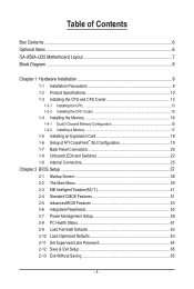
Table of Contents Box Contents...6 Optional Items...6 GA-X58A-UD5 Motherboard Layout 7 Block Diagram...8 Chapter 1 Hardware Installation 9 1-1 Installation Precautions 9 1-2 Product Specifications 10 1-3 Installing the CPU and CPU Cooler 13 1-3-1 Installing the CPU 13 1-3-2 Installing the CPU ...
Table of Contents Box Contents...6 Optional Items...6 GA-X58A-UD5 Motherboard Layout 7 Block Diagram...8 Chapter 1 Hardware Installation 9 1-1 Installation Precautions 9 1-2 Product Specifications 10 1-3 Installing the CPU and CPU Cooler 13 1-3-1 Installing the CPU 13 1-3-2 Installing the CPU ...
Manual
Page 6
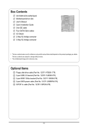
.... 12CF1-1IE008-0*R) 2-port SATA power cable (Part No. 12CF1-2SERPW-0*R) S/PDIF In cable (Part No. 12CR1-1SPDIN-0*R) - 6 - Box Contents GA-X58A-UD5 motherboard Motherboard driver disk User's Manual Quick Installation Guide One IDE cable Four SATA 3Gb/s cables I/O Shield 2-Way SLI bridge connector 3-Way SLI bridge connector •...; The box contents above are subject to change without notice. • The motherboard image is for reference only and the actual items shall depend on the product package you obtain. The box contents are for reference...
.... 12CF1-1IE008-0*R) 2-port SATA power cable (Part No. 12CF1-2SERPW-0*R) S/PDIF In cable (Part No. 12CR1-1SPDIN-0*R) - 6 - Box Contents GA-X58A-UD5 motherboard Motherboard driver disk User's Manual Quick Installation Guide One IDE cable Four SATA 3Gb/s cables I/O Shield 2-Way SLI bridge connector 3-Way SLI bridge connector •...; The box contents above are subject to change without notice. • The motherboard image is for reference only and the actual items shall depend on the product package you obtain. The box contents are for reference...
Manual
Page 7
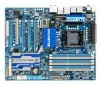
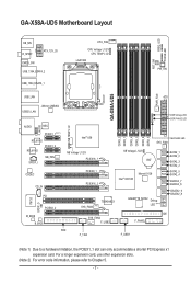
... CMOS_SW USB_1394_ESATA_2 USB_1394_ESATA_1 CPU_FAN CPU Voltage L1/2/3 CPU TEMP L1/2 LGA1366 RST_SW PW_SW GA-X58A-UD5 PWR_FAN USB_LAN ATX USB30_LAN JMicron JMB362 DDR Voltage LED DDR PHASE LED F_AUDIO NB ...GIGABYTE SATA2 Debug LED (Note 2) GSATA2_9 GSATA2_8 SYS_FAN2 F_USB2 IDE F_PANEL FDD F_1394 F_USB1 (Note 1) Due to Chapter 5. - 7 - For a longer expansion card, use other expansion slots. (Note 2) For error code information, please refer to a hardware limitation, the PCIEX1_1 slot can only accommodate a shorter PCI Express x1 expansion card. GA-X58A-UD5 Motherboard...
... CMOS_SW USB_1394_ESATA_2 USB_1394_ESATA_1 CPU_FAN CPU Voltage L1/2/3 CPU TEMP L1/2 LGA1366 RST_SW PW_SW GA-X58A-UD5 PWR_FAN USB_LAN ATX USB30_LAN JMicron JMB362 DDR Voltage LED DDR PHASE LED F_AUDIO NB ...GIGABYTE SATA2 Debug LED (Note 2) GSATA2_9 GSATA2_8 SYS_FAN2 F_USB2 IDE F_PANEL FDD F_1394 F_USB1 (Note 1) Due to Chapter 5. - 7 - For a longer expansion card, use other expansion slots. (Note 2) For error code information, please refer to a hardware limitation, the PCIEX1_1 slot can only accommodate a shorter PCI Express x1 expansion card. GA-X58A-UD5 Motherboard...
Manual
Page 9
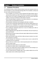
...have an ESD wrist strap, keep your hands dry and first touch a metal object to eliminate static electricity. • Prior to installing the motherboard, please have a problem related to the use of your dealer. Hardware Installation Prior to installation, carefully read the user's manual and follow these...for warranty validation. • Always remove the AC power by your hardware components are connected tightly and securely. • When handling the motherboard, avoid touching any installation steps or have it on top of an antistatic pad or within the computer casing. • Do not ...
...have an ESD wrist strap, keep your hands dry and first touch a metal object to eliminate static electricity. • Prior to installing the motherboard, please have a problem related to the use of your dealer. Hardware Installation Prior to installation, carefully read the user's manual and follow these...for warranty validation. • Always remove the AC power by your hardware components are connected tightly and securely. • When handling the motherboard, avoid touching any installation steps or have it on top of an antistatic pad or within the computer casing. • Do not ...
Manual
Page 12
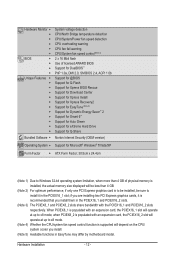
... Express graphics card is to be installed, be sure to install it is recommended that you install. (Note 5) Available functions in EasyTune may differ by motherboard model. Hardware Monitor w w w w w w BIOS w w w w Unique Features w w w w w w w w w w w w Bundled Software w System voltage detection CPU/North Bridge temperature detection CPU/System/Power fan speed detection CPU overheating warning...
... Express graphics card is to be installed, be sure to install it is recommended that you install. (Note 5) Available functions in EasyTune may differ by motherboard model. Hardware Monitor w w w w w w BIOS w w w w Unique Features w w w w w w w w w w w w Bundled Software w System voltage detection CPU/North Bridge temperature detection CPU/System/Power fan speed detection CPU overheating warning...
Manual
Page 13
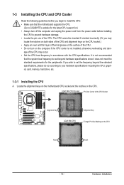
... for the latest CPU support list.) • Always turn on the computer if the CPU cooler is not recommended that the motherboard supports the CPU. (Go to GIGABYTE's website for the peripherals. If you begin to install the CPU: • Make sure that the system bus frequency be ...of the CPU Socket Alignment Key Alignment Key LGA1366 CPU Triangle Pin One Marking on the CPU. Hardware Installation Locate the alignment keys on the motherboard CPU socket and the notches on the CPU Notch Notch - 13 - 1-3 Installing the CPU and CPU Cooler Read the following guidelines before...
... for the latest CPU support list.) • Always turn on the computer if the CPU cooler is not recommended that the motherboard supports the CPU. (Go to GIGABYTE's website for the peripherals. If you begin to install the CPU: • Make sure that the system bus frequency be ...of the CPU Socket Alignment Key Alignment Key LGA1366 CPU Triangle Pin One Marking on the CPU. Hardware Installation Locate the alignment keys on the motherboard CPU socket and the notches on the CPU Notch Notch - 13 - 1-3 Installing the CPU and CPU Cooler Read the following guidelines before...
Manual
Page 14
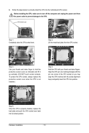
... socket contacts. Step 5: Once the CPU is not installed.) Step 4: Hold the CPU with the socket alignment keys) and gently insert the CPU into the motherboard CPU socket. B. CPU Socket Lever Step 1: Completely raise the CPU socket lever.
... socket contacts. Step 5: Once the CPU is not installed.) Step 4: Hold the CPU with the socket alignment keys) and gently insert the CPU into the motherboard CPU socket. B. CPU Socket Lever Step 1: Completely raise the CPU socket lever.

Manual
Page 15
...push pins diagonally. Check that the Male and Female push pins are joined closely. (Refer to correctly install the CPU cooler on the motherboard. (The following procedure uses Intel® boxed cooler as the picture above shows, the installation is complete. 1-3-2 Installing the CPU ...below to your CPU cooler installation manual for instructions on installing the cooler.) Step 5: After the installation, check the back of the motherboard. Step 6: Finally, attach the power connector of the installed CPU. Use extreme care when removing the CPU cooler because the thermal grease...
...push pins diagonally. Check that the Male and Female push pins are joined closely. (Refer to correctly install the CPU cooler on the motherboard. (The following procedure uses Intel® boxed cooler as the picture above shows, the installation is complete. 1-3-2 Installing the CPU ...below to your CPU cooler installation manual for instructions on installing the cooler.) Step 5: After the installation, check the back of the motherboard. Step 6: Finally, attach the power connector of the installed CPU. Use extreme care when removing the CPU cooler because the thermal grease...
Manual
Page 16
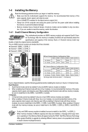
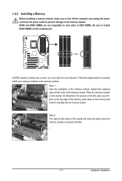
...Memory Mode will automatically detect the specifications and capacity of the same capacity, brand, speed, and chips be used. (Go to GIGABYTE's website for the latest memory support list.) • Always turn off the computer and unplug the power cord from the power outlet... the same capacity, brand, speed, and chips be sure to insert the memory, switch the direction. 1-4-1 Dual/3 Channel Memory Configuration This motherboard provides six DDR3 memory sockets and supports Dual/3 Channel Technology. The six DDR3 memory sockets are installed, a message which says mem- When enabling...
...Memory Mode will automatically detect the specifications and capacity of the same capacity, brand, speed, and chips be used. (Go to GIGABYTE's website for the latest memory support list.) • Always turn off the computer and unplug the power cord from the power outlet... the same capacity, brand, speed, and chips be sure to insert the memory, switch the direction. 1-4-1 Dual/3 Channel Memory Configuration This motherboard provides six DDR3 memory sockets and supports Dual/3 Channel Technology. The six DDR3 memory sockets are installed, a message which says mem- When enabling...
Manual
Page 17
..., make sure to turn off the computer and unplug the power cord from the power outlet to prevent damage to install DDR3 DIMMs on this motherboard. Follow the steps below to correctly install your fingers on the left, place your memory modules in one direction. As indicated in the picture on...
..., make sure to turn off the computer and unplug the power cord from the power outlet to prevent damage to install DDR3 DIMMs on this motherboard. Follow the steps below to correctly install your fingers on the left, place your memory modules in one direction. As indicated in the picture on...
Manual
Page 18
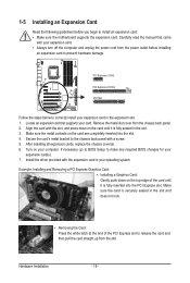
... that came with a screw. 5. Remove the metal slot cover from the power outlet before you begin to install an expansion card: • Make sure the motherboard supports the expansion card. Make sure the metal contacts on your expansion card(s). 7. 1-5 Installing an Expansion Card Read the following guidelines before installing an expansion...
... that came with a screw. 5. Remove the metal slot cover from the power outlet before you begin to install an expansion card: • Make sure the motherboard supports the expansion card. Make sure the metal contacts on your expansion card(s). 7. 1-5 Installing an Expansion Card Read the following guidelines before installing an expansion...
Manual
Page 19
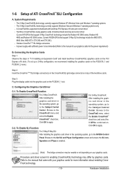
... slots.) Step 2: Insert the CrossFire (Note)/SLI bridge connector(s) in the operating system, go to apply. Browse to the Catalyst Control Center. A CrossFireX/SLI-supported motherboard with sufficient power is enabled. (Note) The bridge connectors may differ by graphics cards. Two/three CrossFireX/SLI-ready graphics cards of ATI CrossFireX™...
... slots.) Step 2: Insert the CrossFire (Note)/SLI bridge connector(s) in the operating system, go to apply. Browse to the Catalyst Control Center. A CrossFireX/SLI-supported motherboard with sufficient power is enabled. (Note) The bridge connectors may differ by graphics cards. Two/three CrossFireX/SLI-ready graphics cards of ATI CrossFireX™...

Manual
Page 20
... audio out to an external audio system that your audio system provides a coaxial digital audio in connector. Do not rock it straight out from the motherboard. • When removing the cable, pull it side to side to a back panel connector, first remove the cable from your audio system provides an optical...
... audio out to an external audio system that your audio system provides a coaxial digital audio in connector. Do not rock it straight out from the motherboard. • When removing the cable, pull it side to side to a back panel connector, first remove the cable from your audio system provides an optical...
Manual
Page 22
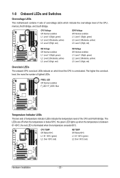
... the number of the CPU and North Bridge. the red LED is illuminated when the temperature exceeds 80oC. 1-8 Onboard LEDs and Switches Overvoltage LEDs This motherboard contains 4 sets of overvoltage LEDs which level the CPU is overclocked.
... the number of the CPU and North Bridge. the red LED is illuminated when the temperature exceeds 80oC. 1-8 Onboard LEDs and Switches Overvoltage LEDs This motherboard contains 4 sets of overvoltage LEDs which level the CPU is overclocked.

Manual
Page 23
... loading, the more the number of lighted LEDs. - 23 - To enable the Phase LED display function, please first enable Dynamic Energy Saver 2. Quick Switches This motherboard has 2 quick buttons: power button and reset button. The power button and reset button allow users to quickly turn on/off or reset the computer...
... loading, the more the number of lighted LEDs. - 23 - To enable the Phase LED display function, please first enable Dynamic Energy Saver 2. Quick Switches This motherboard has 2 quick buttons: power button and reset button. The power button and reset button allow users to quickly turn on/off or reset the computer...

Manual
Page 25
..., make sure your devices are compliant with the connectors you wish to connect. • Before installing the devices, be sure to the connector on the motherboard. - 25 - Unplug the power cord from the power outlet to prevent damage to the devices. • After installing the device and before connecting external devices...
..., make sure your devices are compliant with the connectors you wish to connect. • Before installing the devices, be sure to the connector on the motherboard. - 25 - Unplug the power cord from the power outlet to prevent damage to the devices. • After installing the device and before connecting external devices...


