
Manual
Page 1
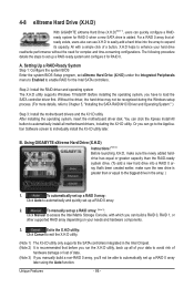
... equal or greater capacity than the RAID-ready system drive. (To add a new hard drive into the array to load the SATA controller driver first. Setting Up a RAID-Ready System Step 1: Configure the system BIOS Enter the system BIOS Setup program, set up a RAID 0 array. 2. Step 2: Install the RAID driver and operating system The X.H.D utility supports Windows 7/Vista/XP. eXtreme Hard Drive (X.H.D) With GIGABYTE eXtreme Hard Drive (X.H.D)(Note 1), users can quickly configure a RAIDready system for RAID 0. All with which you have...
... equal or greater capacity than the RAID-ready system drive. (To add a new hard drive into the array to load the SATA controller driver first. Setting Up a RAID-Ready System Step 1: Configure the system BIOS Enter the system BIOS Setup program, set up a RAID 0 array. 2. Step 2: Install the RAID driver and operating system The X.H.D utility supports Windows 7/Vista/XP. eXtreme Hard Drive (X.H.D) With GIGABYTE eXtreme Hard Drive (X.H.D)(Note 1), users can quickly configure a RAIDready system for RAID 0. All with which you have...
Manual
Page 3
..., carefully read or download the information on/from the Support&Downloads\Motherboard\Technology Guide page on our website. For product-related information, check on our website at: http://www.gigabyte.com.tw Identifying Your Motherboard Revision The revision number on how to the specifications and features in the use GIGABYTE's unique features, read the User's Manual. For instructions on your motherboard revision before updating motherboard BIOS, drivers, or when...
..., carefully read or download the information on/from the Support&Downloads\Motherboard\Technology Guide page on our website. For product-related information, check on our website at: http://www.gigabyte.com.tw Identifying Your Motherboard Revision The revision number on how to the specifications and features in the use GIGABYTE's unique features, read the User's Manual. For instructions on your motherboard revision before updating motherboard BIOS, drivers, or when...
Manual
Page 4
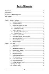
......6 GA-X58A-UD5 Motherboard Layout 7 Block Diagram...8 Chapter 1 Hardware Installation 9 1-1 Installation Precautions 9 1-2 Product Specifications 10 1-3 Installing the CPU and CPU Cooler 13 1-3-1 Installing the CPU 13 1-3-2 Installing the CPU Cooler 15 1-4 Installing the Memory 16 1-4-1 Dual/3 Channel Memory Configuration 16 1-4-2 Installing a Memory 17 1-5 Installing an Expansion Card 18 1-6 Setup of ATI CrossFireX™/SLI Configuration 19 1-7 Back Panel Connectors 20 1-8 Onboard LEDs and Switches 22 1-9 Internal Connectors 25 Chapter 2 BIOS Setup 37 2-1 Startup Screen...
......6 GA-X58A-UD5 Motherboard Layout 7 Block Diagram...8 Chapter 1 Hardware Installation 9 1-1 Installation Precautions 9 1-2 Product Specifications 10 1-3 Installing the CPU and CPU Cooler 13 1-3-1 Installing the CPU 13 1-3-2 Installing the CPU Cooler 15 1-4 Installing the Memory 16 1-4-1 Dual/3 Channel Memory Configuration 16 1-4-2 Installing a Memory 17 1-5 Installing an Expansion Card 18 1-6 Setup of ATI CrossFireX™/SLI Configuration 19 1-7 Back Panel Connectors 20 1-8 Onboard LEDs and Switches 22 1-9 Internal Connectors 25 Chapter 2 BIOS Setup 37 2-1 Startup Screen...
Manual
Page 10
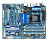
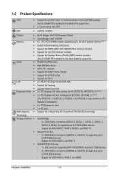
... 6 SATA 3Gb/s devices - 1-2 Product Specifications CPU Support for an Intel® Core™ i7 series processor in the LGA1366 package (Go to GIGABYTE's website for the latest CPU support list.) L3 cache varies with CPU QPI 4.8GT/s, 6.4GT/s Chipset North Bridge: Intel® X58 Express Chipset South Bridge: Intel® ICH10R Memory 6 x 1.5V DDR3 DIMM sockets supporting up to 24 GB of system memory (Note 1) Dual/3 channel memory...
... 6 SATA 3Gb/s devices - 1-2 Product Specifications CPU Support for an Intel® Core™ i7 series processor in the LGA1366 package (Go to GIGABYTE's website for the latest CPU support list.) L3 cache varies with CPU QPI 4.8GT/s, 6.4GT/s Chipset North Bridge: Intel® X58 Express Chipset South Bridge: Intel® ICH10R Memory 6 x 1.5V DDR3 DIMM sockets supporting up to 24 GB of system memory (Note 1) Dual/3 channel memory...
Manual
Page 19
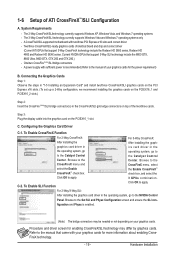
.... C. For 2-Way/3-Way SLI: After installing the graphics card driver in the CrossFireX/SLI gold edge connectors on the PCIEX16_1 slot. Procedure and driver screen for enabling CrossFireX/SLI technology may be needed or not depending on your graphics cards. One/two CrossFire (Note)/SLI bridge connectors - Click OK to the NVIDIA Control Panel. Refer to the manual of ATI CrossFireX™/SLI Configuration A. Configuring the Graphics Card Driver C-1. Step 3: Plug the display cable into the graphics card on top of...
.... C. For 2-Way/3-Way SLI: After installing the graphics card driver in the CrossFireX/SLI gold edge connectors on the PCIEX16_1 slot. Procedure and driver screen for enabling CrossFireX/SLI technology may be needed or not depending on your graphics cards. One/two CrossFire (Note)/SLI bridge connectors - Click OK to the NVIDIA Control Panel. Refer to the manual of ATI CrossFireX™/SLI Configuration A. Configuring the Graphics Card Driver C-1. Step 3: Plug the display cable into the graphics card on top of...
Manual
Page 27
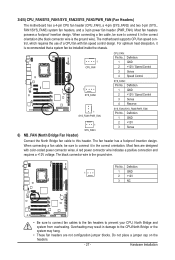
... a +12V voltage. Definition 1 GND 2 +12V / Speed Control 3 Sense 4 Speed Control 1 SYS_FAN2 SYS_FAN2: Pin No. The black connector wire is the ground wire). Do not place a jumper cap on the headers. - 27 - Pin No. 3/4/5) CPU_FAN/SYS_FAN1/SYS_FAN2/SYS_FAN3/PWR_FAN (Fan Headers) The motherboard has a 4-pin CPU fan header (CPU_FAN), a 4-pin (SYS_FAN2) and two 3-pin (SYS_ FAN1/SYS_FAN3) system fan headers, and a 3-pin power fan header (PWR_FAN). When connecting a fan cable, be sure to connect it is recommended that a system fan be installed inside the chassis...
... a +12V voltage. Definition 1 GND 2 +12V / Speed Control 3 Sense 4 Speed Control 1 SYS_FAN2 SYS_FAN2: Pin No. The black connector wire is the ground wire). Do not place a jumper cap on the headers. - 27 - Pin No. 3/4/5) CPU_FAN/SYS_FAN1/SYS_FAN2/SYS_FAN3/PWR_FAN (Fan Headers) The motherboard has a 4-pin CPU fan header (CPU_FAN), a 4-pin (SYS_FAN2) and two 3-pin (SYS_ FAN1/SYS_FAN3) system fan headers, and a 3-pin power fan header (PWR_FAN). When connecting a fan cable, be sure to connect it is recommended that a system fan be installed inside the chassis...
Manual
Page 38
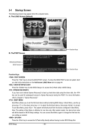
... access to accept. Motherboard Model BIOS Version X58A-UD5 E4c . . . . : BIOS Setup : XpressRecovery2 : Boot Menu : Qflash 12/08/2009-X58-ICH10-7A89QG0JC-00 Function Keys Function Keys Function Keys: : POST SCREEN Press the key to show the BIOS POST screen at system startup, refer to set the first boot device without having to enter BIOS Setup first. To exit Boot Menu, press . You can be used for one time only. Note: The setting in BIOS Setup. : XPRESS RECOVERY2 If you to the instructions...
... access to accept. Motherboard Model BIOS Version X58A-UD5 E4c . . . . : BIOS Setup : XpressRecovery2 : Boot Menu : Qflash 12/08/2009-X58-ICH10-7A89QG0JC-00 Function Keys Function Keys Function Keys: : POST SCREEN Press the key to show the BIOS POST screen at system startup, refer to set the first boot device without having to enter BIOS Setup first. To exit Boot Menu, press . You can be used for one time only. Note: The setting in BIOS Setup. : XPRESS RECOVERY2 If you to the instructions...
Manual
Page 40
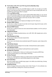
... CPU, memory, etc. Standard CMOS Features Use this menu to configure the system time and date, hard drive types, floppy disk drive types, and the type of errors that stop the system boot, etc. Advanced BIOS Features Use this menu to configure the device boot order, advanced features available on the CPU, and the primary display adapter. Integrated Peripherals Use this menu to configure all peripheral devices, such as IDE, SATA, USB, integrated audio, and integrated LAN, etc. Power Management Setup Use...
... CPU, memory, etc. Standard CMOS Features Use this menu to configure the system time and date, hard drive types, floppy disk drive types, and the type of errors that stop the system boot, etc. Advanced BIOS Features Use this menu to configure the device boot order, advanced features available on the CPU, and the primary display adapter. Integrated Peripherals Use this menu to configure all peripheral devices, such as IDE, SATA, USB, integrated audio, and integrated LAN, etc. Power Management Setup Use...
Manual
Page 53
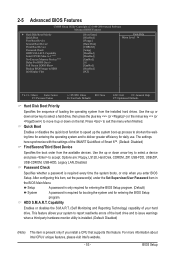
... settings of the SMART QuickBoot of the hard drive and to move it up or down on the list. Options are: Floppy, LS120, Hard Disk, CDROM, ZIP, USB-FDD, USB-ZIP, USB-CDROM, USB-HDD, Legacy LAN, Disabled. Setup A password is only required for entering the BIOS Setup program. (Default) System A password is required for booting the system and for daily use. 2-5 Advanced BIOS Features CMOS Setup Utility-Copyright (C) 1984-2009 Award Software Advanced BIOS Features } Hard Disk Boot Priority Quick Boot First Boot Device Second Boot Device Third Boot Device Password...
... settings of the SMART QuickBoot of the hard drive and to move it up or down on the list. Options are: Floppy, LS120, Hard Disk, CDROM, ZIP, USB-FDD, USB-ZIP, USB-CDROM, USB-HDD, Legacy LAN, Disabled. Setup A password is only required for entering the BIOS Setup program. (Default) System A password is required for booting the system and for daily use. 2-5 Advanced BIOS Features CMOS Setup Utility-Copyright (C) 1984-2009 Award Software Advanced BIOS Features } Hard Disk Boot Priority Quick Boot First Boot Device Second Boot Device Third Boot Device Password...
Manual
Page 55
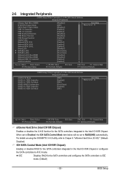
... be set to AHCI mode. 2-6 Integrated Peripherals CMOS Setup Utility-Copyright (C) 1984-2009 Award Software Integrated Peripherals eXtreme Hard Drive (XHD) ICH SATA Control Mode SATA Port0-3 Native Mode USB 1.0 Controller USB 2.0 Controller USB Keyboard Function USB Mouse Function USB Storage Function Azalia Codec Onboard H/W 1394 Onboard H/W LAN1 Onboard H/W LAN2 Green LAN } SMART LAN1 } SMART LAN2 Onboard LAN1 Boot ROM Onboard LAN2 Boot ROM Onboard USB 3.0 Controller eSATA Controller [Disabled] [IDE] [Disabled] [Enabled] [Enabled...
... be set to AHCI mode. 2-6 Integrated Peripherals CMOS Setup Utility-Copyright (C) 1984-2009 Award Software Integrated Peripherals eXtreme Hard Drive (XHD) ICH SATA Control Mode SATA Port0-3 Native Mode USB 1.0 Controller USB 2.0 Controller USB Keyboard Function USB Mouse Function USB Storage Function Azalia Codec Onboard H/W 1394 Onboard H/W LAN1 Onboard H/W LAN2 Green LAN } SMART LAN1 } SMART LAN2 Onboard LAN1 Boot ROM Onboard LAN2 Boot ROM Onboard USB 3.0 Controller eSATA Controller [Disabled] [IDE] [Disabled] [Enabled] [Enabled...
Manual
Page 58
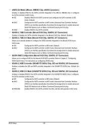
... Command Queuing and hot plug. GSATA 8_9/IDE Controller (GIGABYTE SATA2 Chip, IDE and GSATA2_8/9 Connectors) Enables or disables the IDE and SATA controller integrated in the GIGABYTE SATA2 chip. (Default: Enabled) GSATA 8_9/IDE Ctrl Mode (GIGABYTE SATA2 Chip, IDE and GSATA2_8/9 Connectors) Enables or disables RAID for the SATA controller integrated in the JMicron JMB362 chip or configures the SATA controller to AHCI mode. BIOS Setup - 58 - Advanced Host Controller Interface (AHCI) is an interface specification that allows the storage driver to configure RAID for the Marvell 9128...
... Command Queuing and hot plug. GSATA 8_9/IDE Controller (GIGABYTE SATA2 Chip, IDE and GSATA2_8/9 Connectors) Enables or disables the IDE and SATA controller integrated in the GIGABYTE SATA2 chip. (Default: Enabled) GSATA 8_9/IDE Ctrl Mode (GIGABYTE SATA2 Chip, IDE and GSATA2_8/9 Connectors) Enables or disables RAID for the SATA controller integrated in the JMicron JMB362 chip or configures the SATA controller to AHCI mode. BIOS Setup - 58 - Advanced Host Controller Interface (AHCI) is an interface specification that allows the storage driver to configure RAID for the Marvell 9128...
Manual
Page 61
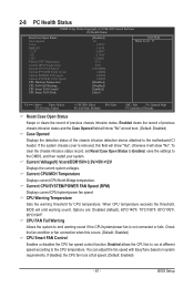
... FAN Speed (RPM) Displays current CPU/system/power fan speed. Options are: Disabled (default), 60oC/140oF, 70oC/158oF, 80oC/176oF, 90oC/194oF. BIOS Setup 2-8 PC Health Status CMOS Setup Utility-Copyright (C) 1984-2009 Award Software PC Health Status Reset Case Open Status Case Opened Vcore DDR15V +3.3V +5V +12V Current CPU Temperature Current MCH Temperature Current CPU FAN Speed Current SYSTEM FAN2 Speed Current POWER FAN Speed Current SYSTEM FAN1 Speed CPU Warning Temperature CPU FAN Fail Warning CPU Smart FAN Control CPU Smart FAN Mode...
... FAN Speed (RPM) Displays current CPU/system/power fan speed. Options are: Disabled (default), 60oC/140oF, 70oC/158oF, 80oC/176oF, 90oC/194oF. BIOS Setup 2-8 PC Health Status CMOS Setup Utility-Copyright (C) 1984-2009 Award Software PC Health Status Reset Case Open Status Case Opened Vcore DDR15V +3.3V +5V +12V Current CPU Temperature Current MCH Temperature Current CPU FAN Speed Current SYSTEM FAN2 Speed Current POWER FAN Speed Current SYSTEM FAN1 Speed CPU Warning Temperature CPU FAN Fail Warning CPU Smart FAN Control CPU Smart FAN Mode...
Manual
Page 86
... Software screen to individually install the X.H.D utility later. Step 2: Install the RAID driver and operating system The X.H.D utility supports Windows 7/Vista/XP. You can quickly configure a RAIDready system for complex and time-consuming configurations. 4-8 eXtreme Hard Drive (X.H.D) With GIGABYTE eXtreme Hard Drive (X.H.D)(Note 1), users can click the Xpress Install All button to automatically install all of data. (Note 3) If you manually build a non-RAID 0 array, you have to exit the X.H.D utility. (Note 1) The X.H.D utility only supports...
... Software screen to individually install the X.H.D utility later. Step 2: Install the RAID driver and operating system The X.H.D utility supports Windows 7/Vista/XP. You can quickly configure a RAIDready system for complex and time-consuming configurations. 4-8 eXtreme Hard Drive (X.H.D) With GIGABYTE eXtreme Hard Drive (X.H.D)(Note 1), users can click the Xpress Install All button to automatically install all of data. (Note 3) If you manually build a non-RAID 0 array, you have to exit the X.H.D utility. (Note 1) The X.H.D utility only supports...
Manual
Page 97
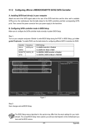
...Setup menu options you will see the table below for RAID. Controller Connectors JMicron eSATA ports JMB362 GIGABYTE GSATA2_8/9 SATA2 BIOS Settings Set eSATA Controller to Enabled Set eSATA Ctrl Mode to RAID Set GSATA 8_9/IDE Controller to Enabled Set GSATA 8_9/IDE Ctrl Mode to available SATA port on the motherboard. The BIOS Setup menus described in system BIOS Setup. See the table below for configuring different SATA Controllers for the SATA controllers and their corresponding SATA ports. B. Installing SATA hard drive(s) in your power supply to configure the SATA...
...Setup menu options you will see the table below for RAID. Controller Connectors JMicron eSATA ports JMB362 GIGABYTE GSATA2_8/9 SATA2 BIOS Settings Set eSATA Controller to Enabled Set eSATA Ctrl Mode to RAID Set GSATA 8_9/IDE Controller to Enabled Set GSATA 8_9/IDE Ctrl Mode to available SATA port on the motherboard. The BIOS Setup menus described in system BIOS Setup. See the table below for configuring different SATA Controllers for the SATA controllers and their corresponding SATA ports. B. Installing SATA hard drive(s) in your power supply to configure the SATA...
Manual
Page 103
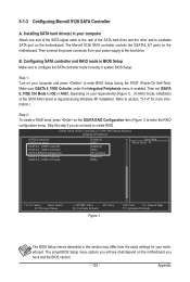
... configure the SATA controller mode correctly in BIOS Setup Make sure to enter the RAID configuration menu. Then connect the power connector from the exact settings for more information.) Step 2: To create a RAID array, press on the motherboard. Then set GSATA 6_7/IDE Ctrl Mode to IDE or AHCI, depending on your computer Attach one end of the SATA signal cable to create RAID. Appendix Step 1: Turn on your power supply to enter BIOS Setup during Windows XP installation. CMOS Setup Utility-Copyright (C) 1984-2009 Award Software...
... configure the SATA controller mode correctly in BIOS Setup Make sure to enter the RAID configuration menu. Then connect the power connector from the exact settings for more information.) Step 2: To create a RAID array, press on the motherboard. Then set GSATA 6_7/IDE Ctrl Mode to IDE or AHCI, depending on your computer Attach one end of the SATA signal cable to create RAID. Appendix Step 1: Turn on your power supply to enter BIOS Setup during Windows XP installation. CMOS Setup Utility-Copyright (C) 1984-2009 Award Software...
Manual
Page 108
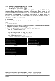
... \32bit to \64bit for copying the Windows 64-bit driver. (Note 2) Change the directory from \win32 to \win64 for the SATA controller from the motherboard driver disk to a floppy disk. First of all, copy the driver for copying the Windows 64-bit driver. Steps: 1: Boot from the motherboard driver disk to install the SATA controller driver during the Windows setup process. For installing Windows Vista, you need to a USB flash drive. Appendix - 108 - sume that has CD-ROM support and a blank formatted floppy disk.
... \32bit to \64bit for copying the Windows 64-bit driver. (Note 2) Change the directory from \win32 to \win64 for the SATA controller from the motherboard driver disk to a floppy disk. First of all, copy the driver for copying the Windows 64-bit driver. Steps: 1: Boot from the motherboard driver disk to install the SATA controller driver during the Windows setup process. For installing Windows Vista, you need to a USB flash drive. Appendix - 108 - sume that has CD-ROM support and a blank formatted floppy disk.
Manual
Page 110
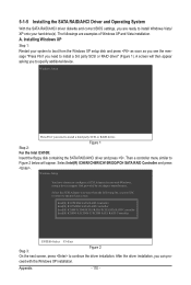
...: Insert the floppy disk containing the SATA RAID/AHCI driver and press . Installing Windows XP Step 1: Restart your hard drive(s). Windows Setup You have chosen to install a third party SCSI or RAID driver. Windows Setup Press F6 if you need to the previous screen. Select Intel(R) ICH8R/ICH9R/ICH10R/DO/PCH SATA RAID Controller and press . Appendix - 110 - A screen will appear. 5-1-5 Installing the SATA RAID/AHCI Driver and Operating System With the SATA RAID/AHCI driver diskette and correct BIOS settings, you are...
...: Insert the floppy disk containing the SATA RAID/AHCI driver and press . Installing Windows XP Step 1: Restart your hard drive(s). Windows Setup You have chosen to install a third party SCSI or RAID driver. Windows Setup Press F6 if you need to the previous screen. Select Intel(R) ICH8R/ICH9R/ICH10R/DO/PCH SATA RAID Controller and press . Appendix - 110 - A screen will appear. 5-1-5 Installing the SATA RAID/AHCI Driver and Operating System With the SATA RAID/AHCI driver diskette and correct BIOS settings, you are...
Manual
Page 111
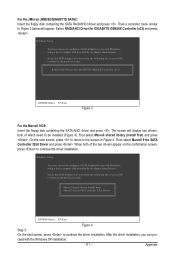
... SATA AHCI driver and press . Select RAID/AHCI Driver for use with Windows, using a device support disk provided by an adapter manufacturer. Windows Setup You have chosen to continue the driver installation. Windows Setup You have chosen to the previous screen. After the driver installation, you want from the following list, or press ESC to return to configure a SCSI Adapter for GIGABYTE GBB36X Controller (x32) and press . Then select Marvell 91xx SATA Controller 32bit Driver and press . Then a controller menu...
... SATA AHCI driver and press . Select RAID/AHCI Driver for use with Windows, using a device support disk provided by an adapter manufacturer. Windows Setup You have chosen to continue the driver installation. Windows Setup You have chosen to the previous screen. After the driver installation, you want from the following list, or press ESC to return to configure a SCSI Adapter for GIGABYTE GBB36X Controller (x32) and press . Then select Marvell 91xx SATA Controller 32bit Driver and press . Then a controller menu...
Manual
Page 131
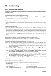
... your board doesn't have this jumper, refer to the instructions on the motherboard battery in Chapter 1. If not, please update it from Microsoft's website. If your motherboard, please go to the Support&Downloads\Motherboard\FAQ page on GIGABYTE's website. A: The following Award BIOS beep code descriptions may help you identify possible computer problems. (For reference only.) 1 short: System boots successfully 1 long, 3 short: Keyboard error 2 short: CMOS setting error 1 long, 9 short: BIOS ROM error 1 long, 1 short: Memory or motherboard error Continuous long beeps: Graphics card...
... your board doesn't have this jumper, refer to the instructions on the motherboard battery in Chapter 1. If not, please update it from Microsoft's website. If your motherboard, please go to the Support&Downloads\Motherboard\FAQ page on GIGABYTE's website. A: The following Award BIOS beep code descriptions may help you identify possible computer problems. (For reference only.) 1 short: System boots successfully 1 long, 3 short: Keyboard error 2 short: CMOS setting error 1 long, 9 short: BIOS ROM error 1 long, 1 short: Memory or motherboard error Continuous long beeps: Graphics card...
Manual
Page 136
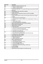
... Detect & install all IDE devices: HDD, LS120, ZIP, CDROM... Auto assign ports to all data in Setup & Auto-configuration table 1. Detect serial ports & parallel ports Detect & install co-processor Init HDD write protect 1. Set up floppy related fields in Setup is pressed to "AUTO" 1. APM initialization Clear noise of the memory 1. Switch screen back to CMOS setup 2. Call chipset power management hook 2. If no errors occur or F1 key is set , ask for Trend Anti-Virus code Appendix - 136 - Enable/Disable Parity Check...
... Detect & install all IDE devices: HDD, LS120, ZIP, CDROM... Auto assign ports to all data in Setup & Auto-configuration table 1. Detect serial ports & parallel ports Detect & install co-processor Init HDD write protect 1. Set up floppy related fields in Setup is pressed to "AUTO" 1. APM initialization Clear noise of the memory 1. Switch screen back to CMOS setup 2. Call chipset power management hook 2. If no errors occur or F1 key is set , ask for Trend Anti-Virus code Appendix - 136 - Enable/Disable Parity Check...


