
Manual
Page 1
... 0 array that before you run the X.H.D utility, back up all motherboard drivers, including the X.H.D utility. B. eXtreme Hard Drive (X.H.D) With GIGABYTE eXtreme Hard Drive (X.H.D)(Note 1), users can use X.H.D to easily add a hard drive into a RAID 0 array that's been created earlier, ...RAID 0. Setting Up a RAID-Ready System Step 1: Configure the system BIOS Enter the system BIOS Setup program, set up a RAID-ready system and configure it for RAID 0 when a new SATA drive is added. Using GIGABYTE eXtreme Hard Drive (X.H.D) Instructions:(Note 2) Before launching X.H.D, make sure the...
... 0 array that before you run the X.H.D utility, back up all motherboard drivers, including the X.H.D utility. B. eXtreme Hard Drive (X.H.D) With GIGABYTE eXtreme Hard Drive (X.H.D)(Note 1), users can use X.H.D to easily add a hard drive into a RAID 0 array that's been created earlier, ...RAID 0. Setting Up a RAID-Ready System Step 1: Configure the system BIOS Enter the system BIOS Setup program, set up a RAID-ready system and configure it for RAID 0 when a new SATA drive is added. Using GIGABYTE eXtreme Hard Drive (X.H.D) Instructions:(Note 2) Before launching X.H.D, make sure the...
Manual
Page 3
... the specifications and features in this : "REV: X.X." For product-related information, check on our website at: http://www.gigabyte.com.tw Identifying Your Motherboard Revision The revision number on our website. The trademarks mentioned in this manual may be reproduced, copied...Technology Guide page on your motherboard revision before updating motherboard BIOS, drivers, or when looking for technical information. No part of this manual may be made by any form or by GIGABYTE without GIGABYTE's prior written permission. All rights reserved. Documentation Classifications ...
... the specifications and features in this : "REV: X.X." For product-related information, check on our website at: http://www.gigabyte.com.tw Identifying Your Motherboard Revision The revision number on our website. The trademarks mentioned in this manual may be reproduced, copied...Technology Guide page on your motherboard revision before updating motherboard BIOS, drivers, or when looking for technical information. No part of this manual may be made by any form or by GIGABYTE without GIGABYTE's prior written permission. All rights reserved. Documentation Classifications ...
Manual
Page 4
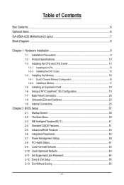
Table of Contents Box Contents...6 Optional Items...6 GA-X58A-UD5 Motherboard Layout 7 Block Diagram...8 Chapter 1 Hardware Installation 9 1-1 Installation Precautions 9 1-2 Product Specifications 10 1-3 Installing the CPU and CPU Cooler 13 1-3-1 ...1-7 Back Panel Connectors 20 1-8 Onboard LEDs and Switches 22 1-9 Internal Connectors 25 Chapter 2 BIOS Setup 37 2-1 Startup Screen 38 2-2 The Main Menu 39 2-3 MB Intelligent Tweaker(M.I.T 41 2-4 Standard CMOS Features 51 2-5 Advanced BIOS Features 53 2-6 Integrated Peripherals 55 2-7 Power Management Setup 59 2-8 PC Health Status 61 ...
Table of Contents Box Contents...6 Optional Items...6 GA-X58A-UD5 Motherboard Layout 7 Block Diagram...8 Chapter 1 Hardware Installation 9 1-1 Installation Precautions 9 1-2 Product Specifications 10 1-3 Installing the CPU and CPU Cooler 13 1-3-1 ...1-7 Back Panel Connectors 20 1-8 Onboard LEDs and Switches 22 1-9 Internal Connectors 25 Chapter 2 BIOS Setup 37 2-1 Startup Screen 38 2-2 The Main Menu 39 2-3 MB Intelligent Tweaker(M.I.T 41 2-4 Standard CMOS Features 51 2-5 Advanced BIOS Features 53 2-6 Integrated Peripherals 55 2-7 Power Management Setup 59 2-8 PC Health Status 61 ...
Manual
Page 5
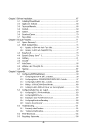
... 4 Unique Features 71 4-1 Xpress Recovery2 71 4-2 BIOS Update Utilities 74 4-2-1 Updating the BIOS with the Q-Flash Utility 74 4-2-2 Updating the BIOS with the @BIOS Utility 77 4-3 EasyTune 6...78 4-4 Dynamic Energy SaverTM... 2 79 4-5 Q-Share...81 4-6 Smart 6™...82 4-7 Auto Green...85 4-8 eXtreme Hard Drive (X.H.D 86 4-9 Teaming 87 Chapter 5 Appendix...89 5-1 Configuring SATA Hard Drive(s 89 5-1-1 Configuring Intel ICH10R SATA Controllers 89 5-1-2 Configuring JMicron JMB362/GIGABYTE...
... 4 Unique Features 71 4-1 Xpress Recovery2 71 4-2 BIOS Update Utilities 74 4-2-1 Updating the BIOS with the Q-Flash Utility 74 4-2-2 Updating the BIOS with the @BIOS Utility 77 4-3 EasyTune 6...78 4-4 Dynamic Energy SaverTM... 2 79 4-5 Q-Share...81 4-6 Smart 6™...82 4-7 Auto Green...85 4-8 eXtreme Hard Drive (X.H.D 86 4-9 Teaming 87 Chapter 5 Appendix...89 5-1 Configuring SATA Hard Drive(s 89 5-1-1 Configuring Intel ICH10R SATA Controllers 89 5-1-2 Configuring JMicron JMB362/GIGABYTE...
Manual
Page 8
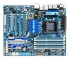
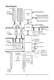
... (100 MHz) JMicron JMB362 Intel® ICH10R 2 PCI Express x1 x1 2 eSATA 3Gb/s 2 SATA 3Gb/s ATA-133/100/66/33 IDE Channel GIGABYTE SATA2 PCI Bus TSB43AB23 CODEC Dual BIOS 6 SATA 3Gb/s 10 USB 2.0/1.1 LPC Bus IT8720 Floppy PS/2 KB/Mouse 3 IEEE 1394a Surround Speaker Out Center/Subwoofer Speaker Out Side Speaker...
... (100 MHz) JMicron JMB362 Intel® ICH10R 2 PCI Express x1 x1 2 eSATA 3Gb/s 2 SATA 3Gb/s ATA-133/100/66/33 IDE Channel GIGABYTE SATA2 PCI Bus TSB43AB23 CODEC Dual BIOS 6 SATA 3Gb/s 10 USB 2.0/1.1 LPC Bus IT8720 Floppy PS/2 KB/Mouse 3 IEEE 1394a Surround Speaker Out Center/Subwoofer Speaker Out Side Speaker...
Manual
Page 12
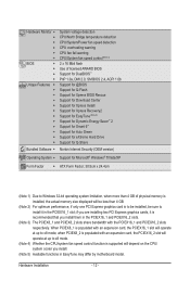
... fan fail warning CPU/System fan speed control (Note 4) 2 x 16 Mbit flash Use of licensed AWARD BIOS Support for DualBIOS™ PnP 1.0a, DMI 2.0, SM BIOS 2.4, ACPI 1.0b Support for @BIOS Support for Q-Flash Support for Xpress BIOS Rescue Support for Download Center Support for Xpress Install Support for Xpress Recovery2 Support for EasyTune...
... fan fail warning CPU/System fan speed control (Note 4) 2 x 16 Mbit flash Use of licensed AWARD BIOS Support for DualBIOS™ PnP 1.0a, DMI 2.0, SM BIOS 2.4, ACPI 1.0b Support for @BIOS Support for Q-Flash Support for Xpress BIOS Rescue Support for Download Center Support for Xpress Install Support for Xpress Recovery2 Support for EasyTune...
Manual
Page 16
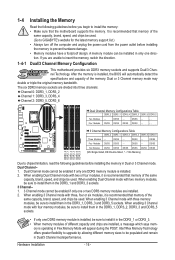
... - - When enabling Dual Channel mode with two or four modules, it is installed, the BIOS will appear during the POST. When enabling 3 Channel mode with three, four or six modules, it is installed, be used . (Go to GIGABYTE's website for the latest memory support list.) • Always turn off the computer and...
... - - When enabling Dual Channel mode with two or four modules, it is installed, the BIOS will appear during the POST. When enabling 3 Channel mode with three, four or six modules, it is installed, be used . (Go to GIGABYTE's website for the latest memory support list.) • Always turn off the computer and...
Manual
Page 18
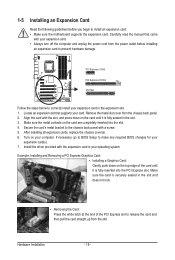
...Turn on the top edge of the card until it is securely seated in the slot. 3. Secure the card's metal bracket to make any required BIOS changes for your expansion card(s). 7. Carefully read the manual that supports your card. Make sure the card is fully inserted into the slot. 4....Press the white latch at the end of the PCI Express slot to prevent hardware damage. Hardware Installation - 18 - If necessary, go to BIOS Setup to the chassis back panel with the slot, and press down on your computer. 1-5 Installing an Expansion Card Read the following guidelines before ...
...Turn on the top edge of the card until it is securely seated in the slot. 3. Secure the card's metal bracket to make any required BIOS changes for your expansion card(s). 7. Carefully read the manual that supports your card. Make sure the card is fully inserted into the slot. 4....Press the white latch at the end of the PCI Express slot to prevent hardware damage. Hardware Installation - 18 - If necessary, go to BIOS Setup to the chassis back panel with the slot, and press down on your computer. 1-5 Installing an Expansion Card Read the following guidelines before ...
Manual
Page 30
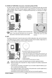
..., the total number of the battery holder, making them short for one minute. (Or use a metal object like a screwdriver to keep the values (such as BIOS configurations, date, and time information) in the power cord and restart your computer. • Always turn off your SATA hard drive. 12) BAT The battery...
..., the total number of the battery holder, making them short for one minute. (Or use a metal object like a screwdriver to keep the values (such as BIOS configurations, date, and time information) in the power cord and restart your computer. • Always turn off your SATA hard drive. 12) BAT The battery...
Manual
Page 31
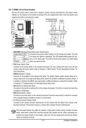
...switch, reset switch, power LED, hard drive activity LED, speaker and etc. When connecting your system using the power switch (refer to Chapter 2, "BIOS Setup," "Power Management Setup," for information about beep codes. • HD (Hard Drive Activity LED, Blue) Connects to the pin assignments below. ...connecting the cables. S1 Blinking tem is in different patterns to the chassis intrusion switch/sensor on when the system is detected, the BIOS may issue beeps in S1 sleep state. Press the reset switch to restart the computer if the computer freezes and fails to perform ...
...switch, reset switch, power LED, hard drive activity LED, speaker and etc. When connecting your system using the power switch (refer to Chapter 2, "BIOS Setup," "Power Management Setup," for information about beep codes. • HD (Hard Drive Activity LED, Blue) Connects to the pin assignments below. ...connecting the cables. S1 Blinking tem is in different patterns to the chassis intrusion switch/sensor on when the system is detected, the BIOS may issue beeps in S1 sleep state. Press the reset switch to restart the computer if the computer freezes and fails to perform ...
Manual
Page 37
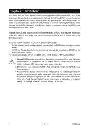
... system instability or other unexpected results. To upgrade the BIOS, use either the GIGABYTE Q-Flash or @BIOS utility. • Q-Flash allows the user to quickly and easily upgrade or back up BIOS without entering the operating system. • @BIOS is potentially risky, if you not flash the BIOS. Refer to Chapter 5, "Troubleshooting," for how to activate...
... system instability or other unexpected results. To upgrade the BIOS, use either the GIGABYTE Q-Flash or @BIOS utility. • Q-Flash allows the user to quickly and easily upgrade or back up BIOS without entering the operating system. • @BIOS is potentially risky, if you not flash the BIOS. Refer to Chapter 5, "Troubleshooting," for how to activate...
Manual
Page 38
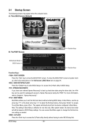
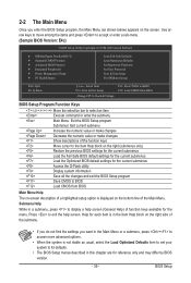
A. Motherboard Model BIOS Version X58A-UD5 E4c . . . . : BIOS Setup : XpressRecovery2 : Boot Menu : Qflash 12/08/2009-X58-ICH10-7A89QG0JC-00 Function Keys Function Keys Function Keys: : POST SCREEN Press the key to show the BIOS POST screen at system startup, refer to enter BIOS Setup first. After system ... will still be used for one time only. 2-1 Startup Screen The following screens may appear when the computer boots. To show the BIOS POST screen. For more information, refer to Chapter 4, "Xpress Recovery2." : BOOT MENU Boot Menu allows you have ever entered Xpress ...
A. Motherboard Model BIOS Version X58A-UD5 E4c . . . . : BIOS Setup : XpressRecovery2 : Boot Menu : Qflash 12/08/2009-X58-ICH10-7A89QG0JC-00 Function Keys Function Keys Function Keys: : POST SCREEN Press the key to show the BIOS POST screen at system startup, refer to enter BIOS Setup first. After system ... will still be used for one time only. 2-1 Startup Screen The following screens may appear when the computer boots. To show the BIOS POST screen. For more information, refer to Chapter 4, "Xpress Recovery2." : BOOT MENU Boot Menu allows you have ever entered Xpress ...
Manual
Page 39
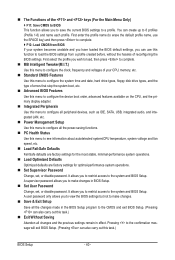
...are for the current submenus Access the Q-Flash utility Display system information Save all the changes and exit the BIOS Setup program Save CMOS to BIOS Load CMOS from BIOS Main Menu Help The on-screen description of a highlighted setup option is not stable as shown below) appears... Without Saving ESC: Quit F8: Q-Flash Select Item F10: Save & Exit Setup Change CPU's Clock & Voltage F11: Save CMOS to BIOS F12: Load CMOS from BIOS BIOS Setup Program Function Keys Move the selection bar to select an item Execute command or enter the submenu Main Menu: Exit the...
...are for the current submenus Access the Q-Flash utility Display system information Save all the changes and exit the BIOS Setup program Save CMOS to BIOS Load CMOS from BIOS Main Menu Help The on-screen description of a highlighted setup option is not stable as shown below) appears... Without Saving ESC: Quit F8: Q-Flash Select Item F10: Save & Exit Setup Change CPU's Clock & Voltage F11: Save CMOS to BIOS F12: Load CMOS from BIOS BIOS Setup Program Function Keys Move the selection bar to select an item Execute command or enter the submenu Main Menu: Exit the...
Manual
Page 40
...the previous settings remain in effect. First enter the profile name (to erase the default profile name, use this function to load the BIOS settings from BIOS If your CPU, memory, etc. Standard CMOS Features Use this menu to configure the system time and date, hard drive ... Password Change, set , or disable password. A supervisor password allows you to make changes. Save & Exit Setup Save all the changes made in BIOS Setup. Set User Password Change, set , or disable password. A user password only allows you wish to load, then press to complete. ...
...the previous settings remain in effect. First enter the profile name (to erase the default profile name, use this function to load the BIOS settings from BIOS If your CPU, memory, etc. Standard CMOS Features Use this menu to configure the system time and date, hard drive ... Password Change, set , or disable password. A supervisor password allows you to make changes. Save & Exit Setup Save all the changes made in BIOS Setup. Set User Password Change, set , or disable password. A user password only allows you wish to load, then press to complete. ...

Manual
Page 41
.... Auto x Command Rate(CMD) - Incorrectly doing overclock/overvoltage may result in damage to CPU, chipset, or memory and reduce the useful life of these components. BIOS Setup Auto >>>>> Channel C x CAS Latency Time 7 Auto x tRCD - Auto } Advanced DRAM Features [Press Enter] Voltage Types Normal Current Load-Line Calibration [Standard] Item Help Menu...
.... Auto x Command Rate(CMD) - Incorrectly doing overclock/overvoltage may result in damage to CPU, chipset, or memory and reduce the useful life of these components. BIOS Setup Auto >>>>> Channel C x CAS Latency Time 7 Auto x tRCD - Auto } Advanced DRAM Features [Press Enter] Voltage Types Normal Current Load-Line Calibration [Standard] Item Help Menu...
Manual
Page 42
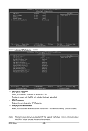
.... The item is present only if a CPU with unlocked clock ratio is present only if you to alter the clock ratio for the installed CPU. BIOS Setup - 42 - For more information about Intel CPUs' unique features, please visit Intel's website. Intel(R) Turbo Boost Tech.
.... The item is present only if a CPU with unlocked clock ratio is present only if you to alter the clock ratio for the installed CPU. BIOS Setup - 42 - For more information about Intel CPUs' unique features, please visit Intel's website. Intel(R) Turbo Boost Tech.

Manual
Page 43
... when the CPU is a more information about Intel CPUs' unique features, please visit Intel's website. - 43 - Virtualization Technology (Note) Enables or disables Intel Virtualization Technology. BIOS Setup With virtualization, one CPU core. 2 Enables only two CPU cores. 3 Enables only three CPU cores. The C3/C6/C7 state is overheated. (Default: Enabled...
... when the CPU is a more information about Intel CPUs' unique features, please visit Intel's website. - 43 - Virtualization Technology (Note) Enables or disables Intel Virtualization Technology. BIOS Setup With virtualization, one CPU core. 2 Enables only two CPU cores. 3 Enables only three CPU cores. The C3/C6/C7 state is overheated. (Default: Enabled...
Manual
Page 44
... Move Enter: Select F5: Previous Values +/-/PU/PD: Value F10: Save F6: Fail-Safe Defaults ESC: Exit F1: General Help F7: Optimized Defaults BIOS Setup - 44 - Uncore Clock Ratio Displays the Uncore clock ratio.
... Move Enter: Select F5: Previous Values +/-/PU/PD: Value F10: Save F6: Fail-Safe Defaults ESC: Exit F1: General Help F7: Optimized Defaults BIOS Setup - 44 - Uncore Clock Ratio Displays the Uncore clock ratio.
Manual
Page 45
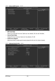
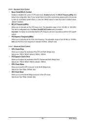
The adjustable range is from 90 MHz to the CPU clock. BIOS Setup The adjustable range is from 100 MHz to 1200 MHz. Auto sets the PCIe clock frequency to standard 100 MHz. (Default: Auto) >>>>> Advanced Clock ...
The adjustable range is from 90 MHz to the CPU clock. BIOS Setup The adjustable range is from 100 MHz to 1200 MHz. Auto sets the PCIe clock frequency to standard 100 MHz. (Default: Auto) >>>>> Advanced Clock ...

Manual
Page 46
...Extreme Memory Profile (X.M.P.) is the normal operating frequency of the memory being used ; Extreme Memory Profile (X.M.P.) (Note) Allows the BIOS to read the SPD data on the CPU being used . (Note) This item appears only if you to set to Profile1...Default: Auto) Memory Frequency(Mhz) The first memory frequency value is set to Disabled, this function. (Default) Profile1 Uses Profile 1 settings. BIOS Setup - 46 - ******** Advanced DRAM Features ******** CMOS Setup Utility-Copyright (C) 1984-2009 Award Software Advanced DRAM Features Performance Enhance Extreme Memory ...
...Extreme Memory Profile (X.M.P.) is the normal operating frequency of the memory being used ; Extreme Memory Profile (X.M.P.) (Note) Allows the BIOS to read the SPD data on the CPU being used . (Note) This item appears only if you to set to Profile1...Default: Auto) Memory Frequency(Mhz) The first memory frequency value is set to Disabled, this function. (Default) Profile1 Uses Profile 1 settings. BIOS Setup - 46 - ******** Advanced DRAM Features ******** CMOS Setup Utility-Copyright (C) 1984-2009 Award Software Advanced DRAM Features Performance Enhance Extreme Memory ...


