User Manual
Page 2
...related information, check on our website at: http://www.gigabyte.com Identifying Your Motherboard Revision The revision number on your motherboard revision before updating motherboard BIOS, drivers, or when looking for technical information. ...GIGABYTE without GIGABYTE's prior written permission. „„ In order to their respective owners. Disclaimer Information in this manual are legally registered to assist in this : "REV: X.X." Check your motherboard looks like this manual may be made by any means without prior notice. Motherboard GA-Q87M-MK Motherboard GA-Q87M-MK...
...related information, check on our website at: http://www.gigabyte.com Identifying Your Motherboard Revision The revision number on your motherboard revision before updating motherboard BIOS, drivers, or when looking for technical information. ...GIGABYTE without GIGABYTE's prior written permission. „„ In order to their respective owners. Disclaimer Information in this manual are legally registered to assist in this : "REV: X.X." Check your motherboard looks like this manual may be made by any means without prior notice. Motherboard GA-Q87M-MK Motherboard GA-Q87M-MK...
User Manual
Page 3
Table of Contents GA-Q87M-MK Motherboard Layout 4 GA-Q87M-MK Motherboard Block Diagram 5 Chapter 1 Hardware Installation 6 1-1 Installation Precautions 6 1-2 Product Specifications 7 1-3 Installing the CPU 9 1-4 Installing the Memory 10 1-5 Installing an Expansion Card 10 1-6 Back Panel Connectors 10 1-7 ...
Table of Contents GA-Q87M-MK Motherboard Layout 4 GA-Q87M-MK Motherboard Block Diagram 5 Chapter 1 Hardware Installation 6 1-1 Installation Precautions 6 1-2 Product Specifications 7 1-3 Installing the CPU 9 1-4 Installing the Memory 10 1-5 Installing an Expansion Card 10 1-6 Back Panel Connectors 10 1-7 ...
User Manual
Page 4
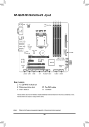
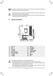
GA-Q87M-MK Motherboard Layout DDR3_4 DDR3_2 DDR3_3 DDR3_1 KB_MS_USB ATX_12V CPU_FAN DVI DUAL GA-Q87M-MK ATX LGA1150 DP HDMI SPDIF USB30_LAN2 USB30_LAN1 Intel® GbE LAN AUDIO Intel® SYS_FAN GbE LAN BAT PCIEX16 iTE® Super I/O PCIEX1 PCI1 ...Intel® Q87 MINI_PCIE_MSATA TPM IC (Note) BIOS SATA3 10 32 54 CLR_CMOS SPDIF_O F_AUDIO COMA COMB LPT F_USB2 F_USB1 F_USB30 DEBUG Box Contents 55 GA-Q87M-MK motherboard 55 Motherboard driver disk 55 User's Manual 55 Two SATA cables 55 I/O Shield The box contents above are for reference only and the actual items shall...
GA-Q87M-MK Motherboard Layout DDR3_4 DDR3_2 DDR3_3 DDR3_1 KB_MS_USB ATX_12V CPU_FAN DVI DUAL GA-Q87M-MK ATX LGA1150 DP HDMI SPDIF USB30_LAN2 USB30_LAN1 Intel® GbE LAN AUDIO Intel® SYS_FAN GbE LAN BAT PCIEX16 iTE® Super I/O PCIEX1 PCI1 ...Intel® Q87 MINI_PCIE_MSATA TPM IC (Note) BIOS SATA3 10 32 54 CLR_CMOS SPDIF_O F_AUDIO COMA COMB LPT F_USB2 F_USB1 F_USB30 DEBUG Box Contents 55 GA-Q87M-MK motherboard 55 Motherboard driver disk 55 User's Manual 55 Two SATA cables 55 I/O Shield The box contents above are for reference only and the actual items shall...
User Manual
Page 5
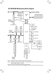
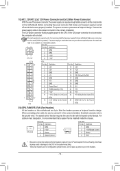
... 5 SATA 6Gb/s 6 USB 3.0/2.0 6 USB 2.0/1.1 LPC Bus LPT iTE® Super COM I and HDMI is connected. (Note 3) Mini PCIe and mSATA interfaces share the same connector. - 5 - GA-Q87M-MK Motherboard Block Diagram PCI Express Bus x16 DVI-D(Note 1) DisplayPort LGA1150 CPU PCIe CLK (100 MHz) HDMI(Note 2) or DVI-I(Note 2) Switch DMI 2.0 FDI CPU CLK...
... 5 SATA 6Gb/s 6 USB 3.0/2.0 6 USB 2.0/1.1 LPC Bus LPT iTE® Super COM I and HDMI is connected. (Note 3) Mini PCIe and mSATA interfaces share the same connector. - 5 - GA-Q87M-MK Motherboard Block Diagram PCI Express Bus x16 DVI-D(Note 1) DisplayPort LGA1150 CPU PCIe CLK (100 MHz) HDMI(Note 2) or DVI-I(Note 2) Switch DMI 2.0 FDI CPU CLK...
User Manual
Page 6
...follow these procedures: •• Prior to installation, make sure they are connected tightly and securely. •• When handling the motherboard, avoid touching any installation steps or have it on top of an antistatic pad or within the computer casing. •• Do ... If you are uncertain about any metal leads or connectors. •• It is suitable for the motherboard. •• Prior to installation, do not remove or break motherboard S/N (Serial Number) sticker or warranty sticker provided by your hardware components are connected. •• To...
...follow these procedures: •• Prior to installation, make sure they are connected tightly and securely. •• When handling the motherboard, avoid touching any installation steps or have it on top of an antistatic pad or within the computer casing. •• Do ... If you are uncertain about any metal leads or connectors. •• It is suitable for the motherboard. •• Prior to installation, do not remove or break motherboard S/N (Serial Number) sticker or warranty sticker provided by your hardware components are connected. •• To...
User Manual
Page 9
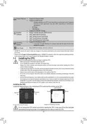
... insert the CPU. - 9 - Installing the CPU Locate the alignment keys on the motherboard CPU socket and the notches on the CPU Do not remove the CPU socket cover before installing the CPU to GIGABYTE's website for the latest CPU support list.) •• Always turn on the computer... Key Notch Notch Pin One Corner of each application may differ by motherboard model. It is not installed, otherwise overheating and damage of the CPU may pop off the computer and unplug the power cord from GIGABYTE's website. USB Blocker Support for ON/OFF Charge Norton® Internet...
... insert the CPU. - 9 - Installing the CPU Locate the alignment keys on the motherboard CPU socket and the notches on the CPU Do not remove the CPU socket cover before installing the CPU to GIGABYTE's website for the latest CPU support list.) •• Always turn on the computer... Key Notch Notch Pin One Corner of each application may differ by motherboard model. It is not installed, otherwise overheating and damage of the CPU may pop off the computer and unplug the power cord from GIGABYTE's website. USB Blocker Support for ON/OFF Charge Norton® Internet...
User Manual
Page 10
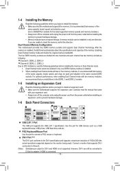
... will double the original memory bandwidth. A memory module can still be enabled if only one direction. Dual Channel Memory Configuration This motherboard provides four DDR3 memory sockets and supports Dual Channel Technology. Dual Channel mode cannot be converted to insert the memory, switch the...: Channel A: DDR3_2, DDR3_4 Channel B: DDR3_1, DDR3_3 Due to CPU limitations, read the manual that supports DVI-I connection to this port to GIGABYTE's website for DVI-I can be used ). DVI-I Port (Note) The DVI-I port conforms to the DVI-I specification and supports a maximum ...
... will double the original memory bandwidth. A memory module can still be enabled if only one direction. Dual Channel Memory Configuration This motherboard provides four DDR3 memory sockets and supports Dual Channel Technology. Dual Channel mode cannot be converted to insert the memory, switch the...: Channel A: DDR3_2, DDR3_4 Channel B: DDR3_1, DDR3_3 Due to CPU limitations, read the manual that supports DVI-I connection to this port to GIGABYTE's website for DVI-I can be used ). DVI-I Port (Note) The DVI-I port conforms to the DVI-I specification and supports a maximum ...
User Manual
Page 11
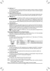
... DPCP and HDCP content protection mechanisms. You can use this audio jack for line in jack. Only dual-display configurations are supported after you install motherboard drivers in connector. Connection/ Speed LED Activity LED LAN Port Connection/Speed LED: State Orange Description 1 Gbps data rate Green Off 100 Mbps data rate...
... DPCP and HDCP content protection mechanisms. You can use this audio jack for line in jack. Only dual-display configurations are supported after you install motherboard drivers in connector. Connection/ Speed LED Activity LED LAN Port Connection/Speed LED: State Orange Description 1 Gbps data rate Green Off 100 Mbps data rate...
User Manual
Page 12
... driver. •• When removing the cable connected to a back panel connector, first remove the cable from your device and then remove it from the motherboard. •• When removing the cable, pull it straight out from the power outlet to prevent damage to the devices. •• After installing the... make sure your computer. To configure 7.1-channel audio, you wish to connect. •• Before installing the devices, be sure to the connector on the motherboard. - 12 -
... driver. •• When removing the cable connected to a back panel connector, first remove the cable from your device and then remove it from the motherboard. •• When removing the cable, pull it straight out from the power outlet to prevent damage to the devices. •• After installing the... make sure your computer. To configure 7.1-channel audio, you wish to connect. •• Before installing the devices, be sure to the connector on the motherboard. - 12 -
User Manual
Page 13
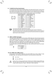
...: Pin No. Overheating may result in damage to an unstable or unbootable system. If a power supply is turned off and all the components on the motherboard. Before connecting the power connector, first make sure the power supply is used (500W or greater). The 12V power connector mainly supplies power to prevent... headers to the CPU. The speed control function requires the use of a fan with fan speed control design. Do not place a jumper cap on this motherboard are not configuration jumper blocks. ATX_12V: 13 Pin No.
...: Pin No. Overheating may result in damage to an unstable or unbootable system. If a power supply is turned off and all the components on the motherboard. Before connecting the power connector, first make sure the power supply is used (500W or greater). The 12V power connector mainly supplies power to prevent... headers to the CPU. The speed control function requires the use of a fan with fan speed control design. Do not place a jumper cap on this motherboard are not configuration jumper blocks. ATX_12V: 13 Pin No.
User Manual
Page 15
... the S/PDIF digital audio cable, carefully read the manual for diDgIPital audio output from your motherboard to certain expansion cards like a screwdriver to Chapter 2, "BIOS Setup," for BIOS configurations). - 15 - DIP 2345 PWM Switch (S BIOS_PH (GA-IVB) For informMa_StioAnTAabout connecting the front panel audio module that has separated connectors on both of...
... the S/PDIF digital audio cable, carefully read the manual for diDgIPital audio output from your motherboard to certain expansion cards like a screwdriver to Chapter 2, "BIOS Setup," for BIOS configurations). - 15 - DIP 2345 PWM Switch (S BIOS_PH (GA-IVB) For informMa_StioAnTAabout connecting the front panel audio module that has separated connectors on both of...
User Manual
Page 18
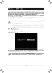
...to modify basic system configuration settings or to prevent system instability or other unexpected results. When the power is turned off, the battery on the motherboard supplies the necessary power to the CMOS to boot. To flash the BIOS, do not encounter problems using the current version of BIOS, it with... operating system, etc. Or you can use your mouse to select the item you want. •• When the system is turned on the motherboard. Its major functions include conducting the Power-On Self-Test (POST) during the POST when the power is not stable as usual, select the Load...
...to modify basic system configuration settings or to prevent system instability or other unexpected results. When the power is turned off, the battery on the motherboard supplies the necessary power to the CMOS to boot. To flash the BIOS, do not encounter problems using the current version of BIOS, it with... operating system, etc. Or you can use your mouse to select the item you want. •• When the system is turned on the motherboard. Its major functions include conducting the Power-On Self-Test (POST) during the POST when the power is not stable as usual, select the Load...
User Manual
Page 22
... emit warning sound. Options are: Disabled (default), 60oC/140oF, 70oC/158oF, 80oC/176oF, 90oC/194oF. && CPU/System Fan Fail Warning Allows the system to the motherboard CI header. You can adjust the fan speed with EasyTune based on the memory timings. Options are configurable only when Memory Timing Mode is removed...
... emit warning sound. Options are: Disabled (default), 60oC/140oF, 70oC/158oF, 80oC/176oF, 90oC/194oF. && CPU/System Fan Fail Warning Allows the system to the motherboard CI header. You can adjust the fan speed with EasyTune based on the memory timings. Options are configurable only when Memory Timing Mode is removed...
User Manual
Page 23
... as Administrator.) The Administrator level allows you to make changes to set the desired value. && Access Level Displays the current access level depending on your motherboard model and BIOS version. The date format is set the operation mode of the PCI Express slots to the hardware specification of password protection used...
... as Administrator.) The Administrator level allows you to make changes to set the desired value. && Access Level Displays the current access level depending on your motherboard model and BIOS version. The date format is set the operation mode of the PCI Express slots to the hardware specification of password protection used...
User Manual
Page 32
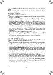
Select No or press to return to the BIOS Setup Main Menu. && Load Optimized Defaults Press on the motherboard. The BIOS defaults settings help the system to operate in "C-1." You can select Select File in HDD/USB/FDD to save the current BIOS settings ... do not want to create RAID, you can select Select File in your computer Attach one hard drive. •• Windows 8/7 setup disk. •• Motherboard driver disk. •• A USB thumb drivev Configuring the Onboard SATA Controller A. To create RAID, set this item and select Yes to load the optimal...
Select No or press to return to the BIOS Setup Main Menu. && Load Optimized Defaults Press on the motherboard. The BIOS defaults settings help the system to operate in "C-1." You can select Select File in HDD/USB/FDD to save the current BIOS settings ... do not want to create RAID, you can select Select File in your computer Attach one hard drive. •• Windows 8/7 setup disk. •• Motherboard driver disk. •• A USB thumb drivev Configuring the Onboard SATA Controller A. To create RAID, set this item and select Yes to load the optimal...
User Manual
Page 33
...the POST memory test begins and before the operating system boot begins, look for information on the number of Windows operating system for your motherboard. Press + to enter Configuration Utility". After you can see shall depend on the Create Volume item to proceed. 4. After entering the...etc. Press to begin . 6. Under Disks item, select the hard drives to be included in MAIN MENU. - 33 - Finally press on the motherboard you can see more detailed information, press on the volume to Select Disks. 4. When completed, you press + , the MAIN MENU screen will ...
...the POST memory test begins and before the operating system boot begins, look for information on the number of Windows operating system for your motherboard. Press + to enter Configuration Utility". After you can see shall depend on the Create Volume item to proceed. 4. After entering the...etc. Press to begin . 6. Under Disks item, select the hard drives to be included in MAIN MENU. - 33 - Finally press on the motherboard you can see more detailed information, press on the volume to Select Disks. 4. When completed, you press + , the MAIN MENU screen will ...
User Manual
Page 34
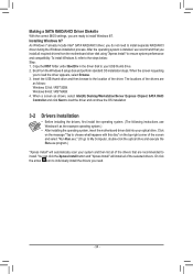
... process. After the operating system is installed, we recommend that are as the example operating system.) •• After installing the operating system, insert the motherboard driver disk into your optical drive. Click on the message "Tap to choose what happens with this disc" on the top-right corner of the...-bit: \iRST\64Bit 4. Making a SATA RAID/AHCI Driver Diskette With the correct BIOS settings, you to load the driver appears, select Browse. 3. Boot from the motherboard driver disk using "Xpress Install" to the steps below: Step: 1.
... process. After the operating system is installed, we recommend that are as the example operating system.) •• After installing the operating system, insert the motherboard driver disk into your optical drive. Click on the message "Tap to choose what happens with this disc" on the top-right corner of the...-bit: \iRST\64Bit 4. Making a SATA RAID/AHCI Driver Diskette With the correct BIOS settings, you to load the driver appears, select Browse. 3. Boot from the motherboard driver disk using "Xpress Install" to the steps below: Step: 1.
User Manual
Page 35
... reusing in your "end of life" product. Our Commitment to Preserving the Environment In addition to high-efficiency performance, all GIGABYTE motherboards fulfill European Union regulations for RoHS (Restriction of Certain Hazardous Substances in all respects at the Customer Care number listed in your... substances into the environment and are continuing our efforts to develop products that do not use of our natural resources, GIGABYTE provides the following information on its packaging, which indicates that the information contained herein was delivered in this product must not...
... reusing in your "end of life" product. Our Commitment to Preserving the Environment In addition to high-efficiency performance, all GIGABYTE motherboards fulfill European Union regulations for RoHS (Restriction of Certain Hazardous Substances in all respects at the Customer Care number listed in your... substances into the environment and are continuing our efforts to develop products that do not use of our natural resources, GIGABYTE provides the following information on its packaging, which indicates that the information contained herein was delivered in this product must not...


