Manual
Page 1
GA-P67A-UD4 LGA1155 socket motherboard for Intel® Core™ i7 processors/ Intel® Core™ i5 processors/Intel® Core™ i3 processors/ Intel® Pentium® processors/Intel® Celeron® processors User's Manual Rev. 1002 12ME-P67AUD4-1002R
GA-P67A-UD4 LGA1155 socket motherboard for Intel® Core™ i7 processors/ Intel® Core™ i5 processors/Intel® Core™ i3 processors/ Intel® Pentium® processors/Intel® Celeron® processors User's Manual Rev. 1002 12ME-P67AUD4-1002R

Manual
Page 2
Motherboard GA-P67A-UD4 Oct. 26, 2010 Motherboard GA-P67A-UD4 Oct. 26, 2010
Motherboard GA-P67A-UD4 Oct. 26, 2010 Motherboard GA-P67A-UD4 Oct. 26, 2010

Manual
Page 3
... specifications and features in this manual may be made by GIGABYTE without GIGABYTE's prior written permission. For example, "REV: 1.0" means the revision of the motherboard is the property of GIGABYTE. Check your motherboard looks like this manual are legally registered to assist in...REV: X.X." For product-related information, check on our website at: http://www.gigabyte.com Identifying Your Motherboard Revision The revision number on your motherboard revision before updating motherboard BIOS, drivers, or when looking for technical information. The trademarks mentioned in ...
... specifications and features in this manual may be made by GIGABYTE without GIGABYTE's prior written permission. For example, "REV: 1.0" means the revision of the motherboard is the property of GIGABYTE. Check your motherboard looks like this manual are legally registered to assist in...REV: X.X." For product-related information, check on our website at: http://www.gigabyte.com Identifying Your Motherboard Revision The revision number on your motherboard revision before updating motherboard BIOS, drivers, or when looking for technical information. The trademarks mentioned in ...

Manual
Page 4
Table of Contents Box Contents...6 Optional Items...6 GA-P67A-UD4 Motherboard Layout 7 GA-P67A-UD4 Motherboard Block Diagram 8 Chapter 1 Hardware Installation 9 1-1 Installation Precautions 9 1-2 Product Specifications 10 1-3 Installing the CPU and CPU Cooler 13 1-3-1 Installing the CPU 13 1-3-2 Installing the CPU Cooler ...
Table of Contents Box Contents...6 Optional Items...6 GA-P67A-UD4 Motherboard Layout 7 GA-P67A-UD4 Motherboard Block Diagram 8 Chapter 1 Hardware Installation 9 1-1 Installation Precautions 9 1-2 Product Specifications 10 1-3 Installing the CPU and CPU Cooler 13 1-3-1 Installing the CPU 13 1-3-2 Installing the CPU Cooler ...

Manual
Page 6
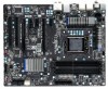
Box Contents GA-P67A-UD4 motherboard Motherboard driver disk User's Manual Quick Installation Guide Four SATA cables I/O Shield One 2-Way SLI bridge connector • The box contents above are subject to change without notice. • The motherboard image is for reference only and the actual items shall depend on the product package you obtain. Optional Items 2-port USB 2.0 bracket (Part No. 12CR1-1UB030-5*R) 2-port SATA power cable (Part No. 12CF1-2SERPW-0*R) COM port cable (Part No. 12CF1-1CM001-3*R) - 6 - The box contents are for reference only.
Box Contents GA-P67A-UD4 motherboard Motherboard driver disk User's Manual Quick Installation Guide Four SATA cables I/O Shield One 2-Way SLI bridge connector • The box contents above are subject to change without notice. • The motherboard image is for reference only and the actual items shall depend on the product package you obtain. Optional Items 2-port USB 2.0 bracket (Part No. 12CR1-1UB030-5*R) 2-port SATA power cable (Part No. 12CF1-2SERPW-0*R) COM port cable (Part No. 12CF1-1CM001-3*R) - 6 - The box contents are for reference only.

Manual
Page 7
For a longer expansion card, use other expansion slots. - 7 - GA-P67A-UD4 Motherboard Layout KB_MS_USB R_SPDIF SYS_FAN1 ATX_12V_2X4 USB_ESATA_2 USB_ESATA_1 Marvell 88SE9128 R_USB30 LGA1155 CPU_FAN PHASE LED PWR_FAN USB_LAN Renesas D720200 AUDIO GA-P67A-UD4 ATX F_AUDIO DDR3_1 DDR3_2 DDR3_3 DDR3_4 Realtek RTL8111E PCIEX1_1 (Note) PCIEX16 PCIEX1_2 CODEC PCIEX1_3 BAT SPDIF_O PCIEX8 iTE PCI1 IT8728 PCI2 COMA SYS_FAN2 F_USB3...
For a longer expansion card, use other expansion slots. - 7 - GA-P67A-UD4 Motherboard Layout KB_MS_USB R_SPDIF SYS_FAN1 ATX_12V_2X4 USB_ESATA_2 USB_ESATA_1 Marvell 88SE9128 R_USB30 LGA1155 CPU_FAN PHASE LED PWR_FAN USB_LAN Renesas D720200 AUDIO GA-P67A-UD4 ATX F_AUDIO DDR3_1 DDR3_2 DDR3_3 DDR3_4 Realtek RTL8111E PCIEX1_1 (Note) PCIEX16 PCIEX1_2 CODEC PCIEX1_3 BAT SPDIF_O PCIEX8 iTE PCI1 IT8728 PCI2 COMA SYS_FAN2 F_USB3...

Manual
Page 8
GA-P67A-UD4 Motherboard Block Diagram PCIe CLK (100 MHz) 1 PCI Express x16 or 2 PCI Express x8 LGA1155 CPU CPU CLK+/- (100 MHz) DDR3 2133/1866/1600/1333/1066 ...
GA-P67A-UD4 Motherboard Block Diagram PCIe CLK (100 MHz) 1 PCI Express x16 or 2 PCI Express x8 LGA1155 CPU CPU CLK+/- (100 MHz) DDR3 2133/1866/1600/1333/1066 ...

Manual
Page 9
...verify that all cables and power connectors of electrostatic discharge (ESD). Hardware Installation Chapter 1 Hardware Installation 1-1 Installation Precautions The motherboard contains numerous delicate electronic circuits and components which can lead to damage to system components as well as physical harm to the ...ESD wrist strap, keep your hands dry and first touch a metal object to eliminate static electricity. • Prior to installing the motherboard, please have a problem related to the use of the product, please consult a certified computer technician. - 9 - Prior to ...
...verify that all cables and power connectors of electrostatic discharge (ESD). Hardware Installation Chapter 1 Hardware Installation 1-1 Installation Precautions The motherboard contains numerous delicate electronic circuits and components which can lead to damage to system components as well as physical harm to the ...ESD wrist strap, keep your hands dry and first touch a metal object to eliminate static electricity. • Prior to installing the motherboard, please have a problem related to the use of the product, please consult a certified computer technician. - 9 - Prior to ...

Manual
Page 12
... Charge Support for Cloud OC Support for Q-Share Norton Internet Security (OEM version) Operating System w Support for EasyTune * Available functions in EasyTune may differ by motherboard model. Unique Features w w w w w w w w w w w w w w Bundled Software w Support for @BIOS Support for Q-Flash Support ...Windows® 7/Vista/XP Form Factor w ATX Form Factor; 30.5cm x 24.4cm * GIGABYTE reserves the right to make any changes to the product specifications and product-related information without prior notice.
... Charge Support for Cloud OC Support for Q-Share Norton Internet Security (OEM version) Operating System w Support for EasyTune * Available functions in EasyTune may differ by motherboard model. Unique Features w w w w w w w w w w w w w w Bundled Software w Support for @BIOS Support for Q-Flash Support ...Windows® 7/Vista/XP Form Factor w ATX Form Factor; 30.5cm x 24.4cm * GIGABYTE reserves the right to make any changes to the product specifications and product-related information without prior notice.

Manual
Page 13
...the CPU and CPU Cooler Read the following guidelines before installing the CPU to GIGABYTE's website for the peripherals. LGA1155 CPU Socket Alignment Key Alignment Key Pin One...graphics card, memory, hard drive, etc. 1-3-1 Installing the CPU A. Locate the alignment keys on the motherboard CPU socket and the notches on the surface of the CPU may locate the notches on both sides of ... support list.) • Always turn on the computer if the CPU cooler is not recommended that the motherboard supports the CPU. (Go to prevent hardware damage. • Locate the pin one of the CPU ...
...the CPU and CPU Cooler Read the following guidelines before installing the CPU to GIGABYTE's website for the peripherals. LGA1155 CPU Socket Alignment Key Alignment Key Pin One...graphics card, memory, hard drive, etc. 1-3-1 Installing the CPU A. Locate the alignment keys on the motherboard CPU socket and the notches on the surface of the CPU may locate the notches on both sides of ... support list.) • Always turn on the computer if the CPU cooler is not recommended that the motherboard supports the CPU. (Go to prevent hardware damage. • Locate the pin one of the CPU ...

Manual
Page 14
... well. Before installing the CPU, make sure the front end of the socket cover and use the other to correctly install the CPU into the motherboard CPU socket. When replacing the load plate, make sure to turn off the computer and unplug the power cord from the socket with your thumb...
... well. Before installing the CPU, make sure the front end of the socket cover and use the other to correctly install the CPU into the motherboard CPU socket. When replacing the load plate, make sure to turn off the computer and unplug the power cord from the socket with your thumb...

Manual
Page 15
... the contrary, is to install.) Step 3: Place the cooler atop the CPU, aligning the four push pins through the pin holes on the motherboard. Check that the Male and Female push pins are joined closely. (Refer to your CPU cooler installation manual for instructions on the... motherboard. 1-3-2 Installing the CPU Cooler Follow the steps below to correctly install the CPU cooler on the motherboard. (The following procedure uses Intel® boxed cooler as the picture above shows, the installation ...
... the contrary, is to install.) Step 3: Place the cooler atop the CPU, aligning the four push pins through the pin holes on the motherboard. Check that the Male and Female push pins are joined closely. (Refer to your CPU cooler installation manual for instructions on the... motherboard. 1-3-2 Installing the CPU Cooler Follow the steps below to correctly install the CPU cooler on the motherboard. (The following procedure uses Intel® boxed cooler as the picture above shows, the installation ...

Manual
Page 16
A memory module can be used . (Go to GIGABYTE's website for optimum performance. DS/SS DDR3_2 - Hardware Installation -...memory bandwidth. If you begin to insert the memory, switch the direction. 1-4-1 Dual Channel Memory Configuration This motherboard provides four DDR3 memory sockets and supports Dual Channel Technology. DS/SS DS/SS DDR3_3 DS/SS - ...design. The four DDR3 memory sockets are unable to install the memory: • Make sure that the motherboard supports the memory. When enabling Dual Channel mode with two or four memory modules, it is recommended that ...
A memory module can be used . (Go to GIGABYTE's website for optimum performance. DS/SS DDR3_2 - Hardware Installation -...memory bandwidth. If you begin to insert the memory, switch the direction. 1-4-1 Dual Channel Memory Configuration This motherboard provides four DDR3 memory sockets and supports Dual Channel Technology. DS/SS DS/SS DDR3_3 DS/SS - ...design. The four DDR3 memory sockets are unable to install the memory: • Make sure that the motherboard supports the memory. When enabling Dual Channel mode with two or four memory modules, it is recommended that ...

Manual
Page 17
... both ends of the memory, push down on the left, place your memory modules in one direction. Hardware Installation Place the memory module on this motherboard. DDR3 and DDR2 DIMMs are not compatible to each other or DDR DIMMs. Be sure to the memory module. 1-4-2 Installing a Memory Before installing a memory module...
... both ends of the memory, push down on the left, place your memory modules in one direction. Hardware Installation Place the memory module on this motherboard. DDR3 and DDR2 DIMMs are not compatible to each other or DDR DIMMs. Be sure to the memory module. 1-4-2 Installing a Memory Before installing a memory module...

Manual
Page 18
... Slot PCI Slot Follow the steps below to prevent hardware damage. Secure the card's metal bracket to install an expansion card: • Make sure the motherboard supports the expansion card. After installing all expansion cards, replace the chassis cover(s). 6. Install the driver provided with a screw. 5.
... Slot PCI Slot Follow the steps below to prevent hardware damage. Secure the card's metal bracket to install an expansion card: • Make sure the motherboard supports the expansion card. After installing all expansion cards, replace the chassis cover(s). 6. Install the driver provided with a screw. 5.
Manual
Page 19
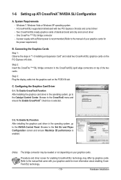
... system, go to the manual that came with two PCI Express x16 slots and correct driver - C-2. Refer to the NVIDIA Control Panel. A CrossFireX/SLI-supported motherboard with your graphics cards for enabling CrossFireX/SLI technology may be needed or not depending on the PCIEX16 slot. 1-6 Setting up ATI CrossFireX™/NVIDIA...
... system, go to the manual that came with two PCI Express x16 slots and correct driver - C-2. Refer to the NVIDIA Control Panel. A CrossFireX/SLI-supported motherboard with your graphics cards for enabling CrossFireX/SLI technology may be needed or not depending on the PCIEX16 slot. 1-6 Setting up ATI CrossFireX™/NVIDIA...

Manual
Page 20
... is occurring LAN Port Off 10 Mbps data rate • When removing the cable connected to a back panel connector, first remove the cable from the motherboard. • When removing the cable, pull it side to side to connect a PS/2 keyboard or mouse. Hardware Installation - 20 -
... is occurring LAN Port Off 10 Mbps data rate • When removing the cable connected to a back panel connector, first remove the cable from the motherboard. • When removing the cable, pull it side to side to connect a PS/2 keyboard or mouse. Hardware Installation - 20 -

Manual
Page 22
..., make sure your devices are compliant with the connectors you wish to connect. • Before installing the devices, be sure to the connector on the motherboard. Hardware Installation - 22 - Unplug the power cord from the power outlet to prevent damage to the devices. • After installing the device and before connecting...
..., make sure your devices are compliant with the connectors you wish to connect. • Before installing the devices, be sure to the connector on the motherboard. Hardware Installation - 22 - Unplug the power cord from the power outlet to prevent damage to the devices. • After installing the device and before connecting...

Manual
Page 23
... Installation If the 12V power connector is used (500W or greater). To meet expansion requirements, it is turned off and all the components on the motherboard. Before connecting the power connector, first make sure the power supply is recommended that a power supply that does not provide the required power, the result...
... Installation If the 12V power connector is used (500W or greater). To meet expansion requirements, it is turned off and all the components on the motherboard. Before connecting the power connector, first make sure the power supply is recommended that a power supply that does not provide the required power, the result...

Manual
Page 24
... of the positive side (+) and the negative side (-) of a CPU fan with an equivalent one. 3/4/5) CPU_FAN/SYS_FAN1/SYS_FAN2/PWR_FAN (Fan Headers) The motherboard has a 4-pin CPU fan header (CPU_FAN), a 4-pin (SYS_FAN2) and a 3-pin (SYS_ FAN1) system fan headers, and a 3-pin power fan header (PWR_FAN).... The motherboard supports CPU fan speed control, which requires the use a metal object like a screwdriver to a low level, or the CMOS values may not be accurate ...
... of the positive side (+) and the negative side (-) of a CPU fan with an equivalent one. 3/4/5) CPU_FAN/SYS_FAN1/SYS_FAN2/PWR_FAN (Fan Headers) The motherboard has a 4-pin CPU fan header (CPU_FAN), a 4-pin (SYS_FAN2) and a 3-pin (SYS_ FAN1) system fan headers, and a 3-pin power fan header (PWR_FAN).... The motherboard supports CPU fan speed control, which requires the use a metal object like a screwdriver to a low level, or the CMOS values may not be accurate ...


