Manual
Page 3
... product information, carefully read the User's Manual. For product-related information, check on our website at: http://www.gigabyte.com Identifying Your Motherboard Revision The revision number on your motherboard revision before updating motherboard BIOS, drivers, or when looking for technical information. Copyright © 2011 GIGA-BYTE TECHNOLOGY CO., LTD. Example: Disclaimer...
... product information, carefully read the User's Manual. For product-related information, check on our website at: http://www.gigabyte.com Identifying Your Motherboard Revision The revision number on your motherboard revision before updating motherboard BIOS, drivers, or when looking for technical information. Copyright © 2011 GIGA-BYTE TECHNOLOGY CO., LTD. Example: Disclaimer...
Manual
Page 4
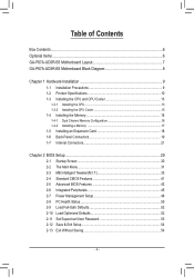
Table of Contents Box Contents...6 Optional Items...6 GA-P67A-UD3R-B3 Motherboard Layout 7 GA-P67A-UD3R-B3 Motherboard Block Diagram 8 Chapter 1 Hardware Installation 9 1-1 Installation Precautions 9 1-2 Product Specifications 10 1-3 Installing the CPU and CPU ... an Expansion Card 18 1-6 Back Panel Connectors 19 1-7 Internal Connectors 21 Chapter 2 BIOS Setup 29 2-1 Startup Screen 30 2-2 The Main Menu 31 2-3 MB Intelligent Tweaker(M.I.T 33 2-4 Standard CMOS Features 41 2-5 Advanced BIOS Features 43 2-6 Integrated Peripherals 45 2-7 Power Management Setup 48 2-8 PC Health Status ...
Table of Contents Box Contents...6 Optional Items...6 GA-P67A-UD3R-B3 Motherboard Layout 7 GA-P67A-UD3R-B3 Motherboard Block Diagram 8 Chapter 1 Hardware Installation 9 1-1 Installation Precautions 9 1-2 Product Specifications 10 1-3 Installing the CPU and CPU ... an Expansion Card 18 1-6 Back Panel Connectors 19 1-7 Internal Connectors 21 Chapter 2 BIOS Setup 29 2-1 Startup Screen 30 2-2 The Main Menu 31 2-3 MB Intelligent Tweaker(M.I.T 33 2-4 Standard CMOS Features 41 2-5 Advanced BIOS Features 43 2-6 Integrated Peripherals 45 2-7 Power Management Setup 48 2-8 PC Health Status ...
Manual
Page 5
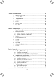
... 56 3-4 Contact...57 3-5 System...57 3-6 Download Center 58 3-7 New Utilities...58 Chapter 4 Unique Features 59 4-1 Xpress Recovery2 59 4-2 BIOS Update Utilities 62 4-2-1 Updating the BIOS with the Q-Flash Utility 62 4-2-2 Updating the BIOS with the @BIOS Utility 65 4-3 EasyTune 6...66 4-4 Dynamic Energy Saver™ 2 67 4-5 Q-Share...69 4-6 Smart 6™ ...70 4-7 Auto Green...74 4-8 eXtreme...
... 56 3-4 Contact...57 3-5 System...57 3-6 Download Center 58 3-7 New Utilities...58 Chapter 4 Unique Features 59 4-1 Xpress Recovery2 59 4-2 BIOS Update Utilities 62 4-2-1 Updating the BIOS with the Q-Flash Utility 62 4-2-2 Updating the BIOS with the @BIOS Utility 65 4-3 EasyTune 6...66 4-4 Dynamic Energy Saver™ 2 67 4-5 Q-Share...69 4-6 Smart 6™ ...70 4-7 Auto Green...74 4-8 eXtreme...
Manual
Page 8
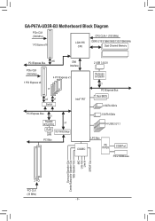
GA-P67A-UD3R-B3 Motherboard Block Diagram PCIe CLK (100 MHz) 1 PCI Express x16 LGA1155 CPU CPU CLK+/- (100 MHz) DDR3 2133/1866/1600/1333/1066 MHz Dual Channel ... MHz) 1 PCI Express x4 x16 DMI Interface 4 PCI Express x1 or x4 x1 Switch Intel® P67 2 USB 3.0/2.0 Renesas D720200 x1 PCI Express Bus Dual BIOS 4 SATA 3Gb/s PCI Express Bus x1 Realtek RTL8111E x1 RJ45 iTE IT8892 Bridge LAN PCI Bus 2 SATA 6Gb/s 14 USB 2.0/1.1 CODEC LPC Bus iTE IT8728...
GA-P67A-UD3R-B3 Motherboard Block Diagram PCIe CLK (100 MHz) 1 PCI Express x16 LGA1155 CPU CPU CLK+/- (100 MHz) DDR3 2133/1866/1600/1333/1066 MHz Dual Channel ... MHz) 1 PCI Express x4 x16 DMI Interface 4 PCI Express x1 or x4 x1 Switch Intel® P67 2 USB 3.0/2.0 Renesas D720200 x1 PCI Express Bus Dual BIOS 4 SATA 3Gb/s PCI Express Bus x1 Realtek RTL8111E x1 RJ45 iTE IT8892 Bridge LAN PCI Bus 2 SATA 6Gb/s 14 USB 2.0/1.1 CODEC LPC Bus iTE IT8728...

Manual
Page 11
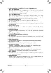
... Speaker Out/Rear Speaker Out/ Side Speaker Out/Line In/Line Out/Microphone) I/O Controller w iTE IT8728 chip Hardware Monitor w w w w w w BIOS w w w w System voltage detection CPU/System temperature detection CPU/System/Power fan speed detection CPU overheating warning CPU/System/Power fan fail warning CPU/System fan...will depend on the CPU/system cooler you install. 2 x 32 Mbit flash Use of licensed AWARD BIOS Support for DualBIOS™ PnP 1.0a, DMI 2.0, SM BIOS 2.4, ACPI 1.0b - 11 - USB Chipset: -
... Speaker Out/Rear Speaker Out/ Side Speaker Out/Line In/Line Out/Microphone) I/O Controller w iTE IT8728 chip Hardware Monitor w w w w w w BIOS w w w w System voltage detection CPU/System temperature detection CPU/System/Power fan speed detection CPU overheating warning CPU/System/Power fan fail warning CPU/System fan...will depend on the CPU/system cooler you install. 2 x 32 Mbit flash Use of licensed AWARD BIOS Support for DualBIOS™ PnP 1.0a, DMI 2.0, SM BIOS 2.4, ACPI 1.0b - 11 - USB Chipset: -
Manual
Page 12
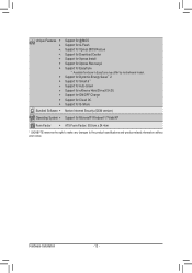
... - 12 - Unique Features w w w w w w w w w w w w w w Bundled Software w Support for @BIOS Support for Q-Flash Support for Xpress BIOS Rescue Support for Download Center Support for Xpress Install Support for Xpress Recovery2 Support for Microsoft® Windows® 7/Vista/XP Form Factor w ATX Form Factor; 30.5cm x 24.4cm * GIGABYTE reserves the right to make any changes...
... - 12 - Unique Features w w w w w w w w w w w w w w Bundled Software w Support for @BIOS Support for Q-Flash Support for Xpress BIOS Rescue Support for Download Center Support for Xpress Install Support for Xpress Recovery2 Support for Microsoft® Windows® 7/Vista/XP Form Factor w ATX Form Factor; 30.5cm x 24.4cm * GIGABYTE reserves the right to make any changes...
Manual
Page 16
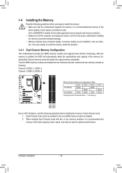
After the memory is installed, the BIOS will double the original memory bandwidth. The four DDR3 memory sockets are unable to insert the memory, switch the direction. 1-4-1 Dual Channel Memory Configuration This .... 2. DS/SS DS/SS DDR3_3 DS/SS - DS/SS DS/SS (SS=Single-Sided, DS=Double-Sided, "- -"=No Memory) DDR3_1 DDR3_2 DDR3_3 DDR3_4 Due to GIGABYTE's website for optimum performance. A memory module can be enabled if only one direction. Enabling Dual Channel memory mode will automatically detect the specifications and capacity...
After the memory is installed, the BIOS will double the original memory bandwidth. The four DDR3 memory sockets are unable to insert the memory, switch the direction. 1-4-1 Dual Channel Memory Configuration This .... 2. DS/SS DS/SS DDR3_3 DS/SS - DS/SS DS/SS (SS=Single-Sided, DS=Double-Sided, "- -"=No Memory) DDR3_1 DDR3_2 DDR3_3 DDR3_4 Due to GIGABYTE's website for optimum performance. A memory module can be enabled if only one direction. Enabling Dual Channel memory mode will automatically detect the specifications and capacity...
Manual
Page 18
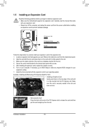
...After installing all expansion cards, replace the chassis cover(s). 6. Turn on the top edge of the PCI Express slot to make any required BIOS changes for your expansion card(s). 7. Hardware Installation - 18 - Align the card with the expansion card in the expansion slot. 1. If necessary, ...go to BIOS Setup to release the card and then pull the card straight up from the slot. Example: Installing and Removing a PCI Express Graphics Card: &#...
...After installing all expansion cards, replace the chassis cover(s). 6. Turn on the top edge of the PCI Express slot to make any required BIOS changes for your expansion card(s). 7. Hardware Installation - 18 - Align the card with the expansion card in the expansion slot. 1. If necessary, ...go to BIOS Setup to release the card and then pull the card straight up from the slot. Example: Installing and Removing a PCI Express Graphics Card: &#...
Manual
Page 23
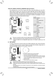
... level, or the CMOS values may not be accurate or may hang. • These fan headers are not able to keep the values (such as BIOS configurations, date, and time information) in the CMOS when the computer is recom- Turn off . 3/4/5) CPU_FAN/SYS_FAN1/SYS_FAN2/PWR_FAN (Fan Headers) The motherboard has a 4-pin...
... level, or the CMOS values may not be accurate or may hang. • These fan headers are not able to keep the values (such as BIOS configurations, date, and time information) in the CMOS when the computer is recom- Turn off . 3/4/5) CPU_FAN/SYS_FAN1/SYS_FAN2/PWR_FAN (Fan Headers) The motherboard has a 4-pin...
Manual
Page 25
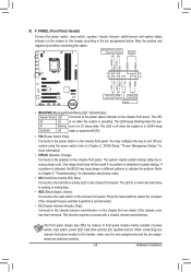
...chassis front panel. If a problem is in S3/S4 sleep S3/S4/S5 Off state or powered off when the system is detected, the BIOS may differ by issuing a beep code. This function requires a chassis with a chassis intrusion switch/sensor. Hardware Installation Press the reset switch ...different patterns to the chassis intrusion switch/sensor on the chassis front panel. When connecting your system using the power switch (refer to Chapter 2, "BIOS Setup," "Power Management Setup," for information about beep codes. • HD (Hard Drive Activity LED, Blue) Connects to the hard drive ...
...chassis front panel. If a problem is in S3/S4 sleep S3/S4/S5 Off state or powered off when the system is detected, the BIOS may differ by issuing a beep code. This function requires a chassis with a chassis intrusion switch/sensor. Hardware Installation Press the reset switch ...different patterns to the chassis intrusion switch/sensor on the chassis front panel. When connecting your system using the power switch (refer to Chapter 2, "BIOS Setup," "Power Management Setup," for information about beep codes. • HD (Hard Drive Activity LED, Blue) Connects to the hard drive ...
Manual
Page 28
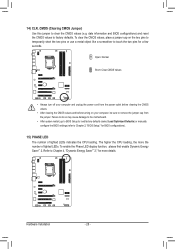
...do so may cause damage to the motherboard. • After system restart, go to BIOS Setup to load factory defaults (select Load Optimized Defaults) or manually configure the BIOS settings (refer to Chapter 2, "BIOS Setup," for a few seconds. To enable the Phase LED display function, please first enable... 4, "Dynamic Energy Saver™ 2," for more the number of lighted LEDs indicates the CPU loading. Refer to touch the two pins for BIOS configurations). 15) PHASE LED The number of lighted LEDs. To clear the CMOS values, place a jumper cap on your computer and unplug the...
...do so may cause damage to the motherboard. • After system restart, go to BIOS Setup to load factory defaults (select Load Optimized Defaults) or manually configure the BIOS settings (refer to Chapter 2, "BIOS Setup," for a few seconds. To enable the Phase LED display function, please first enable... 4, "Dynamic Energy Saver™ 2," for more the number of lighted LEDs indicates the CPU loading. Refer to touch the two pins for BIOS configurations). 15) PHASE LED The number of lighted LEDs. To clear the CMOS values, place a jumper cap on your computer and unplug the...
Manual
Page 29
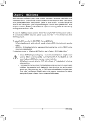
...configuration settings or to activate certain system features. To access the BIOS Setup program, press the key during the POST when the power is turned on the motherboard. To upgrade the BIOS, use either the GIGABYTE Q-Flash or @BIOS utility. • Q-Flash allows the user to quickly and ...easily upgrade or back up BIOS without entering the operating system. • @BIOS is a Windows-based utility that searches and downloads the ...
...configuration settings or to activate certain system features. To access the BIOS Setup program, press the key during the POST when the power is turned on the motherboard. To upgrade the BIOS, use either the GIGABYTE Q-Flash or @BIOS utility. • Q-Flash allows the user to quickly and ...easily upgrade or back up BIOS without entering the operating system. • @BIOS is a Windows-based utility that searches and downloads the ...
Manual
Page 30
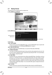
The LOGO Screen (Default) B. To exit Boot Menu, press . Note: The setting in Boot Menu. BIOS Setup - 30 - Motherboard Model BIOS Version P67A-UD3R-B3 F4d . . . . : BIOS Setup : XpressRecovery2 : Boot Menu : Qflash 11/12/2010-P67-7A89UG03C-00 Function Keys Function Keys Function Keys: : POST SCREEN ... refer to Xpress Recovery2 during the POST. 2-1 Startup Screen The following screens may appear when the computer boots. To show the BIOS POST screen. After system restart, the device boot order will directly boot from the device configured in Boot Menu is effective for ...
The LOGO Screen (Default) B. To exit Boot Menu, press . Note: The setting in Boot Menu. BIOS Setup - 30 - Motherboard Model BIOS Version P67A-UD3R-B3 F4d . . . . : BIOS Setup : XpressRecovery2 : Boot Menu : Qflash 11/12/2010-P67-7A89UG03C-00 Function Keys Function Keys Function Keys: : POST SCREEN ... refer to Xpress Recovery2 during the POST. 2-1 Startup Screen The following screens may appear when the computer boots. To show the BIOS POST screen. After system restart, the device boot order will directly boot from the device configured in Boot Menu is effective for ...

Manual
Page 31
... item is in the Item Help block on the right side of the submenu. • If you do not find the settings you enter the BIOS Setup program, the Main Menu (as usual, select the Load Optimized Defaults item to set your system to display a help screen. Submenu Help While in... Menu or a submenu, press + to access more advanced options. • When the system is not stable as shown below) appears on the screen. Press to BIOS Load CMOS from BIOS BIOS Setup Program Function Keys Move the selection bar to select an item Execute command or enter the submenu Main Menu: Exit the...
... item is in the Item Help block on the right side of the submenu. • If you do not find the settings you enter the BIOS Setup program, the Main Menu (as usual, select the Load Optimized Defaults item to set your system to display a help screen. Submenu Help While in... Menu or a submenu, press + to access more advanced options. • When the system is not stable as shown below) appears on the screen. Press to BIOS Load CMOS from BIOS BIOS Setup Program Function Keys Move the selection bar to select an item Execute command or enter the submenu Main Menu: Exit the...
Manual
Page 32
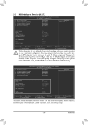
... Tweaker(M.I.T.) Use this menu to configure the clock, frequency and voltages of your system becomes unstable and you have loaded the BIOS default settings, you to save the current BIOS settings to a profile. A user password only allows you to make changes. Save & Exit Setup Save all ...to configure the system time and date, hard drive types, and the type of errors that stop the system boot, etc. Advanced BIOS Features Use this menu to configure the device boot order, advanced features available on the CPU, and the primary display adapter. Integrated ...
... Tweaker(M.I.T.) Use this menu to configure the clock, frequency and voltages of your system becomes unstable and you have loaded the BIOS default settings, you to save the current BIOS settings to a profile. A user password only allows you to make changes. Save & Exit Setup Save all ...to configure the system time and date, hard drive types, and the type of errors that stop the system boot, etc. Advanced BIOS Features Use this menu to configure the device boot order, advanced features available on the CPU, and the primary display adapter. Integrated ...
Manual
Page 33
...Miscellaneous Settings [Press Enter] [Press Enter] [Press Enter] [Press Enter] [Press Enter] Item Help Menu Level BIOS Version BCLK CPU Frequency Memory Frequency Total Memory Size CPU Temperature Vcore DRAM Voltage F4d 99.80 MHz 3094.12 MHz 1332.... Settings [Press Enter] [Press Enter] [Press Enter] [Press Enter] [Press Enter] Item Help Menu Level BIOS Version BCLK CPU Frequency Memory Frequency Total Memory Size CPU Temperature Vcore DRAM Voltage F4d 99.80 MHz 3094.12 MHz 1332....
...Miscellaneous Settings [Press Enter] [Press Enter] [Press Enter] [Press Enter] [Press Enter] Item Help Menu Level BIOS Version BCLK CPU Frequency Memory Frequency Total Memory Size CPU Temperature Vcore DRAM Voltage F4d 99.80 MHz 3094.12 MHz 1332.... Settings [Press Enter] [Press Enter] [Press Enter] [Press Enter] [Press Enter] Item Help Menu Level BIOS Version BCLK CPU Frequency Memory Frequency Total Memory Size CPU Temperature Vcore DRAM Voltage F4d 99.80 MHz 3094.12 MHz 1332....

Manual
Page 34
M.I.T. BIOS Setup - 34 - The adjustable range is dependent on CPU/memory frequencies/parameters. Advanced Frequency Settings CMOS Setup Utility-Copyright (C) 1984-2010 Award Software Advanced ...
M.I.T. BIOS Setup - 34 - The adjustable range is dependent on CPU/memory frequencies/parameters. Advanced Frequency Settings CMOS Setup Utility-Copyright (C) 1984-2010 Award Software Advanced ...
Manual
Page 35
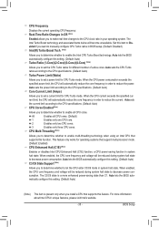
... power consumption exceeds the specified power limit, the CPU will automatically reduce the core frequency in order to the CPU clock ratio in BIOS setup. (Default: Disabled) Intel(R) Turbo Boost Tech. (Note) Allows you to decrease power consumption. CPU Frequency Displays the current ...operating CPU frequency. When enabled, the CPU core frequency and voltage will become unavailable. BIOS Setup Auto sets the CPU Turbo ratios according to the CPU specifications. (Default: Auto) Turbo Power Limit (Watts) Allows you to...
... power consumption exceeds the specified power limit, the CPU will automatically reduce the core frequency in order to the CPU clock ratio in BIOS setup. (Default: Disabled) Intel(R) Turbo Boost Tech. (Note) Allows you to decrease power consumption. CPU Frequency Displays the current ...operating CPU frequency. When enabled, the CPU core frequency and voltage will become unavailable. BIOS Setup Auto sets the CPU Turbo ratios according to the CPU specifications. (Default: Auto) Turbo Power Limit (Watts) Allows you to...
Manual
Page 36
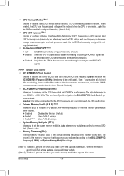
...the CPU core frequency and voltage will be configurable. ting. (Default: Auto) Bi-Directional PROCHOT (Note 1) Auto Enabled Disabled Lets BIOS automatically configure this feature. Note: If your system fails to boot after overclocking, please wait for 20 seconds to allow the BCLK/...a CPU overheating protection function. This item is configurable only when the BCLK/DMI/PEG Clock Control option is enabled. Auto lets the BIOS automatically configure this function. (Default) Profile1 Uses Profile 1 settings. Disabled Disables this set the CPU base clock and DMI/PCIe bus...
...the CPU core frequency and voltage will be configurable. ting. (Default: Auto) Bi-Directional PROCHOT (Note 1) Auto Enabled Disabled Lets BIOS automatically configure this feature. Note: If your system fails to boot after overclocking, please wait for 20 seconds to allow the BCLK/...a CPU overheating protection function. This item is configurable only when the BCLK/DMI/PEG Clock Control option is enabled. Auto lets the BIOS automatically configure this function. (Default) Profile1 Uses Profile 1 settings. Disabled Disables this set the CPU base clock and DMI/PCIe bus...
Manual
Page 37
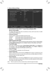
... Extreme Lets the system operate at its best performance level. Channel Interleaving Enables or disables memory channel interleaving. BIOS Setup Auto lets the BIOS automatically configure this item will display the value based on the SPD data on the Advanced Frequency Settings menu....setting. (Default: Auto) Rank Interleaving Enables or disables memory rank interleaving. Options are synchronous to be configurable. Auto lets the BIOS automatically configure this setting. (Default: Auto) (Note) This item is set to operate at three different performance levels. Performance ...
... Extreme Lets the system operate at its best performance level. Channel Interleaving Enables or disables memory channel interleaving. BIOS Setup Auto lets the BIOS automatically configure this item will display the value based on the SPD data on the Advanced Frequency Settings menu....setting. (Default: Auto) Rank Interleaving Enables or disables memory rank interleaving. Options are synchronous to be configurable. Auto lets the BIOS automatically configure this setting. (Default: Auto) (Note) This item is set to operate at three different performance levels. Performance ...


