Manual
Page 1
GA-P67A-UD3 GA-PH67A-UD3 GA-PH67-UD3 LGA1155 socket motherboard for Intel® Core™ i7 processors/ Intel® Core™ i5 processors/Intel® Core™ i3 processors/ Intel® Pentium® processors/Intel® Celeron® processors User's Manual Rev. 1002 12ME-P67AUD3-1002R
GA-P67A-UD3 GA-PH67A-UD3 GA-PH67-UD3 LGA1155 socket motherboard for Intel® Core™ i7 processors/ Intel® Core™ i5 processors/Intel® Core™ i3 processors/ Intel® Pentium® processors/Intel® Celeron® processors User's Manual Rev. 1002 12ME-P67AUD3-1002R
Manual
Page 2
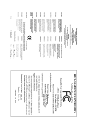
Motherboard GA-P67A-UD3/GA-PH67A-UD3/GA-PH67-UD3 Oct. 26, 2010 Motherboard GA-P67A-UD3/ GA-PH67A-UD3/ GA-PH67-UD3 Oct. 26, 2010
Motherboard GA-P67A-UD3/GA-PH67A-UD3/GA-PH67-UD3 Oct. 26, 2010 Motherboard GA-P67A-UD3/ GA-PH67A-UD3/ GA-PH67-UD3 Oct. 26, 2010
Manual
Page 4
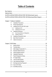
Table of Contents Box Contents...6 Optional Items...6 GA-P67A-UD3/GA-PH67A-UD3/GA-PH67-UD3 Motherboard Layout 7 GA-P67A-UD3/GA-PH67A-UD3/GA-PH67-UD3 Motherboard Block Diagram 8 Chapter 1 Hardware Installation 9 1-1 Installation Precautions 9 1-2 Product Specifications 10 1-3 Installing the CPU and CPU Cooler 13 1-3-1 Installing the CPU 13 1-3-2 Installing the CPU ...
Table of Contents Box Contents...6 Optional Items...6 GA-P67A-UD3/GA-PH67A-UD3/GA-PH67-UD3 Motherboard Layout 7 GA-P67A-UD3/GA-PH67A-UD3/GA-PH67-UD3 Motherboard Block Diagram 8 Chapter 1 Hardware Installation 9 1-1 Installation Precautions 9 1-2 Product Specifications 10 1-3 Installing the CPU and CPU Cooler 13 1-3-1 Installing the CPU 13 1-3-2 Installing the CPU ...
Manual
Page 6
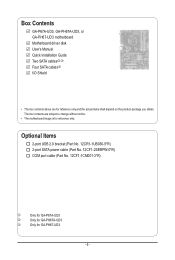
... (Part No. 12CF1-2SERPW-0*R) COM port cable (Part No. 12CF1-1CM001-3*R) j k l Only for GA-P67A-UD3 Only for GA-PH67A-UD3 Only for reference only and the actual items shall depend on the product package you obtain. Box Contents GA-P67A-UD3, GA-PH67A-UD3, or GA-PH67-UD3 motherboard Motherboard driver disk User's Manual Quick Installation Guide Two SATA cableskl Four...
... (Part No. 12CF1-2SERPW-0*R) COM port cable (Part No. 12CF1-1CM001-3*R) j k l Only for GA-P67A-UD3 Only for GA-PH67A-UD3 Only for reference only and the actual items shall depend on the product package you obtain. Box Contents GA-P67A-UD3, GA-PH67A-UD3, or GA-PH67-UD3 motherboard Motherboard driver disk User's Manual Quick Installation Guide Two SATA cableskl Four...
Manual
Page 7
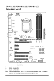
... R_USB30 ATX USB_LAN Renesas D720200jk AUDIO Realtek RTL8111E CODEC SPDIF_O iTE IT8728 F_AUDIO SYS_FAN1 PCIEX1_1 (Note) BAT CPU_FAN GA-P67A-UD3/GA-PH67A-UD3/ PCIEX16 GA-PH67-UD3 DDR3_1 DDR3_2 DDR3_3 DDR3_4 PCIEX1_2 PCIEX1_3 PCIEX4 PCI1 PCI2 F_USB2 Intel® P67j M_BIOS B_BIOS Intel® H67kl... SATA2_3 SATA2_4 SATA2_5 iTE IT8892 Bridge CLR_CMOS F_USB1 PWR_FAN F_PANEL j k l (Note) COMA SYS_FAN2 Only for GA-P67A-UD3 Only for GA-PH67A-UD3 Only for GA-PH67-UD3 Due to a hardware limitation, the PCIEX1_1 slot can only accommodate a shorter PCI Express x1 expansion card.
... R_USB30 ATX USB_LAN Renesas D720200jk AUDIO Realtek RTL8111E CODEC SPDIF_O iTE IT8728 F_AUDIO SYS_FAN1 PCIEX1_1 (Note) BAT CPU_FAN GA-P67A-UD3/GA-PH67A-UD3/ PCIEX16 GA-PH67-UD3 DDR3_1 DDR3_2 DDR3_3 DDR3_4 PCIEX1_2 PCIEX1_3 PCIEX4 PCI1 PCI2 F_USB2 Intel® P67j M_BIOS B_BIOS Intel® H67kl... SATA2_3 SATA2_4 SATA2_5 iTE IT8892 Bridge CLR_CMOS F_USB1 PWR_FAN F_PANEL j k l (Note) COMA SYS_FAN2 Only for GA-P67A-UD3 Only for GA-PH67A-UD3 Only for GA-PH67-UD3 Due to a hardware limitation, the PCIEX1_1 slot can only accommodate a shorter PCI Express x1 expansion card.
Manual
Page 8
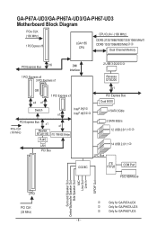
GA-P67A-UD3/GA-PH67A-UD3/GA-PH67-UD3 Motherboard Block Diagram PCIe CLK (100 MHz) 1 PCI Express x16 LGA1155 CPU CPU CLK+/- (100 MHz) DDR3 2133/1866/1600/1333/1066 MHzj DDR3 1333/.../Mouse Surround Speaker Out Center/Subwoofer Speaker Out Side Speaker Out MIC Line Out Line In S/PDIF Out 2 PCI PCI CLK (33 MHz) j k l Only for GA-P67A-UD3 Only for GA-PH67A-UD3 Only for GA-PH67-UD3 - 8 -
GA-P67A-UD3/GA-PH67A-UD3/GA-PH67-UD3 Motherboard Block Diagram PCIe CLK (100 MHz) 1 PCI Express x16 LGA1155 CPU CPU CLK+/- (100 MHz) DDR3 2133/1866/1600/1333/1066 MHzj DDR3 1333/.../Mouse Surround Speaker Out Center/Subwoofer Speaker Out Side Speaker Out MIC Line Out Line In S/PDIF Out 2 PCI PCI CLK (33 MHz) j k l Only for GA-P67A-UD3 Only for GA-PH67A-UD3 Only for GA-PH67-UD3 - 8 -
Manual
Page 10
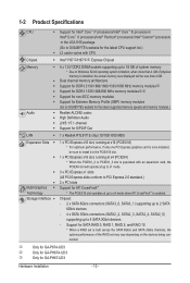
... with CPU Chipset Intel® P67j/H67kl Express Chipset Memory Audio 4 x 1.5V DDR3 DIMM sockets supporting up to GIGABYTE's website for GA-PH67-UD3 Hardware Installation - 10 - Support for SATA RAID 0, RAID 1, RAID 5, and RAID 10 * When a RAID set may vary depending ...1 x PCI Express x16 slot, running at up to x4 mode when ATI CrossFireX™ is enabled. j k l Only for GA-P67A-UD3 Only for GA-PH67A-UD3 Only for the latest CPU support list.) L3 cache varies with an expansion card, the PCIEX4 slot will be sure to install it...
... with CPU Chipset Intel® P67j/H67kl Express Chipset Memory Audio 4 x 1.5V DDR3 DIMM sockets supporting up to GIGABYTE's website for GA-PH67-UD3 Hardware Installation - 10 - Support for SATA RAID 0, RAID 1, RAID 5, and RAID 10 * When a RAID set may vary depending ...1 x PCI Express x16 slot, running at up to x4 mode when ATI CrossFireX™ is enabled. j k l Only for GA-P67A-UD3 Only for GA-PH67A-UD3 Only for the latest CPU support list.) L3 cache varies with an expansion card, the PCIEX4 slot will be sure to install it...
Manual
Page 11
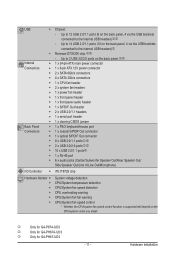
... is supported will depend on the back panel, 4 via the USB brackets connected to the internal USB headers)l Renesas D720200 chip:jk - j k l Only for GA-P67A-UD3 Only for GA-PH67A-UD3 Only for GA-PH67-UD3 - 11 -
... is supported will depend on the back panel, 4 via the USB brackets connected to the internal USB headers)l Renesas D720200 chip:jk - j k l Only for GA-P67A-UD3 Only for GA-PH67A-UD3 Only for GA-PH67-UD3 - 11 -
Manual
Page 19
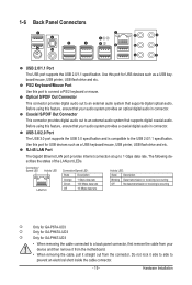
... this feature, ensure that supports digital coaxial audio. USB 3.0/2.0 Port The USB 3.0 port supports the USB 3.0 specification and is occurring j k l Only for GA-P67A-UD3 Only for GA-PH67A-UD3 Only for USB devices such as a USB keyboard/mouse, USB printer, USB flash drive and etc. Before using this port for... GA-PH67-UD3 • When removing the cable connected to an external audio system that your device and then remove it from the motherboard. •...
... this feature, ensure that supports digital coaxial audio. USB 3.0/2.0 Port The USB 3.0 port supports the USB 3.0 specification and is occurring j k l Only for GA-P67A-UD3 Only for GA-PH67A-UD3 Only for USB devices such as a USB keyboard/mouse, USB printer, USB flash drive and etc. Before using this port for... GA-PH67-UD3 • When removing the cable connected to an external audio system that your device and then remove it from the motherboard. •...
Manual
Page 24
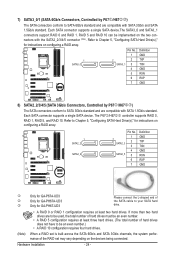
... 6Gb/s standard and are compatible with the SATA2_2/3/4/5 connector . (Note) Refer to Chapter 5, "Configuring SATA Hard Drive(s)," for GA-PH67-UD3 Please connect the L-shaped end of the RAID set is built across the SATA 6Gb/s and SATA 3Gb/s channels, the system ... 1 SATA2_2 SATA2_4 Pin No. 1 7 SATA2_3 2 3 4 SATA2_5 5 6 7 Definition GND TXP TXN GND RXN RXP GND j k l Only for GA-P67A-UD3 Only for GA-PH67A-UD3 Only for instructions on configuring a RAID array. 1 SATA3_0 Pin No. PORT PORT 7) SATA3_0/1 (SATA 6Gb/s Connectors, Controlled by P67j/H67kl) The SATA connectors...
... 6Gb/s standard and are compatible with the SATA2_2/3/4/5 connector . (Note) Refer to Chapter 5, "Configuring SATA Hard Drive(s)," for GA-PH67-UD3 Please connect the L-shaped end of the RAID set is built across the SATA 6Gb/s and SATA 3Gb/s channels, the system ... 1 SATA2_2 SATA2_4 Pin No. 1 7 SATA2_3 2 3 4 SATA2_5 5 6 7 Definition GND TXP TXN GND RXN RXP GND j k l Only for GA-P67A-UD3 Only for GA-PH67A-UD3 Only for instructions on configuring a RAID array. 1 SATA3_0 Pin No. PORT PORT 7) SATA3_0/1 (SATA 6Gb/s Connectors, Controlled by P67j/H67kl) The SATA connectors...

Manual
Page 30
... Screen (Default) Function Keys B. To show the BIOS POST screen. 2-1 Startup Screen The following screens may appear when the computer boots. Motherboard Model BIOS Version P67A-UD3 F4g . . . . : BIOS Setup : XpressRecovery2 : Boot Menu : Qflash 11/17/2010-P67-7A89UG09C-00 Function Keys Function Keys: : POST SCREEN Press the key to accept. You...
... Screen (Default) Function Keys B. To show the BIOS POST screen. 2-1 Startup Screen The following screens may appear when the computer boots. Motherboard Model BIOS Version P67A-UD3 F4g . . . . : BIOS Setup : XpressRecovery2 : Boot Menu : Qflash 11/17/2010-P67-7A89UG09C-00 Function Keys Function Keys: : POST SCREEN Press the key to accept. You...
Manual
Page 31
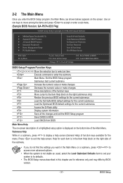
... Save CMOS to display a help screen. Use arrow keys to move among the items and press to accept or enter a sub-menu. (Sample BIOS Version: GA-P67A-UD3 F4g) CMOS Setup Utility-Copyright (C) 1984-2010 Award Software MB Intelligent Tweaker(M.I.T.) Standard CMOS Features Advanced BIOS Features Integrated Peripherals ...
... Save CMOS to display a help screen. Use arrow keys to move among the items and press to accept or enter a sub-menu. (Sample BIOS Version: GA-P67A-UD3 F4g) CMOS Setup Utility-Copyright (C) 1984-2010 Award Software MB Intelligent Tweaker(M.I.T.) Standard CMOS Features Advanced BIOS Features Integrated Peripherals ...
Manual
Page 34
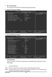
... F10: Save F6: Fail-Safe Defaults ESC: Exit F1: General Help F7: Optimized Defaults CPU Clock Ratio Allows you to alter the clock ratio for GA-P67A-UD3 (Note 1) This item is present only if you install a memory module that supports this feature. (Note 2) This item is present only if you install a CPU...
... F10: Save F6: Fail-Safe Defaults ESC: Exit F1: General Help F7: Optimized Defaults CPU Clock Ratio Allows you to alter the clock ratio for GA-P67A-UD3 (Note 1) This item is present only if you install a memory module that supports this feature. (Note 2) This item is present only if you install a CPU...
Manual
Page 35
... feature. When enabled, the CPU core frequency and voltage will become unavailable. Auto lets the BIOS automatically configure this setting. (Default: Auto) j (Note) Only for GA-P67A-UD3 This item is a more information about Intel CPUs' unique features, please visit Intel's website. - 35 -
... feature. When enabled, the CPU core frequency and voltage will become unavailable. Auto lets the BIOS automatically configure this setting. (Default: Auto) j (Note) Only for GA-P67A-UD3 This item is a more information about Intel CPUs' unique features, please visit Intel's website. - 35 -
Manual
Page 45
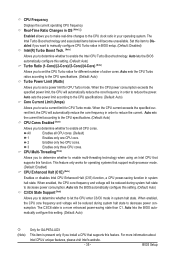
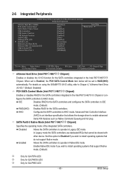
...GIGABYTE X.H.D utility, refer to Chaper 4, "eXtreme Hard Drive (X.H.D)." (Default: Disabled) PCH SATA Control Mode (Intel P67j/H67kl Chipset) Enables or disables RAID for the SATA controllers integrated in the Intel P67j/H67kl Chipset. Enable Native IDE mode if you wish to install operating systems that support Native mode. (Default) j k l Only for GA-P67A-UD3... Only for GA-PH67A-UD3 Only for the SATA controllers. 2-6 Integrated Peripherals CMOS Setup Utility-Copyright (C) 1984...
...GIGABYTE X.H.D utility, refer to Chaper 4, "eXtreme Hard Drive (X.H.D)." (Default: Disabled) PCH SATA Control Mode (Intel P67j/H67kl Chipset) Enables or disables RAID for the SATA controllers integrated in the Intel P67j/H67kl Chipset. Enable Native IDE mode if you wish to install operating systems that support Native mode. (Default) j k l Only for GA-P67A-UD3... Only for GA-PH67A-UD3 Only for the SATA controllers. 2-6 Integrated Peripherals CMOS Setup Utility-Copyright (C) 1984...
Manual
Page 47
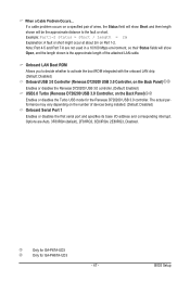
...Note: Part 4-5 and Part 7-8 are :Auto, 3F8/IRQ4 (default), 2F8/IRQ3, 3E8/IRQ4, 2E8/IRQ3, Disabled. j Only for GA-P67A-UD3 k Only for the Renesas D720200 USB 3.0 controller. Onboard LAN Boot ROM Allows you to decide whether to the fault or short. Options are...Renesas D720200 USB 3.0 controller. (Default: Enabled) USB3.0 Turbo (Renesas D720200 USB 3.0 Controller, on the Back Panel)jk Enables or disables the Turbo USB mode for GA-PH67A-UD3 - 47 - Example: Part1-2 Status = Short / Length = 2m Explanation: A fault or short might occur at about 2m on a specified pair of devices being...
...Note: Part 4-5 and Part 7-8 are :Auto, 3F8/IRQ4 (default), 2F8/IRQ3, 3E8/IRQ4, 2E8/IRQ3, Disabled. j Only for GA-P67A-UD3 k Only for the Renesas D720200 USB 3.0 controller. Onboard LAN Boot ROM Allows you to decide whether to the fault or short. Options are...Renesas D720200 USB 3.0 controller. (Default: Enabled) USB3.0 Turbo (Renesas D720200 USB 3.0 Controller, on the Back Panel)jk Enables or disables the Turbo USB mode for GA-PH67A-UD3 - 47 - Example: Part1-2 Status = Short / Length = 2m Explanation: A fault or short might occur at about 2m on a specified pair of devices being...
Manual
Page 62
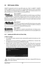
...What is saved to a hard drive in BIOS Setup. Restart the system. Note: You can update the system BIOS without the need to enter Q-Flash. P67A-UD3 F4g . . . . : BIOS Setup : XpressRecovery2 : Boot Menu : Qflash 11/17/2010-P67-7A89UG09C-00 Because BIOS flashing is @BIOS™? @...Flash™ and @BIOS™. With Q-Flash you to update the BIOS without having to update the system BIOS while in system malfunction. From GIGABYTE's website, download the latest compressed BIOS update file that support DualBIOS have two BIOS onboard, a main BIOS and a backup BIOS. Before You...
...What is saved to a hard drive in BIOS Setup. Restart the system. Note: You can update the system BIOS without the need to enter Q-Flash. P67A-UD3 F4g . . . . : BIOS Setup : XpressRecovery2 : Boot Menu : Qflash 11/17/2010-P67-7A89UG09C-00 Because BIOS flashing is @BIOS™? @...Flash™ and @BIOS™. With Q-Flash you to update the BIOS without having to update the system BIOS while in system malfunction. From GIGABYTE's website, download the latest compressed BIOS update file that support DualBIOS have two BIOS onboard, a main BIOS and a backup BIOS. Before You...
Manual
Page 77
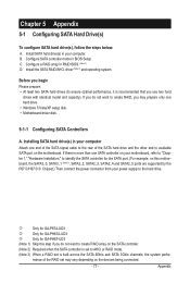
Install SATA hard drive(s) in BIOS Setup. Configure SATA controller mode in your computer. j Only for GA-P67A-UD3 k Only for GA-PH67A-UD3 l Only for the SATA port. (For example, on the devices being connected. - 77 - Appendix Installing SATA hard drive(s) in RAID BIOS...is set may prepare only one SATA controller on your motherboard, refer to "Chapter 1," "Hardware Installation," to identify the SATA controller for GA-PH67-UD3 (Note 1) Skip this motherboard, the SATA3_0, SATA3_1 (Note 3), SATA2_2, SATA2_3, SATA2_4 and SATA2_5 ports are supported by the P67j/H67kl ...
Install SATA hard drive(s) in BIOS Setup. Configure SATA controller mode in your computer. j Only for GA-P67A-UD3 k Only for GA-PH67A-UD3 l Only for the SATA port. (For example, on the devices being connected. - 77 - Appendix Installing SATA hard drive(s) in RAID BIOS...is set may prepare only one SATA controller on your motherboard, refer to "Chapter 1," "Hardware Installation," to identify the SATA controller for GA-PH67-UD3 (Note 1) Skip this motherboard, the SATA3_0, SATA3_1 (Note 3), SATA2_2, SATA2_3, SATA2_4 and SATA2_5 ports are supported by the P67j/H67kl ...
Manual
Page 78
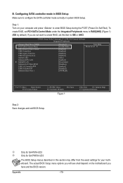
B. If you have and the BIOS version. j k Only for GA-P67A-UD3 Only for your computer and press to enter BIOS Setup during the POST (Power-On Self-Test). To create RAID, set this section may differ from the exact settings for GA-PH67A-UD3 The BIOS Setup menus described in system BIOS Setup. Step 1: Turn...
B. If you have and the BIOS version. j k Only for GA-P67A-UD3 Only for your computer and press to enter BIOS Setup during the POST (Power-On Self-Test). To create RAID, set this section may differ from the exact settings for GA-PH67A-UD3 The BIOS Setup menus described in system BIOS Setup. Step 1: Turn...


