
Manual
Page 1
...load the SATA controller driver first. You can use X.H.D to easily add a hard drive into a RAID 0 array that already exists, users also can click the Xpress Install All button to automatically set up a RAID 0 array. 2. eXtreme Hard Drive (X.H.D) With GIGABYTE eXtreme Hard ...your needs and hardware components. 3. Step 2: Install the RAID driver and operating system The X.H.D utility supports Windows 7/Vista/XP. Using GIGABYTE eXtreme Hard Drive (X.H.D) Instructions:(Note 2) Before launching X.H.D, make sure the new drive is greater than or equal to exit the X.H.D ...
...load the SATA controller driver first. You can use X.H.D to easily add a hard drive into a RAID 0 array that already exists, users also can click the Xpress Install All button to automatically set up a RAID 0 array. 2. eXtreme Hard Drive (X.H.D) With GIGABYTE eXtreme Hard ...your needs and hardware components. 3. Step 2: Install the RAID driver and operating system The X.H.D utility supports Windows 7/Vista/XP. Using GIGABYTE eXtreme Hard Drive (X.H.D) Instructions:(Note 2) Before launching X.H.D, make sure the new drive is greater than or equal to exit the X.H.D ...
Manual
Page 4
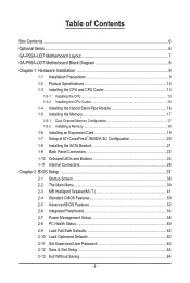
Table of Contents Box Contents...6 Optional Items...6 GA-P55A-UD7 Motherboard Layout 7 GA-P55A-UD7 Motherboard Block Diagram 8 Chapter 1 Hardware Installation 9 1-1 Installation Precautions 9 1-2 Product Specifications 10 1-3 Installing the CPU and CPU Cooler 13 1-3-1 ... Configuration 17 1-5-2 Installing a Memory 18 1-6 Installing an Expansion Card 19 1-7 Setup of ATI CrossFireX™/NVIDIA SLI Configuration 20 1-8 Installing the SATA Bracket 21 1-9 Back Panel Connectors 22 1-10 Onboard LEDs and Buttons 24 1-11 Internal Connectors 26 Chapter 2 BIOS Setup 37 2-1 Startup Screen ...
Table of Contents Box Contents...6 Optional Items...6 GA-P55A-UD7 Motherboard Layout 7 GA-P55A-UD7 Motherboard Block Diagram 8 Chapter 1 Hardware Installation 9 1-1 Installation Precautions 9 1-2 Product Specifications 10 1-3 Installing the CPU and CPU Cooler 13 1-3-1 ... Configuration 17 1-5-2 Installing a Memory 18 1-6 Installing an Expansion Card 19 1-7 Setup of ATI CrossFireX™/NVIDIA SLI Configuration 20 1-8 Installing the SATA Bracket 21 1-9 Back Panel Connectors 22 1-10 Onboard LEDs and Buttons 24 1-11 Internal Connectors 26 Chapter 2 BIOS Setup 37 2-1 Startup Screen ...

Manual
Page 5
......83 4-8 eXtreme Hard Drive (X.H.D 84 4-9 Teaming 85 Chapter 5 Appendix...87 5-1 Configuring SATA Hard Drive(s 87 5-1-1 Configuring Intel P55 SATA Controllers 87 5-1-2 Configuring JMicron JMB362/GIGABYTE SATA2 SATA Controller 95 5-1-3 Configuring Marvell 9128 SATA Controller 101 5-1-4 Making a SATA RAID/AHCI Driver Diskette 106 5-1-5 Installing the SATA RAID/AHCI Driver and Operating System 108 5-2 Configuring Audio Input and Output...
......83 4-8 eXtreme Hard Drive (X.H.D 84 4-9 Teaming 85 Chapter 5 Appendix...87 5-1 Configuring SATA Hard Drive(s 87 5-1-1 Configuring Intel P55 SATA Controllers 87 5-1-2 Configuring JMicron JMB362/GIGABYTE SATA2 SATA Controller 95 5-1-3 Configuring Marvell 9128 SATA Controller 101 5-1-4 Making a SATA RAID/AHCI Driver Diskette 106 5-1-5 Installing the SATA RAID/AHCI Driver and Operating System 108 5-2 Configuring Audio Input and Output...
Manual
Page 6
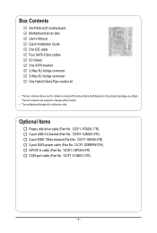
Box Contents GA-P55A-UD7 motherboard Motherboard driver disk User's Manual Quick Installation Guide One IDE cable Four SATA 3Gb/s cables I/O Shield One SATA bracket 2-Way SLI bridge connector 3-Way SLI bridge connector One Hybrid Silent-Pipe module kit • The box contents above are ...Floppy disk drive cable (Part No. 12CF1-1FD001-7*R) 2-port USB 2.0 bracket (Part No. 12CR1-1UB030-5*R) 2-port IEEE 1394a bracket (Part No. 12CF1-1IE008-0*R) 2-port SATA power cable (Part No. 12CF1-2SERPW-0*R) S/PDIF In cable (Part No. 12CR1-1SPDIN-0*R) COM port cable (Part No. 12CF1-1CM001-3*R) - 6 - The box ...
Box Contents GA-P55A-UD7 motherboard Motherboard driver disk User's Manual Quick Installation Guide One IDE cable Four SATA 3Gb/s cables I/O Shield One SATA bracket 2-Way SLI bridge connector 3-Way SLI bridge connector One Hybrid Silent-Pipe module kit • The box contents above are ...Floppy disk drive cable (Part No. 12CF1-1FD001-7*R) 2-port USB 2.0 bracket (Part No. 12CR1-1UB030-5*R) 2-port IEEE 1394a bracket (Part No. 12CF1-1IE008-0*R) 2-port SATA power cable (Part No. 12CF1-2SERPW-0*R) S/PDIF In cable (Part No. 12CR1-1SPDIN-0*R) COM port cable (Part No. 12CF1-1CM001-3*R) - 6 - The box ...
Manual
Page 8
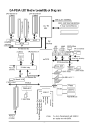
GA-P55A-UD7 Motherboard Block Diagram 2 PCI Express x8 2 PCI Express x8 LGA1156 CPU CPU CLK+/- (133 MHz) DDR3 2200/1333/1066/800 MHz Dual Channel Memory 1 PCI ... NEC x1 x1 PCIe CLK (100 MHz) PEX8608 Bridge x1 x4 PCI Express Bus Marvell 9128 2 SATA 6Gb/s PCI Bus TSB43AB23 3 IEEE 1394a DMI Interface LAN1 LAN2 2 SATA 3Gb/s RJ45 ATA-133/100/66/33 RJ45 GIGABYTE IDE Channel RTL8111D RTL8111D SATA2 Intel® P55 x1 x1 x1 PCIe CLK (100 MHz) PCI...
GA-P55A-UD7 Motherboard Block Diagram 2 PCI Express x8 2 PCI Express x8 LGA1156 CPU CPU CLK+/- (133 MHz) DDR3 2200/1333/1066/800 MHz Dual Channel Memory 1 PCI ... NEC x1 x1 PCIe CLK (100 MHz) PEX8608 Bridge x1 x4 PCI Express Bus Marvell 9128 2 SATA 6Gb/s PCI Bus TSB43AB23 3 IEEE 1394a DMI Interface LAN1 LAN2 2 SATA 3Gb/s RJ45 ATA-133/100/66/33 RJ45 GIGABYTE IDE Channel RTL8111D RTL8111D SATA2 Intel® P55 x1 x1 x1 PCIe CLK (100 MHz) PCI...
Manual
Page 10
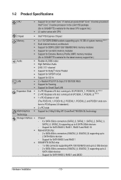
... Express Chipset Memory 4 x 1.5V DDR3 DIMM sockets supporting up to 2 SATA 6Gb/s devices - Support for SATA RAID 0 and RAID 1 GIGABYTE SATA2 chip: - 1 x IDE connector supporting ATA-133/100/66/33 and up to 2 IDE devices - 2 x SATA 3Gb/s connectors (GSATA2_6, GSATA2_7) supporting up to 2 SATA 3Gb/s devices - form to PCI Express 2.0 standard.) 2 x PCI slots...
... Express Chipset Memory 4 x 1.5V DDR3 DIMM sockets supporting up to 2 SATA 6Gb/s devices - Support for SATA RAID 0 and RAID 1 GIGABYTE SATA2 chip: - 1 x IDE connector supporting ATA-133/100/66/33 and up to 2 IDE devices - 2 x SATA 3Gb/s connectors (GSATA2_6, GSATA2_7) supporting up to 2 SATA 3Gb/s devices - form to PCI Express 2.0 standard.) 2 x PCI slots...

Manual
Page 11
... ATX main power connector Connectors w 1 x 8-pin ATX 12V power connector w 1 x floppy disk drive connector w 1 x IDE connector w 8 x SATA 3Gb/s connectors w 2 x SATA 6Gb/s connectors w 1 x CPU fan header w 3 x system fan headers w 1 x power fan header w 1 x Chipset fan header w 1 ...1394a bracket connected to the internal USB headers) NEC D720200F1 chip - TSB43AB23 chip - Support for SATA RAID 0, RAID 1 and JBOD iTE IT8720 chip: - 1 x floppy disk drive connector supporting...
... ATX main power connector Connectors w 1 x 8-pin ATX 12V power connector w 1 x floppy disk drive connector w 1 x IDE connector w 8 x SATA 3Gb/s connectors w 2 x SATA 6Gb/s connectors w 1 x CPU fan header w 3 x system fan headers w 1 x power fan header w 1 x Chipset fan header w 1 ...1394a bracket connected to the internal USB headers) NEC D720200F1 chip - TSB43AB23 chip - Support for SATA RAID 0, RAID 1 and JBOD iTE IT8720 chip: - 1 x floppy disk drive connector supporting...

Manual
Page 21
... of the external enclosure. - 21 - Hardware Installation SATA Bracket SATA Signal Cable SATA Power Cable External SATA Connector Power Connector External SATA Connector The SATA bracket includes one SATA bracket, one SATA signal cable, and one free PCI slot and secure the SATA bracket to the chassis back panel with a screw. For SATA device in external enclosure, you to connect...
... of the external enclosure. - 21 - Hardware Installation SATA Bracket SATA Signal Cable SATA Power Cable External SATA Connector Power Connector External SATA Connector The SATA bracket includes one SATA bracket, one SATA signal cable, and one free PCI slot and secure the SATA bracket to the chassis back panel with a screw. For SATA device in external enclosure, you to connect...

Manual
Page 22
...that your audio system provides a coaxial digital audio in connector. Use this port for an IEEE 1394a device. eSATA/USB Combo Connector This connector supports SATA 3Gb/s and USB 2.0/1.1 specification. The following describes the states of the LAN port LEDs. Before using this feature, ensure that supports digital optical audio.... your device and then remove it from the motherboard. • When removing the cable, pull it side to side to connect an external SATA device; Coaxial S/PDIF Out Connector This connector provides digital audio out to 1 Gbps data rate.
...that your audio system provides a coaxial digital audio in connector. Use this port for an IEEE 1394a device. eSATA/USB Combo Connector This connector supports SATA 3Gb/s and USB 2.0/1.1 specification. The following describes the states of the LAN port LEDs. Before using this feature, ensure that supports digital optical audio.... your device and then remove it from the motherboard. • When removing the cable, pull it side to side to connect an external SATA device; Coaxial S/PDIF Out Connector This connector provides digital audio out to 1 Gbps data rate.

Manual
Page 30
.../s Connectors, Controlled by GIGABYTE SATA2) The SATA connectors conform to SATA 3Gb/s standard and are compatible with SATA 1.5Gb/s standard. G.QBOFM Pin No. Refer to Chapter 5, "Configuring SATA Hard Drive(s)," for instructions on configuring a RAID array. G.QBOFM Pin No. The P55 Chipset supports RAID 0, RAID 1, RAID 5 and RAID 10. The GIGABYTE SATA2 supports RAID 0 and RAID...
.../s Connectors, Controlled by GIGABYTE SATA2) The SATA connectors conform to SATA 3Gb/s standard and are compatible with SATA 1.5Gb/s standard. G.QBOFM Pin No. Refer to Chapter 5, "Configuring SATA Hard Drive(s)," for instructions on configuring a RAID array. G.QBOFM Pin No. The P55 Chipset supports RAID 0, RAID 1, RAID 5 and RAID 10. The GIGABYTE SATA2 supports RAID 0 and RAID...

Manual
Page 31
Refer to keep the values (such as BIOS configurations, date, and time information) in the CMOS when the computer is replaced with SATA 3Gb/s and SATA 1.5Gb/s standards. Replace the battery when the battery voltage drops to a low level, or the CMOS values may not be ...- 31 - Gently remove the battery from the battery holder and wait for instructions on configuring a RAID array. Replace the battery. 4. Each SATA connector supports a single SATA device. The Marvell 9128 supports RAID 0 and RAID 1. You may be an even number. Danger of explosion if the battery is turned off...
Refer to keep the values (such as BIOS configurations, date, and time information) in the CMOS when the computer is replaced with SATA 3Gb/s and SATA 1.5Gb/s standards. Replace the battery when the battery voltage drops to a low level, or the CMOS values may not be ...- 31 - Gently remove the battery from the battery holder and wait for instructions on configuring a RAID array. Replace the battery. 4. Each SATA connector supports a single SATA device. The Marvell 9128 supports RAID 0 and RAID 1. You may be an even number. Danger of explosion if the battery is turned off...

Manual
Page 40
..., advanced features available on the CPU, and the primary display adapter. Integrated Peripherals Use this menu to configure all peripheral devices, such as IDE, SATA, USB, integrated audio, and integrated LAN, etc. Power Management Setup Use this menu to configure all the power-saving functions. PC Health Status...
..., advanced features available on the CPU, and the primary display adapter. Integrated Peripherals Use this menu to configure all peripheral devices, such as IDE, SATA, USB, integrated audio, and integrated LAN, etc. Power Management Setup Use this menu to configure all the power-saving functions. PC Health Status...

Manual
Page 50
... parameters of the three methods below: BIOS Setup - 50 - The date format is 13:0:0. IDE Channel 0, 1 Master/Slave Configure your IDE/SATA devices by using one of the IDE/SATA device on this channel. 2-4 Standard CMOS Features CMOS Setup Utility-Copyright (C) 1984-2009 Award Software Standard CMOS Features Date (mm:dd:yy...
... parameters of the three methods below: BIOS Setup - 50 - The date format is 13:0:0. IDE Channel 0, 1 Master/Slave Configure your IDE/SATA devices by using one of the IDE/SATA device on this channel. 2-4 Standard CMOS Features CMOS Setup Utility-Copyright (C) 1984-2009 Award Software Standard CMOS Features Date (mm:dd:yy...

Manual
Page 51
...disk drive, set this item to None. Typically, 640 KB will be reserved for faster system startup. BIOS Setup Extended IDE Drive Configure your IDE/SATA devices by the BIOS POST. Options are : Auto (default), CHS, LBA, Large. Drive A Allows you wish to enter the parameters manually, ...Sets the hard drive access mode. IDE Channel 2, 3, 7 Master, 4, 5, 6, 9 Master/Slave IDE Auto-Detection Press to autodetect the parameters of the IDE/SATA device on the hard drive. No Errors The system boot will not stop for any error. The following fields display your system. All, But Disk...
...disk drive, set this item to None. Typically, 640 KB will be reserved for faster system startup. BIOS Setup Extended IDE Drive Configure your IDE/SATA devices by the BIOS POST. Options are : Auto (default), CHS, LBA, Large. Drive A Allows you wish to enter the parameters manually, ...Sets the hard drive access mode. IDE Channel 2, 3, 7 Master, 4, 5, 6, 9 Master/Slave IDE Auto-Detection Press to autodetect the parameters of the IDE/SATA device on the hard drive. No Errors The system boot will not stop for any error. The following fields display your system. All, But Disk...

Manual
Page 54
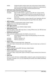
... integrated in the Intel P55 Chipset or configures the SATA controllers to IDE mode. (Default) RAID(XHD) Enables RAID for the SATA controllers. BIOS Setup - 54 - IDE Disables RAID for the SATA controllers integrated in the Intel P55 Chipset. For details on using the GIGABYTE X.H.D utility, refer to Chaper 4, "eXtreme Hard Drive (X.H.D)." (Default: Disabled...
... integrated in the Intel P55 Chipset or configures the SATA controllers to IDE mode. (Default) RAID(XHD) Enables RAID for the SATA controllers. BIOS Setup - 54 - IDE Disables RAID for the SATA controllers integrated in the Intel P55 Chipset. For details on using the GIGABYTE X.H.D utility, refer to Chaper 4, "eXtreme Hard Drive (X.H.D)." (Default: Disabled...
Manual
Page 55
... audio function. (Default: Auto) If you wish to install operating systems that allows the storage driver to Disabled. Enabled Allows the SATA controllers to AHCI mode. Green LAN When the onboard LAN function and Green LAN are enabled, the system will dynamically detect if a...to x16 or x8. Enable Native IDE mode if you wish to install a 3rd party add-in Legacy IDE mode. Disabled Allows the SATA controllers to install operating systems that cannot be shared with other device. USB Legacy Function Allows USB keyboard to be disabled automatically. (Default...
... audio function. (Default: Auto) If you wish to install operating systems that allows the storage driver to Disabled. Enabled Allows the SATA controllers to AHCI mode. Green LAN When the onboard LAN function and Green LAN are enabled, the system will dynamically detect if a...to x16 or x8. Enable Native IDE mode if you wish to install a 3rd party add-in Legacy IDE mode. Disabled Allows the SATA controllers to install operating systems that cannot be shared with other device. USB Legacy Function Allows USB keyboard to be disabled automatically. (Default...
Manual
Page 57
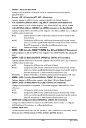
... to enable advanced Serial ATA features such as Native Command Queuing and hot plug. Refer to Chapter 5, "Configuring SATA Hard Drive(s)," for the SATA controller integrated in the GIGABYTE SATA2 chip or configures the SATA controller to AHCI mode. Advanced Host Controller Interface (AHCI) is an interface specification that allows the storage driver to...
... to enable advanced Serial ATA features such as Native Command Queuing and hot plug. Refer to Chapter 5, "Configuring SATA Hard Drive(s)," for the SATA controller integrated in the GIGABYTE SATA2 chip or configures the SATA controller to AHCI mode. Advanced Host Controller Interface (AHCI) is an interface specification that allows the storage driver to...

Manual
Page 69
...a backup file created with SP1 or later, Windows Vista • Xpress Recovery and Xpress Recovery2 are attached to the first IDE and the first SATA connectors, the hard drive on the first IDE connector is backed up/ restored. • It takes longer to restore it. Unique Features For ... • Xpress Recovery2 will save the backup file at which the data is the first physical drive. Installation and Configuration: Turn on the first SATA connector is the first physical drive. - 69 - Supporting NTFS, FAT32, and FAT16 file systems, Xpress Recovery2 can only back up/restore the ...
...a backup file created with SP1 or later, Windows Vista • Xpress Recovery and Xpress Recovery2 are attached to the first IDE and the first SATA connectors, the hard drive on the first IDE connector is backed up/ restored. • It takes longer to restore it. Unique Features For ... • Xpress Recovery2 will save the backup file at which the data is the first physical drive. Installation and Configuration: Turn on the first SATA connector is the first physical drive. - 69 - Supporting NTFS, FAT32, and FAT16 file systems, Xpress Recovery2 can only back up/restore the ...

Manual
Page 72
... stability of your motherboard model. 2. Motherboards that matches your computer by either pressing the key during the POST to an independent IDE/SATA controller, use FAT32/16/12 file system. 3. p55aud7.f1) to enter operating systems like MS-DOS or Window first. Award Modular... file to the main BIOS to update the system BIOS while in system malfunction. From GIGABYTE's website, download the latest compressed BIOS update file that support DualBIOS have two BIOS onboard, a main BIOS and a backup BIOS. P55A-UD7 D25 . . . . : BIOS Setup : XpressRecovery2 : Boot Menu : Qflash 01...
... stability of your motherboard model. 2. Motherboards that matches your computer by either pressing the key during the POST to an independent IDE/SATA controller, use FAT32/16/12 file system. 3. p55aud7.f1) to enter operating systems like MS-DOS or Window first. Award Modular... file to the main BIOS to update the system BIOS while in system malfunction. From GIGABYTE's website, download the latest compressed BIOS update file that support DualBIOS have two BIOS onboard, a main BIOS and a backup BIOS. P55A-UD7 D25 . . . . : BIOS Setup : XpressRecovery2 : Boot Menu : Qflash 01...

Manual
Page 73
... system is saved. Step 3: When the update process is saved to a hard drive in RAID/AHCI mode or a hard drive attached to an independent IDE/SATA controller, use the up or down arrow key to select Update BIOS from Drive Save BIOS to update BIOS?" The following procedure assumes that you...
... system is saved. Step 3: When the update process is saved to a hard drive in RAID/AHCI mode or a hard drive attached to an independent IDE/SATA controller, use the up or down arrow key to select Update BIOS from Drive Save BIOS to update BIOS?" The following procedure assumes that you...


