Manual
Page 4
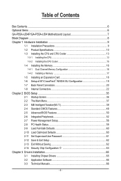
Table of Contents Box Contents...6 Optional Items...6 GA-P55A-UD4P/GA-P55A-UD4 Motherboard Layout 7 Block Diagram...8 Chapter 1 Hardware Installation 9 1-1 Installation Precautions 9 1-2 Product Specifications 10 1-3 Installing the CPU and CPU Cooler 13 ... the Memory 16 1-4-1 Dual Channel Memory Configuration 16 1-4-2 Installing a Memory 17 1-5 Installing an Expansion Card 18 1-6 Setup of ATI CrossFireX™/NVIDIA SLI Configuration 19 1-7 Back Panel Connectors 20 1-8 Internal Connectors 22 Chapter 2 BIOS Setup 35 2-1 Startup Screen 36 2-2 The Main Menu 37 2-3 MB Intelligent...
Table of Contents Box Contents...6 Optional Items...6 GA-P55A-UD4P/GA-P55A-UD4 Motherboard Layout 7 Block Diagram...8 Chapter 1 Hardware Installation 9 1-1 Installation Precautions 9 1-2 Product Specifications 10 1-3 Installing the CPU and CPU Cooler 13 ... the Memory 16 1-4-1 Dual Channel Memory Configuration 16 1-4-2 Installing a Memory 17 1-5 Installing an Expansion Card 18 1-6 Setup of ATI CrossFireX™/NVIDIA SLI Configuration 19 1-7 Back Panel Connectors 20 1-8 Internal Connectors 22 Chapter 2 BIOS Setup 35 2-1 Startup Screen 36 2-2 The Main Menu 37 2-3 MB Intelligent...
Manual
Page 6
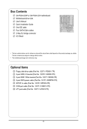
... port cable (Part No. 12CF1-1CM001-3*R) LPT port cable (Part No. 12CF1-1LP001-0*R) - 6 - Box Contents GA-P55A-UD4P or GA-P55A-UD4 motherboard Motherboard driver disk User's Manual Quick Installation Guide One IDE cable Four SATA 3Gb/s cables 2-Way SLI bridge connector I/O Shield • The box contents above are subject to change without notice. • The...
... port cable (Part No. 12CF1-1CM001-3*R) LPT port cable (Part No. 12CF1-1LP001-0*R) - 6 - Box Contents GA-P55A-UD4P or GA-P55A-UD4 motherboard Motherboard driver disk User's Manual Quick Installation Guide One IDE cable Four SATA 3Gb/s cables 2-Way SLI bridge connector I/O Shield • The box contents above are subject to change without notice. • The...
Manual
Page 10
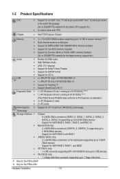
...; Support for Extreme Memory Profile (XMP) memory modules (Go to GIGABYTE's website for the latest memory support list.) Audio Realtek ALC889...SLI technology Technology Storage Interface Chipset: - 6 x SATA 3Gb/s connectors (SATA2_0, SATA2_1, SATA2_2, SATA2_3, SATA2_4, SATA2_5) supporting up to 2 SATA 6Gb/s devices - k Only for SATA RAID 0, RAID 1, RAID 5, and RAID 10 Marvell 9128 chip: - 2 x SATA 6Gb/s connectors (GSATA3_6, GSATA3_7) supporting up to 6 SATA 3Gb/s devices - Support for GA-P55A-UD4...
...; Support for Extreme Memory Profile (XMP) memory modules (Go to GIGABYTE's website for the latest memory support list.) Audio Realtek ALC889...SLI technology Technology Storage Interface Chipset: - 6 x SATA 3Gb/s connectors (SATA2_0, SATA2_1, SATA2_2, SATA2_3, SATA2_4, SATA2_5) supporting up to 2 SATA 6Gb/s devices - k Only for SATA RAID 0, RAID 1, RAID 5, and RAID 10 Marvell 9128 chip: - 2 x SATA 6Gb/s connectors (GSATA3_6, GSATA3_7) supporting up to 6 SATA 3Gb/s devices - Support for GA-P55A-UD4...
Manual
Page 19
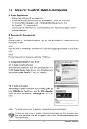
...x16 slots and correct driver - Step 3: Plug the display cable into the graphics card on top of your graphics cards. A CrossFireX/SLI-supported motherboard with your graphics cards for the power requirement) B. Connecting the Graphics Cards Step 1: Observe the steps in the operating system... system, go to the ATI Catalyst Control Center. To Enable CrossFireX Function After installing the graphics card driver in the CrossFireX/SLI gold edge connectors on the PCIEX16 slot. Refer to the CrossFireX menu and ensure the Enable CrossFireX™ check box is selected...
...x16 slots and correct driver - Step 3: Plug the display cable into the graphics card on top of your graphics cards. A CrossFireX/SLI-supported motherboard with your graphics cards for the power requirement) B. Connecting the Graphics Cards Step 1: Observe the steps in the operating system... system, go to the ATI Catalyst Control Center. To Enable CrossFireX Function After installing the graphics card driver in the CrossFireX/SLI gold edge connectors on the PCIEX16 slot. Refer to the CrossFireX menu and ensure the Enable CrossFireX™ check box is selected...


