
Manual
Page 1
...Installing the SATA RAID/AHCI Driver and Operating System." ) Step 3: Install the motherboard drivers and the X.H.D utiltiy After installing the operating system, insert the motherboard driver disk. Using GIGABYTE eXtreme Hard Drive (X.H.D) Instructions:(Note 2) Before launching X.H.D, make sure the newly... utility. (Note 1) The X.H.D utility only supports the SATA controllers integrated in the array. ) 1. B. eXtreme Hard Drive (X.H.D) With GIGABYTE eXtreme Hard Drive (X.H.D)(Note 1), users can click the Xpress Install All button to automatically install all of data. (Note 3) If you ...
...Installing the SATA RAID/AHCI Driver and Operating System." ) Step 3: Install the motherboard drivers and the X.H.D utiltiy After installing the operating system, insert the motherboard driver disk. Using GIGABYTE eXtreme Hard Drive (X.H.D) Instructions:(Note 2) Before launching X.H.D, make sure the newly... utility. (Note 1) The X.H.D utility only supports the SATA controllers integrated in the array. ) 1. B. eXtreme Hard Drive (X.H.D) With GIGABYTE eXtreme Hard Drive (X.H.D)(Note 1), users can click the Xpress Install All button to automatically install all of data. (Note 3) If you ...

Manual
Page 1
GA-P55A-UD3 LGA1156 socket motherboard for Intel® Core™ i7 processor family/ Intel® Core™ i5 processor family User's Manual Rev. 1002 12ME-P55AUD3-1002R
GA-P55A-UD3 LGA1156 socket motherboard for Intel® Core™ i7 processor family/ Intel® Core™ i5 processor family User's Manual Rev. 1002 12ME-P55AUD3-1002R
Manual
Page 2
Motherboard GA-P55A-UD3 Oct. 19, 2009 Motherboard GA-P55A-UD3 Oct. 19, 2009
Motherboard GA-P55A-UD3 Oct. 19, 2009 Motherboard GA-P55A-UD3 Oct. 19, 2009
Manual
Page 3
... to assist in any form or by any means without prior notice. Check your motherboard looks like this: "REV: X.X." Documentation Classifications In order to use of the motherboard is protected by GIGABYTE without GIGABYTE's prior written permission. For example, "REV: 1.0" means the revision of this..., or when looking for technical information. For product-related information, check on our website at: http://www.gigabyte.com.tw Identifying Your Motherboard Revision The revision number on our website. Example: Disclaimer Information in this manual are legally registered to the...
... to assist in any form or by any means without prior notice. Check your motherboard looks like this: "REV: X.X." Documentation Classifications In order to use of the motherboard is protected by GIGABYTE without GIGABYTE's prior written permission. For example, "REV: 1.0" means the revision of this..., or when looking for technical information. For product-related information, check on our website at: http://www.gigabyte.com.tw Identifying Your Motherboard Revision The revision number on our website. Example: Disclaimer Information in this manual are legally registered to the...
Manual
Page 4
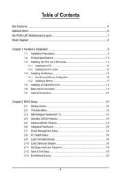
Table of Contents Box Contents...6 Optional Items...6 GA-P55A-UD3 Motherboard Layout 7 Block Diagram...8 Chapter 1 Hardware Installation 9 1-1 Installation Precautions 9 1-2 Product Specifications 10 1-3 Installing the CPU and CPU Cooler 13 1-3-1 Installing the CPU 13 1-3-2 Installing the CPU ...
Table of Contents Box Contents...6 Optional Items...6 GA-P55A-UD3 Motherboard Layout 7 Block Diagram...8 Chapter 1 Hardware Installation 9 1-1 Installation Precautions 9 1-2 Product Specifications 10 1-3 Installing the CPU and CPU Cooler 13 1-3-1 Installing the CPU 13 1-3-2 Installing the CPU ...

Manual
Page 6
.... 12CF1-2SERPW-0*R) S/PDIF In cable (Part No. 12CR1-1SPDIN-0*R) COM port cable (Part No. 12CF1-1CM001-3*R) LPT port cable (Part No. 12CF1-1LP001-0*R) - 6 - Box Contents GA-P55A-UD3 motherboard Motherboard driver disk User's Manual Quick Installation Guide One IDE cable Two SATA 3Gb/s cables I/O Shield • The box contents above are subject to change without...
.... 12CF1-2SERPW-0*R) S/PDIF In cable (Part No. 12CR1-1SPDIN-0*R) COM port cable (Part No. 12CF1-1CM001-3*R) LPT port cable (Part No. 12CF1-1LP001-0*R) - 6 - Box Contents GA-P55A-UD3 motherboard Motherboard driver disk User's Manual Quick Installation Guide One IDE cable Two SATA 3Gb/s cables I/O Shield • The box contents above are subject to change without...
Manual
Page 7
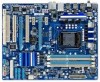
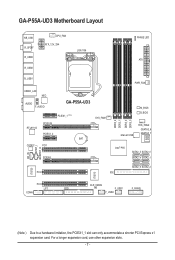
GA-P55A-UD3 Motherboard Layout KB_USB R_SPDIF R_USB3 R_USB2 CPU_FAN ATX_12V_2X4 LGA1156 PHASE LED ATX R_USB1 USB30_LAN NEC AUDIO F_AUDIO GA-P55A-UD3 PCIEX1_1 (Note) RTL8111D PCIEX16 PCIEX1_2 BAT CODEC PCI1 SYS_FAN1 CD_IN SPDIF_I SPDIF_O PCIEX4 DDR3_2 DDR3_1 DDR3_4 DDR3_3 PWR_FAN M_BIOS B_BIOS Marvell 9128 SYS_FAN2 GSATA3_6 GSATA3_7 ...
GA-P55A-UD3 Motherboard Layout KB_USB R_SPDIF R_USB3 R_USB2 CPU_FAN ATX_12V_2X4 LGA1156 PHASE LED ATX R_USB1 USB30_LAN NEC AUDIO F_AUDIO GA-P55A-UD3 PCIEX1_1 (Note) RTL8111D PCIEX16 PCIEX1_2 BAT CODEC PCI1 SYS_FAN1 CD_IN SPDIF_I SPDIF_O PCIEX4 DDR3_2 DDR3_1 DDR3_4 DDR3_3 PWR_FAN M_BIOS B_BIOS Marvell 9128 SYS_FAN2 GSATA3_6 GSATA3_7 ...

Manual
Page 9
... - 9 - ponents such as a result of your dealer. Hardware Installation If you are connected tightly and securely. • When handling the motherboard, avoid touching any installation steps or have it on top of an antistatic pad or within the computer casing. • Do not place the computer...an ESD wrist strap, keep your hands dry and first touch a metal object to eliminate static electricity. • Prior to installing the motherboard, please have a problem related to the local voltage standard. • Before using the product, please verify that all cables and power ...
... - 9 - ponents such as a result of your dealer. Hardware Installation If you are connected tightly and securely. • When handling the motherboard, avoid touching any installation steps or have it on top of an antistatic pad or within the computer casing. • Do not place the computer...an ESD wrist strap, keep your hands dry and first touch a metal object to eliminate static electricity. • Prior to installing the motherboard, please have a problem related to the local voltage standard. • Before using the product, please verify that all cables and power ...
Manual
Page 12
... CPU/system fan speed control function is supported will depend on the CPU/system cooler you install. (Note 6) Available functions in EasyTune may differ by motherboard model. Hardware Installation - 12 -
... CPU/system fan speed control function is supported will depend on the CPU/system cooler you install. (Note 6) Available functions in EasyTune may differ by motherboard model. Hardware Installation - 12 -

Manual
Page 13
Locate the alignment keys on the motherboard CPU socket and the notches on the CPU - 13 - 1-3 Installing the CPU and CPU Cooler Read the following guidelines before installing the CPU to your ... the computer and unplug the power cord from the power outlet before you begin to install the CPU: • Make sure that the motherboard supports the CPU. (Go to GIGABYTE's website for the latest CPU support list.) • Always turn on the computer if the CPU cooler is not recommended that the...
Locate the alignment keys on the motherboard CPU socket and the notches on the CPU - 13 - 1-3 Installing the CPU and CPU Cooler Read the following guidelines before installing the CPU to your ... the computer and unplug the power cord from the power outlet before you begin to install the CPU: • Make sure that the motherboard supports the CPU. (Go to GIGABYTE's website for the latest CPU support list.) • Always turn on the computer if the CPU cooler is not recommended that the...

Manual
Page 14
... CPU is properly inserted, use one hand to hold the socket lever and use your finger. Step 5: Push the CPU socket lever back into the motherboard CPU socket. Step 1: Gently press the CPU socket lever handle down on the rear grip of the CPU socket (or you may align the CPU...
... CPU is properly inserted, use one hand to hold the socket lever and use your finger. Step 5: Push the CPU socket lever back into the motherboard CPU socket. Step 1: Gently press the CPU socket lever handle down on the rear grip of the CPU socket (or you may align the CPU...

Manual
Page 15
...push pin. Step 6: Finally, attach the power connector of the installed CPU. Step 4: You should hear a "click" when pushing down on the motherboard. Use extreme care when removing the CPU cooler because the thermal grease/tape between the CPU cooler and CPU may damage the CPU. - 15 - ...the CPU cooler may adhere to the CPU. 1-3-2 Installing the CPU Cooler Follow the steps below to correctly install the CPU cooler on the motherboard. (The following procedure uses Intel® boxed cooler as the picture above shows, the installation is complete. Direction of the Arrow Sign ...
...push pin. Step 6: Finally, attach the power connector of the installed CPU. Step 4: You should hear a "click" when pushing down on the motherboard. Use extreme care when removing the CPU cooler because the thermal grease/tape between the CPU cooler and CPU may damage the CPU. - 15 - ...the CPU cooler may adhere to the CPU. 1-3-2 Installing the CPU Cooler Follow the steps below to correctly install the CPU cooler on the motherboard. (The following procedure uses Intel® boxed cooler as the picture above shows, the installation is complete. Direction of the Arrow Sign ...

Manual
Page 16
... only one direction. It is installed, be sure to insert the memory, switch the direction. 1-4-1 Dual Channel Memory Configuration This motherboard provides four DDR3 memory sockets and supports Dual Channel Technology. After the memory is installed. 2. Enabling Dual Channel memory mode will ... DDR3_3 sockets. If you are divided into two channels and each channel has two memory sockets as following guidelines before you begin to GIGABYTE's website for optimum performance. 1-4 Installing the Memory Read the following : Channel 0: DDR3_1, DDR3_2 Channel 1: DDR3_3, DDR3_4 Dual Channel...
... only one direction. It is installed, be sure to insert the memory, switch the direction. 1-4-1 Dual Channel Memory Configuration This motherboard provides four DDR3 memory sockets and supports Dual Channel Technology. After the memory is installed. 2. Enabling Dual Channel memory mode will ... DDR3_3 sockets. If you are divided into two channels and each channel has two memory sockets as following guidelines before you begin to GIGABYTE's website for optimum performance. 1-4 Installing the Memory Read the following : Channel 0: DDR3_1, DDR3_2 Channel 1: DDR3_3, DDR3_4 Dual Channel...

Manual
Page 17
... power cord from the power outlet to prevent damage to correctly install your fingers on the top edge of the memory, push down on this motherboard.
... power cord from the power outlet to prevent damage to correctly install your fingers on the top edge of the memory, push down on this motherboard.

Manual
Page 18
Remove the metal slot cover from the power outlet before you begin to install an expansion card: • Make sure the motherboard supports the expansion card. 1-5 Installing an Expansion Card Read the following guidelines before installing an expansion card to prevent hardware damage. Secure the card's metal ...
Remove the metal slot cover from the power outlet before you begin to install an expansion card: • Make sure the motherboard supports the expansion card. 1-5 Installing an Expansion Card Read the following guidelines before installing an expansion card to prevent hardware damage. Secure the card's metal ...

Manual
Page 19
... and etc. • When removing the cable connected to a back panel connector, first remove the cable from your device and then remove it from the motherboard. • When removing the cable, pull it side to side to an external audio system that your audio system provides an optical digital audio in...
... and etc. • When removing the cable connected to a back panel connector, first remove the cable from your device and then remove it from the motherboard. • When removing the cable, pull it side to side to an external audio system that your audio system provides an optical digital audio in...
Manual
Page 21
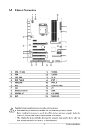
...) CD_IN 14) SPDIF_I 15) SPDIF_O 16) F_USB1/F_USB2 17) LPT 18) COMA 19) CLR_CMOS 20) PHASE LED Read the following guidelines before turning on the motherboard. - 21 -
...) CD_IN 14) SPDIF_I 15) SPDIF_O 16) F_USB1/F_USB2 17) LPT 18) COMA 19) CLR_CMOS 20) PHASE LED Read the following guidelines before turning on the motherboard. - 21 -

Manual
Page 22
...providing a 2x2 12V and a 2x10 power connector. 8 4 5 1 ATX_12V_2X4 ATX_12V_2X4: Pin No. If a power supply is turned off and all the components on the motherboard. Definition 1 GND (Only for 2x4-pin 12V) 2 GND (Only for 2x4-pin 12V) 3 GND 4 GND 5 +12V (Only for 2x4-pin 12V) 6 +...supply providing a 2x4 12V and a 2x12 power connector, remove the protective covers from the 12V power connector and the main power connector on the motherboard. The power connector possesses a foolproof design. 1/2) ATX_12V_2X4/ATX (2x4 12V Power Connector and 2x12 Main Power Connector) With the use of a...
...providing a 2x2 12V and a 2x10 power connector. 8 4 5 1 ATX_12V_2X4 ATX_12V_2X4: Pin No. If a power supply is turned off and all the components on the motherboard. Definition 1 GND (Only for 2x4-pin 12V) 2 GND (Only for 2x4-pin 12V) 3 GND 4 GND 5 +12V (Only for 2x4-pin 12V) 6 +...supply providing a 2x4 12V and a 2x12 power connector, remove the protective covers from the 12V power connector and the main power connector on the motherboard. The power connector possesses a foolproof design. 1/2) ATX_12V_2X4/ATX (2x4 12V Power Connector and 2x12 Main Power Connector) With the use of a...

Manual
Page 23
3/4/5) CPU_FAN/SYS_FAN1/SYS_FAN2/PWR_FAN (Fan Headers) The motherboard has a 4-pin CPU fan header (CPU_FAN), a 4-pin (SYS_FAN2) and two 3-pin (SYS_ FAN1) system fan headers, and a 3-pin power fan header (PWR_FAN). mended that a system ... : 360 KB, 720 KB, 1.2 MB, 1.44 MB, and 2.88 MB. Hardware Installation Definition 1 GND 1 2 +12V / Speed Control CPU_FAN 3 Sense 4 Speed Control SYS_FAN2: Pin No. The motherboard supports CPU fan speed control, which requires the use of the connector and the floppy disk drive cable. The types of different color. CPU_FAN: Pin...
3/4/5) CPU_FAN/SYS_FAN1/SYS_FAN2/PWR_FAN (Fan Headers) The motherboard has a 4-pin CPU fan header (CPU_FAN), a 4-pin (SYS_FAN2) and two 3-pin (SYS_ FAN1) system fan headers, and a 3-pin power fan header (PWR_FAN). mended that a system ... : 360 KB, 720 KB, 1.2 MB, 1.44 MB, and 2.88 MB. Hardware Installation Definition 1 GND 1 2 +12V / Speed Control CPU_FAN 3 Sense 4 Speed Control SYS_FAN2: Pin No. The motherboard supports CPU fan speed control, which requires the use of the connector and the floppy disk drive cable. The types of different color. CPU_FAN: Pin...

Manual
Page 27
... assignments of the module connector match the pin assignments of a single plug. Incorrect connection between the module connector and the motherboard header will be present on each wire instead of the motherboard header. If your chassis front panel audio module to work or even damage it. Definition 1 2 1 MIC2_L 1 MIC 2 GND 2 GND 9 10...
... assignments of the module connector match the pin assignments of a single plug. Incorrect connection between the module connector and the motherboard header will be present on each wire instead of the motherboard header. If your chassis front panel audio module to work or even damage it. Definition 1 2 1 MIC2_L 1 MIC 2 GND 2 GND 9 10...


