
Manual
Page 1
... to exit the X.H.D utility. (Note 1) The X.H.D utility only supports the SATA controllers integrated in the array. ) 1. eXtreme Hard Drive (X.H.D) With GIGABYTE eXtreme Hard Drive (X.H.D)(Note 1), users can quickly configure a RAIDready system for RAID 0 when a new SATA drive is greater than the RAID-ready system...automatically install all of data. (Note 3) If you manually build a non-RAID 0 array, you run the X.H.D utility, back up all motherboard drivers, including the X.H.D utility. B. The following procedure details the steps to set up a RAID array: (Note 3): Click Manual to ...
... to exit the X.H.D utility. (Note 1) The X.H.D utility only supports the SATA controllers integrated in the array. ) 1. eXtreme Hard Drive (X.H.D) With GIGABYTE eXtreme Hard Drive (X.H.D)(Note 1), users can quickly configure a RAIDready system for RAID 0 when a new SATA drive is greater than the RAID-ready system...automatically install all of data. (Note 3) If you manually build a non-RAID 0 array, you run the X.H.D utility, back up all motherboard drivers, including the X.H.D utility. B. The following procedure details the steps to set up a RAID array: (Note 3): Click Manual to ...
Manual
Page 1
GA-P55-UD3L-TPM/ GA-P55-UD3L/ GA-P55-US3L LGA1156 socket motherboard for Intel® Core™ i7 processor family/ Intel® Core™ i5 processor family User's Manual Rev. 1002 12ME-P55UD3L-1002R
GA-P55-UD3L-TPM/ GA-P55-UD3L/ GA-P55-US3L LGA1156 socket motherboard for Intel® Core™ i7 processor family/ Intel® Core™ i5 processor family User's Manual Rev. 1002 12ME-P55UD3L-1002R

Manual
Page 3
Motherboard GA-P55-UD3L-TPM Oct. 5, 2009 Motherboard GA-P55-UD3L-TPM Oct. 5, 2009
Motherboard GA-P55-UD3L-TPM Oct. 5, 2009 Motherboard GA-P55-UD3L-TPM Oct. 5, 2009
Manual
Page 4
...Support&Downloads\Motherboard\Technology Guide page on your motherboard revision before updating motherboard BIOS, drivers, or when looking for technical information. Documentation Classifications In order to use of GIGABYTE. Check your motherboard looks like this product, GIGABYTE provides the... following types of documentations: For quick set-up of the motherboard is the property of this : "REV: X.X." For ...
...Support&Downloads\Motherboard\Technology Guide page on your motherboard revision before updating motherboard BIOS, drivers, or when looking for technical information. Documentation Classifications In order to use of GIGABYTE. Check your motherboard looks like this product, GIGABYTE provides the... following types of documentations: For quick set-up of the motherboard is the property of this : "REV: X.X." For ...
Manual
Page 5
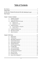
Table of Contents Box Contents...7 Optional Items...7 GA-P55-UD3L-TPM/GA-P55-UD3L/GA-P55-US3L Motherboard Layout 8 Block Diagram...9 Chapter 1 Hardware Installation 11 1-1 Installation Precautions 11 1-2 Product Specifications 12 1-3 Installing the CPU and CPU Cooler 15 1-3-1 Installing the CPU 15 1-3-2 Installing ...
Table of Contents Box Contents...7 Optional Items...7 GA-P55-UD3L-TPM/GA-P55-UD3L/GA-P55-US3L Motherboard Layout 8 Block Diagram...9 Chapter 1 Hardware Installation 11 1-1 Installation Precautions 11 1-2 Product Specifications 12 1-3 Installing the CPU and CPU Cooler 15 1-3-1 Installing the CPU 15 1-3-2 Installing ...
Manual
Page 7
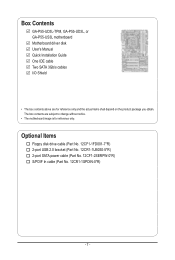
... USB 2.0 bracket (Part No. 12CR1-1UB030-5*R) 2-port SATA power cable (Part No. 12CF1-2SERPW-0*R) S/PDIF In cable (Part No. 12CR1-1SPDIN-0*R) - 7 - Box Contents GA-P55-UD3L-TPM, GA-P55-UD3L, or GA-P55-US3L motherboard Motherboard driver disk User's Manual Quick Installation Guide One IDE cable Two SATA 3Gb/s cables I/O Shield • The box contents above are subject to...
... USB 2.0 bracket (Part No. 12CR1-1UB030-5*R) 2-port SATA power cable (Part No. 12CF1-2SERPW-0*R) S/PDIF In cable (Part No. 12CR1-1SPDIN-0*R) - 7 - Box Contents GA-P55-UD3L-TPM, GA-P55-UD3L, or GA-P55-US3L motherboard Motherboard driver disk User's Manual Quick Installation Guide One IDE cable Two SATA 3Gb/s cables I/O Shield • The box contents above are subject to...
Manual
Page 8
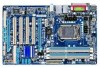
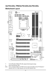
...GA-P55-UD3L-TPM/GA-P55-UD3L/GA-P55-US3L Motherboard Layout KB_USB ATX_12V GA-P55-UD3L-TPM/ GA-P55-UD3L / GA-P55-US3L PHASE LED LGA1156 PWR_FAN COAXIAL COMA LPT R_USB ATX USB_LAN AUDIO F_AUDIO SYS_FAN1 PCIEX1 (Note) BAT CPU_FAN DDR3_2 DDR3_1 DDR3_4 DDR3_3 RTL8111D CODEC SPDIF_O CD_IN TPM ICj SPDIF_I PCIEX16 PCI1 PCI2 PCI3 PCI4 SYS_FAN2 Intel® P55... GSATA2_0 CLR_CMOS GIGABYTE SATA2 GSATA2_1 F_PANEL "*" j (Note) The GA-P55-UD3L-TPM/GA-P55-UD3L adopts All-Solid Capacitor design. For a longer expansion card, use other expansion slots. - 8 - Only for GA-P55-UD3L-TPM....
...GA-P55-UD3L-TPM/GA-P55-UD3L/GA-P55-US3L Motherboard Layout KB_USB ATX_12V GA-P55-UD3L-TPM/ GA-P55-UD3L / GA-P55-US3L PHASE LED LGA1156 PWR_FAN COAXIAL COMA LPT R_USB ATX USB_LAN AUDIO F_AUDIO SYS_FAN1 PCIEX1 (Note) BAT CPU_FAN DDR3_2 DDR3_1 DDR3_4 DDR3_3 RTL8111D CODEC SPDIF_O CD_IN TPM ICj SPDIF_I PCIEX16 PCI1 PCI2 PCI3 PCI4 SYS_FAN2 Intel® P55... GSATA2_0 CLR_CMOS GIGABYTE SATA2 GSATA2_1 F_PANEL "*" j (Note) The GA-P55-UD3L-TPM/GA-P55-UD3L adopts All-Solid Capacitor design. For a longer expansion card, use other expansion slots. - 8 - Only for GA-P55-UD3L-TPM....
Manual
Page 11
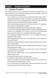
..., please verify that all cables and power connectors of your dealer. Hardware Installation Chapter 1 Hardware Installation 1-1 Installation Precautions The motherboard contains numerous delicate electronic circuits and components which can lead to damage to system components as well as physical harm to the ... electrostatic shielding container. • Before unplugging the power supply cable from the power outlet before installing or removing the motherboard or other hardware components. • When connecting hardware components to the internal connectors on the computer power during the...
..., please verify that all cables and power connectors of your dealer. Hardware Installation Chapter 1 Hardware Installation 1-1 Installation Precautions The motherboard contains numerous delicate electronic circuits and components which can lead to damage to system components as well as physical harm to the ... electrostatic shielding container. • Before unplugging the power supply cable from the power outlet before installing or removing the motherboard or other hardware components. • When connecting hardware components to the internal connectors on the computer power during the...
Manual
Page 14
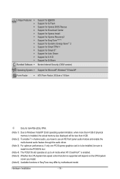
... Internet Security (OEM version) Operating System w Support for Microsoft® Windows® 7/Vista/XP Form Factor w ATX Form Factor; 30.5cm x 19.0cm j Only for GA-P55-UD3L-TPM. (Note 1) Due to Windows Vista/XP 32-bit operating system limitation, when more than 4 GB of physical memory is installed, the actual memory... CPU/system fan speed control function is supported will depend on the CPU/system cooler you install. (Note 6) Available functions in EasyTune may differ by motherboard model.
... Internet Security (OEM version) Operating System w Support for Microsoft® Windows® 7/Vista/XP Form Factor w ATX Form Factor; 30.5cm x 19.0cm j Only for GA-P55-UD3L-TPM. (Note 1) Due to Windows Vista/XP 32-bit operating system limitation, when more than 4 GB of physical memory is installed, the actual memory... CPU/system fan speed control function is supported will depend on the CPU/system cooler you install. (Note 6) Available functions in EasyTune may differ by motherboard model.
Manual
Page 15
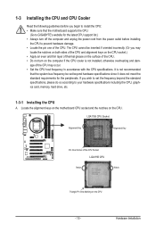
...CPU host frequency in accordance with the CPU specifications. It is not installed, otherwise overheating and dam- Locate the alignment keys on the motherboard CPU socket and the notches on the CPU - 15 - Hardware Installation If you wish to set beyond the standard specifications, please do ...so according to GIGABYTE's website for the latest CPU support list.) • Always turn on the computer if the CPU cooler is not recommended that the motherboard supports the CPU. (Go to your hardware specifications including the CPU, ...
...CPU host frequency in accordance with the CPU specifications. It is not installed, otherwise overheating and dam- Locate the alignment keys on the motherboard CPU socket and the notches on the CPU - 15 - Hardware Installation If you wish to set beyond the standard specifications, please do ...so according to GIGABYTE's website for the latest CPU support list.) • Always turn on the computer if the CPU cooler is not recommended that the motherboard supports the CPU. (Go to your hardware specifications including the CPU, ...
Manual
Page 16
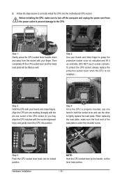
... socket contacts. Step 5: Push the CPU socket lever back into position. When replacing the load plate, make sure to correctly install the CPU into the motherboard CPU socket. Step 2: Use your thumb and index finger to lightly replace the load plate. Align the CPU pin one marking (triangle) with the pin...
... socket contacts. Step 5: Push the CPU socket lever back into position. When replacing the load plate, make sure to correctly install the CPU into the motherboard CPU socket. Step 2: Use your thumb and index finger to lightly replace the load plate. Align the CPU pin one marking (triangle) with the pin...
Manual
Page 17
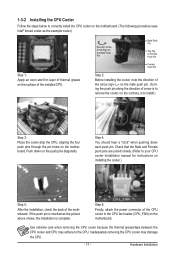
...Step 3: Place the cooler atop the CPU, aligning the four push pins through the pin holes on the motherboard. Hardware Installation Step 6: Finally, attach the power connector of the motherboard. Direction of the Arrow Sign on the Male Push Pin Male Push Pin The Top of Female Push Pin ..." when pushing down on the push pins diagonally. 1-3-2 Installing the CPU Cooler Follow the steps below to correctly install the CPU cooler on the motherboard. (The following procedure uses Intel® boxed cooler as the picture above shows, the installation is complete. If the push pin is inserted as...
...Step 3: Place the cooler atop the CPU, aligning the four push pins through the pin holes on the motherboard. Hardware Installation Step 6: Finally, attach the power connector of the motherboard. Direction of the Arrow Sign on the Male Push Pin Male Push Pin The Top of Female Push Pin ..." when pushing down on the push pins diagonally. 1-3-2 Installing the CPU Cooler Follow the steps below to correctly install the CPU cooler on the motherboard. (The following procedure uses Intel® boxed cooler as the picture above shows, the installation is complete. If the push pin is inserted as...
Manual
Page 18
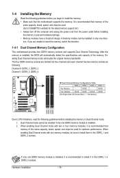
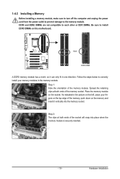
If you begin to GIGABYTE's website for optimum performance. DS/SS - - When enabling Dual Channel mode with ...guidelines before installing the memory to insert the memory, switch the direction. 1-4-1 Dual Channel Memory Configuration This motherboard provides four DDR3 memory sockets and supports Dual Channel Technology. After the memory is recommended that memory of ...the memory. Dual Channel mode cannot be used . (Go to install the memory: • Make sure that the motherboard supports the memory. Hardware Installation - 18 - DS/SS Four Modules DS/SS DS/SS DS/SS DS/SS (SS...
If you begin to GIGABYTE's website for optimum performance. DS/SS - - When enabling Dual Channel mode with ...guidelines before installing the memory to insert the memory, switch the direction. 1-4-1 Dual Channel Memory Configuration This motherboard provides four DDR3 memory sockets and supports Dual Channel Technology. After the memory is recommended that memory of ...the memory. Dual Channel mode cannot be used . (Go to install the memory: • Make sure that the motherboard supports the memory. Hardware Installation - 18 - DS/SS Four Modules DS/SS DS/SS DS/SS DS/SS (SS...
Manual
Page 19
..., make sure to turn off the computer and unplug the power cord from the power outlet to prevent damage to install DDR3 DIMMs on this motherboard. Step 2: The clips at both ends of the memory, push down on the socket.
..., make sure to turn off the computer and unplug the power cord from the power outlet to prevent damage to install DDR3 DIMMs on this motherboard. Step 2: The clips at both ends of the memory, push down on the socket.
Manual
Page 20
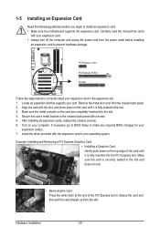
... on your card. 1-5 Installing an Expansion Card Read the following guidelines before installing an expansion card to install an expansion card: • Make sure the motherboard supports the expansion card. Carefully read the manual that supports your computer.
... on your card. 1-5 Installing an Expansion Card Read the following guidelines before installing an expansion card to install an expansion card: • Make sure the motherboard supports the expansion card. Carefully read the manual that supports your computer.
Manual
Page 21
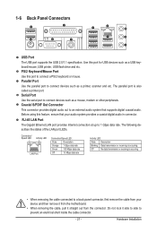
... Port The Gigabit Ethernet LAN port provides Internet connection at up to an external audio system that your device and then remove it from the motherboard. • When removing the cable, pull it side to side to prevent an electrical short inside the cable connector. - 21 - PS/2 Keyboard/Mouse Port Use...
... Port The Gigabit Ethernet LAN port provides Internet connection at up to an external audio system that your device and then remove it from the motherboard. • When removing the cable, pull it side to side to prevent an electrical short inside the cable connector. - 21 - PS/2 Keyboard/Mouse Port Use...
Manual
Page 23
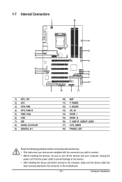
...) F_PANEL 12) F_AUDIO 13) CD_IN 14) SPDIF_I 15) SPDIF_O 16) F_USB1/F_USB2/F_USB3 17) CLR_CMOS 18) PHASE_LED Read the following guidelines before turning on the motherboard. - 23 - Unplug the power cord from the power outlet to prevent damage to the devices. • After installing the device and before connecting external devices...
...) F_PANEL 12) F_AUDIO 13) CD_IN 14) SPDIF_I 15) SPDIF_O 16) F_USB1/F_USB2/F_USB3 17) CLR_CMOS 18) PHASE_LED Read the following guidelines before turning on the motherboard. - 23 - Unplug the power cord from the power outlet to prevent damage to the devices. • After installing the device and before connecting external devices...
Manual
Page 24
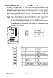
... power connector is not connected, the computer will not start. • To meet expansion requirements, it is turned off and all the components on the motherboard. When using a 2x10 power supply. 3 4 1 2 ATX_12V ATX_12V: Pin No. 1 2 3 4 Definition GND GND +12V +12V 12 24 1 13 ATX ATX: Pin No. 1 2 3 4 5 ...into pins under the protective cover when using a 2x12 power supply, remove the protective cover from the main power connector on the motherboard. Connect the power supply cable to the CPU. If a power supply is used (500W or greater). The 12V power connector ...
... power connector is not connected, the computer will not start. • To meet expansion requirements, it is turned off and all the components on the motherboard. When using a 2x10 power supply. 3 4 1 2 ATX_12V ATX_12V: Pin No. 1 2 3 4 Definition GND GND +12V +12V 12 24 1 13 ATX ATX: Pin No. 1 2 3 4 5 ...into pins under the protective cover when using a 2x12 power supply, remove the protective cover from the main power connector on the motherboard. Connect the power supply cable to the CPU. If a power supply is used (500W or greater). The 12V power connector ...
Manual
Page 25
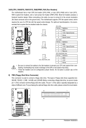
...MB, 1.44 MB, and 2.88 MB. Before connecting a floppy disk drive, be installed inside the chassis. 3/4/5) CPU_FAN/SYS_FAN1/SYS_FAN2/PWR_FAN (Fan Headers) The motherboard has a 4-pin CPU fan header (CPU_FAN), a 4-pin (SYS_FAN2) and a 3-pin (SYS_ FAN1) system fan headers, and a 3-pin power fan ... connector and the floppy disk drive cable. For optimum heat dissipation, it in damage to locate pin 1 of different color. The motherboard supports CPU fan speed control, which requires the use of floppy disk drives supported are not configuration jumper blocks. Definition 1 GND ...
...MB, 1.44 MB, and 2.88 MB. Before connecting a floppy disk drive, be installed inside the chassis. 3/4/5) CPU_FAN/SYS_FAN1/SYS_FAN2/PWR_FAN (Fan Headers) The motherboard has a 4-pin CPU fan header (CPU_FAN), a 4-pin (SYS_FAN2) and a 3-pin (SYS_ FAN1) system fan headers, and a 3-pin power fan ... connector and the floppy disk drive cable. For optimum heat dissipation, it in damage to locate pin 1 of different color. The motherboard supports CPU fan speed control, which requires the use of floppy disk drives supported are not configuration jumper blocks. Definition 1 GND ...
Manual
Page 29
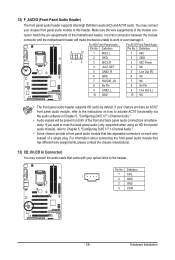
...GND 10 NC • The front panel audio header supports HD audio by default. Pin No. Incorrect connection between the module connector and the motherboard header will be present on each wire instead of a single plug. If your chassis front panel audio module to work or even damage it.... You may connect the audio cable that has separated connectors on both of the motherboard header. For information about connecting the front panel audio module that has different wire assignments, please contact the chassis manufacturer. 13) CD_IN ...
...GND 10 NC • The front panel audio header supports HD audio by default. Pin No. Incorrect connection between the module connector and the motherboard header will be present on each wire instead of a single plug. If your chassis front panel audio module to work or even damage it.... You may connect the audio cable that has separated connectors on both of the motherboard header. For information about connecting the front panel audio module that has different wire assignments, please contact the chassis manufacturer. 13) CD_IN ...


