
Manual
Page 1
... Hard Drive (X.H.D) With GIGABYTE eXtreme Hard Drive (X.H.D)(Note 1), users can quickly configure a RAIDready system for RAID 0. Step 2: Install the RAID driver and operating system The X.H.D utility supports Windows 7/Vista/XP. B. To automatically set up a RAID 0 array: Click Auto to automatically and quickly set eXtreme Hard Drive (X.H.D) under the Integrated Peripherals menu to Enabled to individually install the X.H.D utility later. All with which you can go to the Application Software screen to enable RAID for complex and time-consuming configurations...
... Hard Drive (X.H.D) With GIGABYTE eXtreme Hard Drive (X.H.D)(Note 1), users can quickly configure a RAIDready system for RAID 0. Step 2: Install the RAID driver and operating system The X.H.D utility supports Windows 7/Vista/XP. B. To automatically set up a RAID 0 array: Click Auto to automatically and quickly set eXtreme Hard Drive (X.H.D) under the Integrated Peripherals menu to Enabled to individually install the X.H.D utility later. All with which you can go to the Application Software screen to enable RAID for complex and time-consuming configurations...
Manual
Page 4
... motherboard looks like this manual are legally registered to the specifications and features in this manual may be made by copyright laws and is 1.0. Copyright © 2009 GIGA-BYTE TECHNOLOGY CO., LTD. All rights reserved. Changes to their respective owners. For detailed product information, carefully read or download the information on/from the Support&Downloads\Motherboard\Technology Guide page on your motherboard revision before updating motherboard BIOS, drivers...
... motherboard looks like this manual are legally registered to the specifications and features in this manual may be made by copyright laws and is 1.0. Copyright © 2009 GIGA-BYTE TECHNOLOGY CO., LTD. All rights reserved. Changes to their respective owners. For detailed product information, carefully read or download the information on/from the Support&Downloads\Motherboard\Technology Guide page on your motherboard revision before updating motherboard BIOS, drivers...
Manual
Page 5
... Box Contents...7 Optional Items...7 GA-P55-UD3L-TPM/GA-P55-UD3L/GA-P55-US3L Motherboard Layout 8 Block Diagram...9 Chapter 1 Hardware Installation 11 1-1 Installation Precautions 11 1-2 Product Specifications 12 1-3 Installing the CPU and CPU Cooler 15 1-3-1 Installing the CPU 15 1-3-2 Installing the CPU Cooler 17 1-4 Installing the Memory 18 1-4-1 Dual Channel Memory Configuration 18 1-4-2 Installing a Memory 19 1-5 Installing an Expansion Card 20 1-6 Back Panel Connectors 21 1-7 Internal Connectors 23 Chapter 2 BIOS Setup 33 2-1 Startup Screen 34 2-2 The Main Menu 35 2-3 MB...
... Box Contents...7 Optional Items...7 GA-P55-UD3L-TPM/GA-P55-UD3L/GA-P55-US3L Motherboard Layout 8 Block Diagram...9 Chapter 1 Hardware Installation 11 1-1 Installation Precautions 11 1-2 Product Specifications 12 1-3 Installing the CPU and CPU Cooler 15 1-3-1 Installing the CPU 15 1-3-2 Installing the CPU Cooler 17 1-4 Installing the Memory 18 1-4-1 Dual Channel Memory Configuration 18 1-4-2 Installing a Memory 19 1-5 Installing an Expansion Card 20 1-6 Back Panel Connectors 21 1-7 Internal Connectors 23 Chapter 2 BIOS Setup 33 2-1 Startup Screen 34 2-2 The Main Menu 35 2-3 MB...
Manual
Page 20
... the slot. After installing all expansion cards, replace the chassis cover(s). 6. Carefully read the manual that supports your computer. If necessary, go to BIOS Setup to make any required BIOS changes for your expansion card. • Always turn off the computer and unplug the power cord from the power outlet before you begin to install an expansion card: • Make sure the motherboard supports the expansion card. Locate an expansion slot that...
... the slot. After installing all expansion cards, replace the chassis cover(s). 6. Carefully read the manual that supports your computer. If necessary, go to BIOS Setup to make any required BIOS changes for your expansion card. • Always turn off the computer and unplug the power cord from the power outlet before you begin to install an expansion card: • Make sure the motherboard supports the expansion card. Locate an expansion slot that...

Manual
Page 31
... before turning on the two pins to temporarily short the two pins or use a metal object like a screwdriver to USB 2.0/1.1 specification. date information and BIOS configurations) and reset the CMOS values to Chapter 2, "BIOS Setup," for a few seconds. Failure to do so may cause damage to the motherboard. • After system restart, go to BIOS Setup to load factory defaults (select Load Optimized Defaults) or manually configure the BIOS settings (refer to factory defaults. To clear the CMOS...
... before turning on the two pins to temporarily short the two pins or use a metal object like a screwdriver to USB 2.0/1.1 specification. date information and BIOS configurations) and reset the CMOS values to Chapter 2, "BIOS Setup," for a few seconds. Failure to do so may cause damage to the motherboard. • After system restart, go to BIOS Setup to load factory defaults (select Load Optimized Defaults) or manually configure the BIOS settings (refer to factory defaults. To clear the CMOS...
Manual
Page 36
... clock, frequency and voltages of your CPU, memory, etc. Standard CMOS Features Use this menu to configure the system time and date, hard drive types, floppy disk drive types, and the type of errors that stop the system boot, etc. Advanced BIOS Features Use this menu to configure the device boot order, advanced features available on the CPU, and the primary display adapter. Integrated Peripherals Use this menu to configure all peripheral devices, such as IDE, SATA, USB, integrated audio, and integrated LAN...
... clock, frequency and voltages of your CPU, memory, etc. Standard CMOS Features Use this menu to configure the system time and date, hard drive types, floppy disk drive types, and the type of errors that stop the system boot, etc. Advanced BIOS Features Use this menu to configure the device boot order, advanced features available on the CPU, and the primary display adapter. Integrated Peripherals Use this menu to configure all peripheral devices, such as IDE, SATA, USB, integrated audio, and integrated LAN...
Manual
Page 39
... Intel CPU Thermal Monitor function, a CPU overheating protection function. QPI Link Speed Displays the current operating QPI link speed. BIOS Setup Virtualization Technology (Note) Enables or disables Intel Virtualization Technology. When enabled, the CPU core frequency and voltage will be emitted to lower CPU performance to decrease heat production. Auto lets the BIOS automatically configure this setting. (Default: Auto) Bi-Directional PROCHOT (Note) Auto Lets the BIOS automatically configure this setting. (Default) Enabled When the CPU or chipset detects that supports...
... Intel CPU Thermal Monitor function, a CPU overheating protection function. QPI Link Speed Displays the current operating QPI link speed. BIOS Setup Virtualization Technology (Note) Enables or disables Intel Virtualization Technology. When enabled, the CPU core frequency and voltage will be emitted to lower CPU performance to decrease heat production. Auto lets the BIOS automatically configure this setting. (Default: Auto) Bi-Directional PROCHOT (Note) Auto Lets the BIOS automatically configure this setting. (Default) Enabled When the CPU or chipset detects that supports...
Manual
Page 46
... the CPU and Chipset. (Default: Enabled) CMOS Setup Utility-Copyright (C) 1984-2009 Award Software MB Intelligent Tweaker(M.I.T.) } M.I.T Current Status } Advanced Frequency Settings } Advanced Memory Settings } Advanced Voltage Settings } Miscellaneous Settings [Press Enter] [Press Enter] [Press Enter] [Press Enter] [Press Enter] Item Help Menu Level BIOS Version BCLK CPU Frequency Memory Frequency Total Memory Size D11 133.27 MHz 3198.42 MHz 1332.80 MHz 1024 MB CPU Temperature PCH Temperature 45oC 40oC Vcore DRAM Voltage...
... the CPU and Chipset. (Default: Enabled) CMOS Setup Utility-Copyright (C) 1984-2009 Award Software MB Intelligent Tweaker(M.I.T.) } M.I.T Current Status } Advanced Frequency Settings } Advanced Memory Settings } Advanced Voltage Settings } Miscellaneous Settings [Press Enter] [Press Enter] [Press Enter] [Press Enter] [Press Enter] Item Help Menu Level BIOS Version BCLK CPU Frequency Memory Frequency Total Memory Size D11 133.27 MHz 3198.42 MHz 1332.80 MHz 1024 MB CPU Temperature PCH Temperature 45oC 40oC Vcore DRAM Voltage...
Manual
Page 49
... arrow key to select a device and press to speed up the system boot-up or down on the list. to 3 (Note) No-Execute Memory Protect (Note) Delay For HDD (Secs) Full Screen LOGO Show Backup BIOS Image to HDD Init Display First [Press Enter] [Disabled] [Hard Disk] [CDROM] [Floppy] [Setup] [Disabled] [Disabled] [Enabled] [0] [Enabled] [Disabled] [PCI] Item Help Menu Level Move Enter: Select F5: Previous Values +/-/PU/PD: Value F10: Save F6: Fail-Safe Defaults ESC...
... arrow key to select a device and press to speed up the system boot-up or down on the list. to 3 (Note) No-Execute Memory Protect (Note) Delay For HDD (Secs) Full Screen LOGO Show Backup BIOS Image to HDD Init Display First [Press Enter] [Disabled] [Hard Disk] [CDROM] [Floppy] [Setup] [Disabled] [Disabled] [Enabled] [0] [Enabled] [Disabled] [PCI] Item Help Menu Level Move Enter: Select F5: Previous Values +/-/PU/PD: Value F10: Save F6: Fail-Safe Defaults ESC...
Manual
Page 51
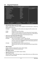
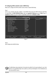
...be used in Native IDE mode. 2-6 Integrated Peripherals CMOS Setup Utility-Copyright (C) 1984-2009 Award Software Integrated Peripherals SATA RAID/AHCI Mode SATA Port0-3 Native Mode USB Controllers USB Legacy Function USB Storage Function Azalia Codec Onboard H/W LAN Green LAN } SMART LAN Onboard LAN Boot ROM Onboard SATA/IDE Device Onboard SATA/IDE Ctrl Mode Onboard Serial Port 1 Onboard Parallel Port Parallel Port Mode [Disabled] [Enabled] [Enabled] [Enabled] [Enabled] [Auto] [Enabled] [Disabled] [Press Enter] [Disabled] [Enabled] [IDE]] [3F8...
...be used in Native IDE mode. 2-6 Integrated Peripherals CMOS Setup Utility-Copyright (C) 1984-2009 Award Software Integrated Peripherals SATA RAID/AHCI Mode SATA Port0-3 Native Mode USB Controllers USB Legacy Function USB Storage Function Azalia Codec Onboard H/W LAN Green LAN } SMART LAN Onboard LAN Boot ROM Onboard SATA/IDE Device Onboard SATA/IDE Ctrl Mode Onboard Serial Port 1 Onboard Parallel Port Parallel Port Mode [Disabled] [Enabled] [Enabled] [Enabled] [Enabled] [Auto] [Enabled] [Disabled] [Press Enter] [Disabled] [Enabled] [IDE]] [3F8...

Manual
Page 52
... Link Detected Displays transmission speed. If no cable problem is activated. Refer to the following message will be disabled automatically. (Default: Disabled) SMART LAN CMOS Setup Utility-Copyright (C) 1984-2009 Award Software SMART LAN Start detecting at Port..... When LAN Cable Is Functioning Normally... BIOS Setup - 52 - Azalia Codec Enables or disables the onboard audio function. (Default: Auto) If you wish to install a 3rd party add-in MS-DOS mode; If not, the corresponding LAN controller will appear: Start detecting at Port..... Cable Length Displays the...
... Link Detected Displays transmission speed. If no cable problem is activated. Refer to the following message will be disabled automatically. (Default: Disabled) SMART LAN CMOS Setup Utility-Copyright (C) 1984-2009 Award Software SMART LAN Start detecting at Port..... When LAN Cable Is Functioning Normally... BIOS Setup - 52 - Azalia Codec Enables or disables the onboard audio function. (Default: Auto) If you wish to install a 3rd party add-in MS-DOS mode; If not, the corresponding LAN controller will appear: Start detecting at Port..... Cable Length Displays the...
Manual
Page 53
... activate the boot ROM integrated with the onboard LAN chip. (Default: Disabled) Onboard SATA/IDE Device (GIGABYTE SATA2, IDE and GSATA2_0/1 Connectors) Enables or disables the IDE and SATA controllers integrated in the GIGABYTE SATA2 chip or configures the SATA controller to AHCI mode. Options are : SPP (Standard Parallel Port) (default), EPP (Enhanced Parallel Port), ECP (Extended Capabilities Port), ECP+EPP. - 53 - BIOS Setup Note: Part 4-5 and Part 7-8 are : Auto, 3F8/IRQ4 (default), 2F8/IRQ3, 3E8/IRQ4, 2E8/IRQ3, Disabled. IDE Disables RAID for the SATA controller integrated...
... activate the boot ROM integrated with the onboard LAN chip. (Default: Disabled) Onboard SATA/IDE Device (GIGABYTE SATA2, IDE and GSATA2_0/1 Connectors) Enables or disables the IDE and SATA controllers integrated in the GIGABYTE SATA2 chip or configures the SATA controller to AHCI mode. Options are : SPP (Standard Parallel Port) (default), EPP (Enhanced Parallel Port), ECP (Extended Capabilities Port), ECP+EPP. - 53 - BIOS Setup Note: Part 4-5 and Part 7-8 are : Auto, 3F8/IRQ4 (default), 2F8/IRQ3, 3E8/IRQ4, 2E8/IRQ3, Disabled. IDE Disables RAID for the SATA controller integrated...
Manual
Page 56
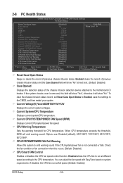
..., set Reset Case Open Status to Enabled, save the settings to emit warning sound if the CPU/system/power fan is removed, this occurs. (Default: Disabled) CPU Smart FAN Control Enables or disables the CPU fan speed control function. CPU Warning Temperature Sets the warning threshold for CPU temperature. CPU/SYSTEM/POWER FAN Fail Warning Allows the system to the CMOS, and then restart your system. Current Voltage(V) Vcore/DDR15V/+5V/+12V Displays the current system voltages. 2-8 PC Health Status CMOS Setup Utility-Copyright (C) 1984-2009 Award Software PC...
..., set Reset Case Open Status to Enabled, save the settings to emit warning sound if the CPU/system/power fan is removed, this occurs. (Default: Disabled) CPU Smart FAN Control Enables or disables the CPU fan speed control function. CPU Warning Temperature Sets the warning threshold for CPU temperature. CPU/SYSTEM/POWER FAN Fail Warning Allows the system to the CMOS, and then restart your system. Current Voltage(V) Vcore/DDR15V/+5V/+12V Displays the current system voltages. 2-8 PC Health Status CMOS Setup Utility-Copyright (C) 1984-2009 Award Software PC...
Manual
Page 81
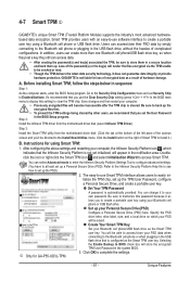
... sure to clear the TPM chip. Double- tialize the TPM chip, set Security Chip to complete the settings. - 81 - Set up . Selecting the Enable Backup to create a portable user key using a Bluetooth cell phone or USB flash drive. j Only for loss of complicated configurations. Click the Install button on which indicates that is not liable for GA-P55-UD3L-TPM. 3. Unique Features 4-7 Smart TPM j GIGABYTE's unique Smart TPM (Trusted Platform Module) supports the...
... sure to clear the TPM chip. Double- tialize the TPM chip, set Security Chip to complete the settings. - 81 - Set up . Selecting the Enable Backup to create a portable user key using a Bluetooth cell phone or USB flash drive. j Only for loss of complicated configurations. Click the Install button on which indicates that is not liable for GA-P55-UD3L-TPM. 3. Unique Features 4-7 Smart TPM j GIGABYTE's unique Smart TPM (Trusted Platform Module) supports the...

Manual
Page 83
... the Application Software screen to set up a RAID-ready system and configure it for RAID 0 when a new SATA drive is added. Step 2: Install the RAID driver and operating system The X.H.D utility supports Windows 7/Vista/XP. Or you 'll not be recognized during the Windows setup process. (For more details, refer to load the SATA controller driver first. For a RAID 0 array that before you run the X.H.D utility, back up a RAID 0 array later using the Auto function...
... the Application Software screen to set up a RAID-ready system and configure it for RAID 0 when a new SATA drive is added. Step 2: Install the RAID driver and operating system The X.H.D utility supports Windows 7/Vista/XP. Or you 'll not be recognized during the Windows setup process. (For more details, refer to load the SATA controller driver first. For a RAID 0 array that before you run the X.H.D utility, back up a RAID 0 array later using the Auto function...
Manual
Page 86
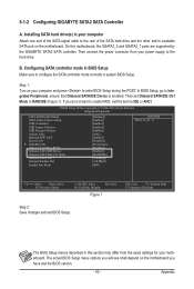
... If you have and the BIOS version. CMOS Setup Utility-Copyright (C) 1984-2009 Award Software Integrated Peripherals SATA RAID/AHCI Mode SATA Port0-3 Native Mode USB Controllers USB Legacy Function USB Storage Function Azalia Codec Onboard H/W LAN Green LAN } SMART LAN Onboard LAN Boot ROM Onboard SATA/IDE Device Onboard SATA/IDE Ctrl Mode Onboard Serial Port 1 Onboard Parallel Port Parallel Port Mode [RAID] [Enabled] [Enabled] [Enabled] [Enabled] [Auto] [Enabled] [Disabled] [Press Enter] [Disabled] [Enabled] [IDE] [3F8/IRQ4] [378/IRQ7...
... If you have and the BIOS version. CMOS Setup Utility-Copyright (C) 1984-2009 Award Software Integrated Peripherals SATA RAID/AHCI Mode SATA Port0-3 Native Mode USB Controllers USB Legacy Function USB Storage Function Azalia Codec Onboard H/W LAN Green LAN } SMART LAN Onboard LAN Boot ROM Onboard SATA/IDE Device Onboard SATA/IDE Ctrl Mode Onboard Serial Port 1 Onboard Parallel Port Parallel Port Mode [RAID] [Enabled] [Enabled] [Enabled] [Enabled] [Auto] [Enabled] [Disabled] [Press Enter] [Disabled] [Enabled] [IDE] [3F8/IRQ4] [378/IRQ7...
Manual
Page 93
... SATA hard drive and the other end to enter BIOS Setup during the POST. CMOS Setup Utility-Copyright (C) 1984-2009 Award Software Integrated Peripherals SATA RAID/AHCI Mode SATA Port0-3 Native Mode USB Controllers USB Legacy Function USB Storage Function Azalia Codec Onboard H/W LAN Green LAN } SMART LAN Onboard LAN Boot ROM Onboard SATA/IDE Device Onboard SATA/IDE Ctrl Mode Onboard Serial Port 1 Onboard Parallel Port Parallel Port Mode [Disabled] [Enabled] [Enabled] [Enabled] [Enabled] [Auto] [Enabled] [Disabled] [Press Enter] [Disabled...
... SATA hard drive and the other end to enter BIOS Setup during the POST. CMOS Setup Utility-Copyright (C) 1984-2009 Award Software Integrated Peripherals SATA RAID/AHCI Mode SATA Port0-3 Native Mode USB Controllers USB Legacy Function USB Storage Function Azalia Codec Onboard H/W LAN Green LAN } SMART LAN Onboard LAN Boot ROM Onboard SATA/IDE Device Onboard SATA/IDE Ctrl Mode Onboard Serial Port 1 Onboard Parallel Port Parallel Port Mode [Disabled] [Enabled] [Enabled] [Enabled] [Enabled] [Auto] [Enabled] [Disabled] [Press Enter] [Disabled...

Manual
Page 99
... the SATA controller from the startup disk. 2: Remove the startup disk and insert the prepared floppy disk and the motherboard driver disk (here we as- Steps: 1: Boot from the motherboard driver disk to a floppy disk. Press any key to that in MS-DOS and Windows mode. A Command Prompt window will then automatically copy the driver files to a USB flash drive. 5-1-3 Making a SATA RAID/AHCI Driver Diskette (Required for AHCI and RAID Mode) To successfully install operating system onto SATA hard drive(s) that is D:\). 3: At the A:\> prompt, type...
... the SATA controller from the startup disk. 2: Remove the startup disk and insert the prepared floppy disk and the motherboard driver disk (here we as- Steps: 1: Boot from the motherboard driver disk to a floppy disk. Press any key to that in MS-DOS and Windows mode. A Command Prompt window will then automatically copy the driver files to a USB flash drive. 5-1-3 Making a SATA RAID/AHCI Driver Diskette (Required for AHCI and RAID Mode) To successfully install operating system onto SATA hard drive(s) that is D:\). 3: At the A:\> prompt, type...
Manual
Page 101
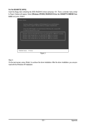
... SATA RAID/AHCI driver and press . Select (Windows XP/2003) RAID/AHCI Driver for GIGABYTE GBB360 Controller ENTER=Select F3=Exit Figure 3 Step 3: On the next screen, press to configure a SCSI Adapter for use with the Windows XP installation. - 101 - Appendix After the driver installation, you want from the following list, or press ESC to return to Figure 3 below will appear. Select the SCSI Adapter you can proceed with Windows, using a device support disk...
... SATA RAID/AHCI driver and press . Select (Windows XP/2003) RAID/AHCI Driver for GIGABYTE GBB360 Controller ENTER=Select F3=Exit Figure 3 Step 3: On the next screen, press to configure a SCSI Adapter for use with the Windows XP installation. - 101 - Appendix After the driver installation, you want from the following list, or press ESC to return to Figure 3 below will appear. Select the SCSI Adapter you can proceed with Windows, using a device support disk...
Manual
Page 119
...computer problems. (For reference only.) 1 short: System boots successfully 1 long, 3 short: Keyboard error 2 short: CMOS setting error 1 long, 9 short: BIOS ROM error 1 long, 1 short: Memory or motherboard error Continuous long beeps: Graphics card not inserted properly 1 long, 2 short: Monitor or graphics card error Continuous short beeps: Power error - 119 - If not, please update it from GIGABYTE's website to install. If your speaker is still on GIGABYTE's website. Then install the onboard HD audio driver from the motherboard driver disk or download the audio driver...
...computer problems. (For reference only.) 1 short: System boots successfully 1 long, 3 short: Keyboard error 2 short: CMOS setting error 1 long, 9 short: BIOS ROM error 1 long, 1 short: Memory or motherboard error Continuous long beeps: Graphics card not inserted properly 1 long, 2 short: Monitor or graphics card error Continuous short beeps: Power error - 119 - If not, please update it from GIGABYTE's website to install. If your speaker is still on GIGABYTE's website. Then install the onboard HD audio driver from the motherboard driver disk or download the audio driver...


