Manual
Page 4
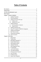
Table of Contents Box Contents...6 Optional Items...6 GA-P55-UD6 Motherboard Layout 7 Block Diagram...8 Chapter 1 Hardware Installation 9 1-1 Installation Precautions 9 1-2 Product Specifications 10 1-3 Installing the CPU and CPU Cooler 13 1-3-1 Installing the CPU 13 1-3-2 Installing the ... Defaults 63 2-10 Load Optimized Defaults 63 2-11 Set Supervisor/User Password 64 2-12 Save & Exit Setup 65 2-13 Exit Without Saving 65 2-14 Security Chip Configuration 66 - 4 -
Table of Contents Box Contents...6 Optional Items...6 GA-P55-UD6 Motherboard Layout 7 Block Diagram...8 Chapter 1 Hardware Installation 9 1-1 Installation Precautions 9 1-2 Product Specifications 10 1-3 Installing the CPU and CPU Cooler 13 1-3-1 Installing the CPU 13 1-3-2 Installing the ... Defaults 63 2-10 Load Optimized Defaults 63 2-11 Set Supervisor/User Password 64 2-12 Save & Exit Setup 65 2-13 Exit Without Saving 65 2-14 Security Chip Configuration 66 - 4 -
Manual
Page 10
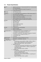
...2 x SATA 3Gb/s connectors (GSATA2_0/GSATA2_1) supporting up to 2 SATA 3Gb/s devices - Support for SATA RAID 0, RAID 1, RAID 5 and RAID 10 GIGABYTE SATA2 chip: - 1 x IDE connector supporting ATA-133/100/66/33 and up to 2 IDE devices - 2 x SATA 3Gb/s connectors (GSATA2_2, GSATA2_3) supporting up to...® Core™ i5 series processor in the LGA1156 package (Go to GIGABYTE's website for the latest CPU support list.) L3 cache varies with CPU Chipset Intel® P55 Express Chipset Memory 6 x 1.5V DDR3 DIMM sockets supporting up...
...2 x SATA 3Gb/s connectors (GSATA2_0/GSATA2_1) supporting up to 2 SATA 3Gb/s devices - Support for SATA RAID 0, RAID 1, RAID 5 and RAID 10 GIGABYTE SATA2 chip: - 1 x IDE connector supporting ATA-133/100/66/33 and up to 2 IDE devices - 2 x SATA 3Gb/s connectors (GSATA2_2, GSATA2_3) supporting up to...® Core™ i5 series processor in the LGA1156 package (Go to GIGABYTE's website for the latest CPU support list.) L3 cache varies with CPU Chipset Intel® P55 Express Chipset Memory 6 x 1.5V DDR3 DIMM sockets supporting up...

Manual
Page 11
... USB IEEE 1394 Internal w Connectors w w w w w w w w w w w w w w w w w w w Back Panel w Connectors w w w w w w w I/O Controller w iTE IT8720 chip: - 1 x floppy disk drive connector supporting up to 1 floppy disk drive Integrated in the Chipset Up to 14 USB 2.0/1.1 ports (10 on the back panel, 1 via... Speaker Out/Rear Speaker Out/ Side Speaker Out/Line In/Line Out/Microphone) iTE IT8720 chip - 11 -
... USB IEEE 1394 Internal w Connectors w w w w w w w w w w w w w w w w w w w Back Panel w Connectors w w w w w w w I/O Controller w iTE IT8720 chip: - 1 x floppy disk drive connector supporting up to 1 floppy disk drive Integrated in the Chipset Up to 14 USB 2.0/1.1 ports (10 on the back panel, 1 via... Speaker Out/Rear Speaker Out/ Side Speaker Out/Line In/Line Out/Microphone) iTE IT8720 chip - 11 -
Manual
Page 16
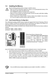
... DS/SS DS - - When enabling Dual Channel mode with six memory modules, make sure that memory of the same capacity, brand, speed, and chips be used. (Go to install it is installed, the BIOS will double the original memory bandwidth. DS/SS Four Modules - - DS/SS DS/SS... only one DDR3 memory module is installed, be enabled if only one direction. DS/SS - - - - Dual Channel mode cannot be sure to GIGABYTE's website for optimum performance. When enabling Dual Channel mode with two memory modules, be installed on the DDR3_3, DDR3_2, DDR3_6, DDR3_5 sockets are unable ...
... DS/SS DS - - When enabling Dual Channel mode with six memory modules, make sure that memory of the same capacity, brand, speed, and chips be used. (Go to install it is installed, the BIOS will double the original memory bandwidth. DS/SS Four Modules - - DS/SS DS/SS... only one DDR3 memory module is installed, be enabled if only one direction. DS/SS - - - - Dual Channel mode cannot be sure to GIGABYTE's website for optimum performance. When enabling Dual Channel mode with two memory modules, be installed on the DDR3_3, DDR3_2, DDR3_6, DDR3_5 sockets are unable ...
Manual
Page 19
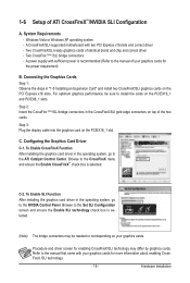
... Enable SLI Function After installing the graphics card driver in the CrossFireX/SLI gold edge connectors on your graphics cards. 1-6 Setup of identical brand and chip and correct driver - A power supply with sufficient power is recommended (Refer to the NVIDIA Control Panel. C. Browse to the manual that came with two PCI...
... Enable SLI Function After installing the graphics card driver in the CrossFireX/SLI gold edge connectors on your graphics cards. 1-6 Setup of identical brand and chip and correct driver - A power supply with sufficient power is recommended (Refer to the NVIDIA Control Panel. C. Browse to the manual that came with two PCI...
Manual
Page 39
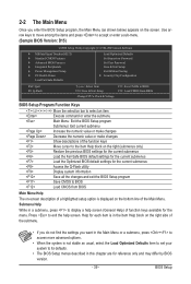
... PC Health Status Load Fail-Safe Defaults Load Optimized Defaults Set Supervisor Password Set User Password Save & Exit Setup Exit Without Saving Security Chip Configuration ESC: Quit F8: Q-Flash Select Item F10: Save & Exit Setup Change CPU's Clock & Voltage F11: Save CMOS to BIOS F12: Load CMOS from BIOS...
... PC Health Status Load Fail-Safe Defaults Load Optimized Defaults Set Supervisor Password Set User Password Save & Exit Setup Exit Without Saving Security Chip Configuration ESC: Quit F8: Q-Flash Select Item F10: Save & Exit Setup Change CPU's Clock & Voltage F11: Save CMOS to BIOS F12: Load CMOS from BIOS...

Manual
Page 40
... BIOS settings. First select the profile you to restrict access to the system and BIOS Setup. You can also carry out this task.) Security Chip Configuration Use this menu to configure the TPM function. It allows you to make changes. Save & Exit Setup Save all the changes made in...
... BIOS settings. First select the profile you to restrict access to the system and BIOS Setup. You can also carry out this task.) Security Chip Configuration Use this menu to configure the TPM function. It allows you to make changes. Save & Exit Setup Save all the changes made in...
Manual
Page 57
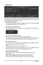
... F1: General Help F7: Optimized Defaults This motherboard incorporates cable diagnostic feature designed to activate the boot ROM integrated with the onboard LAN chip. (Default: Disabled) eSATA Controller (JMB362 Chip, eSATA Connectors on the Back Panel) Enables or disables the SATA controller integrated in Windows mode or when the LAN Boot ROM... length of the attached LAN cable. Note: The Gigabit hub will appear: Start detecting at a normal speed of 10/100/1000 Mbps in the JMB362 chip. (Default: Enabled) - 57 -
... F1: General Help F7: Optimized Defaults This motherboard incorporates cable diagnostic feature designed to activate the boot ROM integrated with the onboard LAN chip. (Default: Disabled) eSATA Controller (JMB362 Chip, eSATA Connectors on the Back Panel) Enables or disables the SATA controller integrated in Windows mode or when the LAN Boot ROM... length of the attached LAN cable. Note: The Gigabit hub will appear: Start detecting at a normal speed of 10/100/1000 Mbps in the JMB362 chip. (Default: Enabled) - 57 -
Manual
Page 58
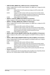
...BIOS Setup - 58 - GSATA 2_3/IDE Controller (GIGABYTE SATA2 Chip, IDE and GSATA2_2/3 Connectors) Enables or disables the IDE and SATA controller integrated in the GIGABYTE SATA2 chip. (Default: Enabled) GSATA 2_3/IDE Ctrl Mode (GIGABYTE SATA2 Chip, IDE and GSATA2_2/3 Connectors) Enables or disables RAID... for the SATA controller integrated in the GIGABYTE SATA2 chip or configures the SATA controller to AHCI mode...
...BIOS Setup - 58 - GSATA 2_3/IDE Controller (GIGABYTE SATA2 Chip, IDE and GSATA2_2/3 Connectors) Enables or disables the IDE and SATA controller integrated in the GIGABYTE SATA2 chip. (Default: Enabled) GSATA 2_3/IDE Ctrl Mode (GIGABYTE SATA2 Chip, IDE and GSATA2_2/3 Connectors) Enables or disables RAID... for the SATA controller integrated in the GIGABYTE SATA2 chip or configures the SATA controller to AHCI mode...

Manual
Page 63
...Peripherals Save & Exit Setup Power Management Setup PC Health Status Exit Without Saving Load Optimized Defaults(Y/NS)?ecNurity Chip Configuration Load Fail-Safe Defaults ESC: Quit F8: Q-Flash Select Item F10: Save & Exit Setup Load Optimized Defaults F11: Save ... Save & Exit Setup Power Management Setup PC Health Status Exit Without Saving Load Fail-Safe Defaults(Y/N)S?eNcurity Chip Configuration Load Fail-Safe Defaults ESC: Quit F8: Q-Flash Select Item F10: Save & Exit Setup Load Fail-Safe Defaults F11:...
...Peripherals Save & Exit Setup Power Management Setup PC Health Status Exit Without Saving Load Optimized Defaults(Y/NS)?ecNurity Chip Configuration Load Fail-Safe Defaults ESC: Quit F8: Q-Flash Select Item F10: Save & Exit Setup Load Optimized Defaults F11: Save ... Save & Exit Setup Power Management Setup PC Health Status Exit Without Saving Load Fail-Safe Defaults(Y/N)S?eNcurity Chip Configuration Load Fail-Safe Defaults ESC: Quit F8: Q-Flash Select Item F10: Save & Exit Setup Load Fail-Safe Defaults F11:...

Manual
Page 64
... Health Status Enter Password: Load Fail-Safe Defaults Load Optimized Defaults Set Supervisor Password Set User Password Save & Exit Setup Exit Without Saving Security Chip Configuration ESC: Quit F8: Q-Flash Select Item F10: Save & Exit Setup Change/Set/Disable Password F11: Save CMOS to BIOS F12: Load CMOS from BIOS...
... Health Status Enter Password: Load Fail-Safe Defaults Load Optimized Defaults Set Supervisor Password Set User Password Save & Exit Setup Exit Without Saving Security Chip Configuration ESC: Quit F8: Q-Flash Select Item F10: Save & Exit Setup Change/Set/Disable Password F11: Save CMOS to BIOS F12: Load CMOS from BIOS...

Manual
Page 65
...Save & Exit Setup Power Management Setup Exit Without Saving PC Health Status Save to CMOS and EXIT(Y/NS)e?cYurity Chip Configuration Load Fail-Safe Defaults ESC: Quit F8: Q-Flash Select Item F10: Save & Exit Setup Save Data to CMOS F11: Save ...Without Savin g (Y/N)?SNet User Password Save & Exit Setup Power Management Setup Exit Without Saving PC Health Status Security Chip Configuration Load Fail-Safe Defaults ESC: Quit F8: Q-Flash Select Item F10: Save & Exit Setup Abandon all Data F11: Save CMOS to BIOS ...
...Save & Exit Setup Power Management Setup Exit Without Saving PC Health Status Save to CMOS and EXIT(Y/NS)e?cYurity Chip Configuration Load Fail-Safe Defaults ESC: Quit F8: Q-Flash Select Item F10: Save & Exit Setup Save Data to CMOS F11: Save ...Without Savin g (Y/N)?SNet User Password Save & Exit Setup Power Management Setup Exit Without Saving PC Health Status Security Chip Configuration Load Fail-Safe Defaults ESC: Quit F8: Q-Flash Select Item F10: Save & Exit Setup Abandon all Data F11: Save CMOS to BIOS ...

Manual
Page 66
...: Select F5: Previous Values +/-/PU/PD: Value F10: Save F6: Fail-Safe Defaults ESC: Exit F1: General Help F7: Optimized Defaults Security Chip Enables or disables the security chip. Enabled/Activate Enables the security chip and initializes the Security Platform. It is recommended that you use this function with the Supervisor/ User password.
...: Select F5: Previous Values +/-/PU/PD: Value F10: Save F6: Fail-Safe Defaults ESC: Exit F1: General Help F7: Optimized Defaults Security Chip Enables or disables the security chip. Enabled/Activate Enables the security chip and initializes the Security Platform. It is recommended that you use this function with the Supervisor/ User password.

Manual
Page 74
... BIOS is @BIOS™? @BIOS allows you can access Q-Flash by adding one more physical BIOS chip. P55-UD6 D15 . . . . : BIOS Setup : XpressRecovery2 : Boot Menu : Qflash 07/07/2009-P55-7A89RG03C-00 Because BIOS flashing is saved to ensure normal system operation. Normally, the system works on ...the sake of system safety, users cannot update the backup BIOS manually. With Q-Flash you to access Q-Flash. Before You Begin 1. From GIGABYTE's website, download the latest compressed BIOS update file that support DualBIOS have two BIOS onboard, a main BIOS and a backup BIOS. p55ud6....
... BIOS is @BIOS™? @BIOS allows you can access Q-Flash by adding one more physical BIOS chip. P55-UD6 D15 . . . . : BIOS Setup : XpressRecovery2 : Boot Menu : Qflash 07/07/2009-P55-7A89RG03C-00 Because BIOS flashing is saved to ensure normal system operation. Normally, the system works on ...the sake of system safety, users cannot update the backup BIOS manually. With Q-Flash you to access Q-Flash. Before You Begin 1. From GIGABYTE's website, download the latest compressed BIOS update file that support DualBIOS have two BIOS onboard, a main BIOS and a backup BIOS. p55ud6....

Manual
Page 76
... User Password Integrated Peripherals Save & Exit Setup Power Management Setup PC Health Status Exit Without Saving Load Optimized Defaults(Y/NS)e?cYurity Chip Configuration Load Fail-Safe Defaults ESC: Quit F8: Q-Flash Select Item F10: Save & Exit Setup Load Optimized Defaults F11: Save CMOS to BIOS F12: Load...
... User Password Integrated Peripherals Save & Exit Setup Power Management Setup PC Health Status Exit Without Saving Load Optimized Defaults(Y/NS)e?cYurity Chip Configuration Load Fail-Safe Defaults ESC: Quit F8: Q-Flash Select Item F10: Save & Exit Setup Load Optimized Defaults F11: Save CMOS to BIOS F12: Load...

Manual
Page 85
Smart TPM provides users with an easy-to-use software interface to Enabled/Activate. GIGABYTE is not liable for using Smart TPM: 1. Go to the Security Chip Configuration menu and set Security Chip to create a portable user key using your Bluetooth cell phone or USB flash drive... Smart TPM interface allows users to install it does not guarantee data integrity or provide hardware protection. A. Unique Features 4-7 Smart TPM GIGABYTE's unique Smart TPM (Trusted Platform Module) supports the industry's most advanced hardwarebased data encryption. Click OK to access Smart TPM. Be...
Smart TPM provides users with an easy-to-use software interface to Enabled/Activate. GIGABYTE is not liable for using Smart TPM: 1. Go to the Security Chip Configuration menu and set Security Chip to create a portable user key using your Bluetooth cell phone or USB flash drive... Smart TPM interface allows users to install it does not guarantee data integrity or provide hardware protection. A. Unique Features 4-7 Smart TPM GIGABYTE's unique Smart TPM (Trusted Platform Module) supports the industry's most advanced hardwarebased data encryption. Click OK to access Smart TPM. Be...

Manual
Page 124
...no special specified, all H/W interrupts are MODBINable by a port & interface swap (optional) 3. Clear CMOS error flag 1. Reset keyboard Super I /O chips 2. Check validity of 5Ah is an invalid value for ESCD & DMI support Use walking 1's algorithm to see whether it is defined. Initialize 8042 ...Test CMOS R/W functionalitySix Modules Early chipset initialization: -Disable shadow RAM - Test special keyboard controller for Winbond 977 series Super I /O chips Test F000h segment shadow to check out interface in F000 for RTC minute 2. Also set real-time clock power status, and then...
...no special specified, all H/W interrupts are MODBINable by a port & interface swap (optional) 3. Clear CMOS error flag 1. Reset keyboard Super I /O chips 2. Check validity of 5Ah is an invalid value for ESCD & DMI support Use walking 1's algorithm to see whether it is defined. Initialize 8042 ...Test CMOS R/W functionalitySix Modules Early chipset initialization: -Disable shadow RAM - Test special keyboard controller for Winbond 977 series Super I /O chips Test F000h segment shadow to check out interface in F000 for RTC minute 2. Also set real-time clock power status, and then...

Manual
Page 125
Assign memory & I /O chips. Winbond 977 series Super I /O resource - Calculate total memory by testing the last double word of each CPU are not identical Initialize USB Keyboard & Mouse Test ...
Assign memory & I /O chips. Winbond 977 series Super I /O resource - Calculate total memory by testing the last double word of each CPU are not identical Initialize USB Keyboard & Mouse Test ...


