Manual
Page 4
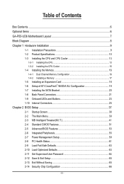
Table of Contents Box Contents...6 Optional Items...6 GA-P55-UD6 Motherboard Layout 7 Block Diagram...8 Chapter 1 Hardware Installation 9 1-1 Installation Precautions 9 1-2 Product Specifications 10 1-3 Installing the CPU and CPU Cooler 13 1-3-1 Installing the CPU 13 1-3-2 Installing the CPU Cooler 15 1-4 Installing the Memory 16 1-4-1 Dual Channel Memory Configuration 16 1-4-2 Installing a Memory 17 1-5 Installing an Expansion Card 18 1-6 Setup of ATI...
Table of Contents Box Contents...6 Optional Items...6 GA-P55-UD6 Motherboard Layout 7 Block Diagram...8 Chapter 1 Hardware Installation 9 1-1 Installation Precautions 9 1-2 Product Specifications 10 1-3 Installing the CPU and CPU Cooler 13 1-3-1 Installing the CPU 13 1-3-2 Installing the CPU Cooler 15 1-4 Installing the Memory 16 1-4-1 Dual Channel Memory Configuration 16 1-4-2 Installing a Memory 17 1-5 Installing an Expansion Card 18 1-6 Setup of ATI...

Manual
Page 8
Block Diagram 2 PCI Express x8 1 PCI Express x16 LGA1156 or CPU CPU CLK+/- (133 MHz) DDR3 2200/1333/1066/800 MHz Dual Channel Memory PCIe CLK (100 MHz) x8 x16 Switch PCI Express Bus LAN1 LAN2 PCIe ... x1 2 SATA 3Gb/s JMB362 2 SATA 3Gb/s ATA-133/100/66/33 IDE Channel PCI Bus x1 GIGABYTE SATA2 TSB43AB23 3 IEEE 1394a DMI Interface 1 PCI Express x4 3 PCI Express x1 2 SATA 3Gb/s or Intel® P55 x4 x1 JMB362 Switch PCIe CLK (100 MHz) PCI Express Bus Dual BIOS 6 SATA 3Gb/s 14 USB...
Block Diagram 2 PCI Express x8 1 PCI Express x16 LGA1156 or CPU CPU CLK+/- (133 MHz) DDR3 2200/1333/1066/800 MHz Dual Channel Memory PCIe CLK (100 MHz) x8 x16 Switch PCI Express Bus LAN1 LAN2 PCIe ... x1 2 SATA 3Gb/s JMB362 2 SATA 3Gb/s ATA-133/100/66/33 IDE Channel PCI Bus x1 GIGABYTE SATA2 TSB43AB23 3 IEEE 1394a DMI Interface 1 PCI Express x4 3 PCI Express x1 2 SATA 3Gb/s or Intel® P55 x4 x1 JMB362 Switch PCIe CLK (100 MHz) PCI Express Bus Dual BIOS 6 SATA 3Gb/s 14 USB...
Manual
Page 9
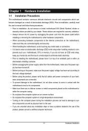
... 1 Hardware Installation 1-1 Installation Precautions The motherboard contains numerous delicate electronic circuits and components which can lead to damage to system components as well as a motherboard, CPU or memory. ponents such as physical harm to the user. • If you do not have an ESD wrist strap, keep your hands dry and...
... 1 Hardware Installation 1-1 Installation Precautions The motherboard contains numerous delicate electronic circuits and components which can lead to damage to system components as well as a motherboard, CPU or memory. ponents such as physical harm to the user. • If you do not have an ESD wrist strap, keep your hands dry and...
Manual
Page 10
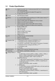
...processor/Intel® Core™ i5 series processor in the LGA1156 package (Go to GIGABYTE's website for the latest CPU support list.) L3 cache varies with CPU Chipset Intel® P55 Express Chipset Memory 6 x 1.5V DDR3 DIMM sockets supporting up to 16...memory modules Support for non-ECC memory modules Support for Extreme Memory Profile (XMP) memory modules (Go to GIGABYTE's website for the latest memory support list.) Audio Realtek ALC889A codec High Definition Audio 2/4/5.1/7.1-channel ...
...processor/Intel® Core™ i5 series processor in the LGA1156 package (Go to GIGABYTE's website for the latest CPU support list.) L3 cache varies with CPU Chipset Intel® P55 Express Chipset Memory 6 x 1.5V DDR3 DIMM sockets supporting up to 16...memory modules Support for non-ECC memory modules Support for Extreme Memory Profile (XMP) memory modules (Go to GIGABYTE's website for the latest memory support list.) Audio Realtek ALC889A codec High Definition Audio 2/4/5.1/7.1-channel ...

Manual
Page 11
... internal IEEE 1394a header) 1 x 24-pin ATX main power connector 1 x 8-pin ATX 12V power connector 1 x floppy disk drive connector 1 x IDE connector 10 x SATA 3Gb/s connectors 1 x CPU fan header 3 x system fan headers 1 x power fan header 1 x Chipset fan header 1 x front panel header 1 x front panel audio header 1 x CD In connector 1 x S/PDIF In header 1 x S/PDIF...
... internal IEEE 1394a header) 1 x 24-pin ATX main power connector 1 x 8-pin ATX 12V power connector 1 x floppy disk drive connector 1 x IDE connector 10 x SATA 3Gb/s connectors 1 x CPU fan header 3 x system fan headers 1 x power fan header 1 x Chipset fan header 1 x front panel header 1 x front panel audio header 1 x CD In connector 1 x S/PDIF In header 1 x S/PDIF...

Manual
Page 12
... the operating bandwidth for the PCIEX4_1 slot.) (Note 5) Whether the CPU/system fan speed control function is supported will depend on the CPU/system cooler you install. (Note 6) Available functions in EasyTune may ... Unique Features w w w w w w w w w w w Bundled Software w System voltage detection CPU/System temperature detection CPU/System/Power fan speed detection CPU overheating warning CPU/System/Power fan fail warning CPU/System fan speed control (Note 5) 2 x 16 Mbit flash Use of licensed AWARD BIOS Support for DualBIOS...
... the operating bandwidth for the PCIEX4_1 slot.) (Note 5) Whether the CPU/system fan speed control function is supported will depend on the CPU/system cooler you install. (Note 6) Available functions in EasyTune may ... Unique Features w w w w w w w w w w w Bundled Software w System voltage detection CPU/System temperature detection CPU/System/Power fan speed detection CPU overheating warning CPU/System/Power fan fail warning CPU/System fan speed control (Note 5) 2 x 16 Mbit flash Use of licensed AWARD BIOS Support for DualBIOS...

Manual
Page 13
... the notches on both sides of the CPU and alignment keys on the CPU socket.) • Apply an even and thin layer of thermal grease on the computer if the CPU cooler is not recommended that the motherboard supports the CPU. (Go to GIGABYTE's website for the peripherals. Locate the... alignment keys on the motherboard CPU socket and the notches on the CPU - 13 - age of the CPU Socket LGA1156 CPU Notch Notch Triangle Pin One ...
... the notches on both sides of the CPU and alignment keys on the CPU socket.) • Apply an even and thin layer of thermal grease on the computer if the CPU cooler is not recommended that the motherboard supports the CPU. (Go to GIGABYTE's website for the peripherals. Locate the... alignment keys on the motherboard CPU socket and the notches on the CPU - 13 - age of the CPU Socket LGA1156 CPU Notch Notch Triangle Pin One ...

Manual
Page 14
...be lifted as indicated and lift it up vertically. (DO NOT touch socket contacts. Step 5: Push the CPU socket lever back into the motherboard CPU socket. Step 4: Once the CPU is properly inserted, use the other to turn off the computer and unplug the power cord from the socket...When replacing the load plate, make sure to lightly replace the load plate. To protect the CPU socket, always replace the protective socket cover when the CPU is under the shoulder screw. NOTE: Hold the CPU socket lever by the handle, not the lever base portion. Step 2: Use your finger. ...
...be lifted as indicated and lift it up vertically. (DO NOT touch socket contacts. Step 5: Push the CPU socket lever back into the motherboard CPU socket. Step 4: Once the CPU is properly inserted, use the other to turn off the computer and unplug the power cord from the socket...When replacing the load plate, make sure to lightly replace the load plate. To protect the CPU socket, always replace the protective socket cover when the CPU is under the shoulder screw. NOTE: Hold the CPU socket lever by the handle, not the lever base portion. Step 2: Use your finger. ...

Manual
Page 15
... on the contrary, is complete. Step 6: Finally, attach the power connector of the installed CPU. Use extreme care when removing the CPU cooler because the thermal grease/tape between the CPU cooler and CPU may damage the CPU. - 15 - Check that the Male and Female push pins are joined closely. (Refer ...an even and thin layer of thermal grease on the surface of the CPU cooler to the CPU fan header (CPU_FAN) on the motherboard. Inadequately removing the CPU cooler may adhere to install.) Step 3: Place the cooler atop the CPU, aligning the four push pins through the pin holes on the male...
... on the contrary, is complete. Step 6: Finally, attach the power connector of the installed CPU. Use extreme care when removing the CPU cooler because the thermal grease/tape between the CPU cooler and CPU may damage the CPU. - 15 - Check that the Male and Female push pins are joined closely. (Refer ...an even and thin layer of thermal grease on the surface of the CPU cooler to the CPU fan header (CPU_FAN) on the motherboard. Inadequately removing the CPU cooler may adhere to install.) Step 3: Place the cooler atop the CPU, aligning the four push pins through the pin holes on the male...
Manual
Page 16
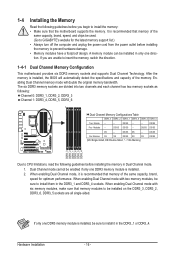
..., "- -"=No Memory) DS/SS DDR3_3 DDR3_2 DDR3_1 DDR3_6 DDR3_5 DDR3_4 Due to be sure to install the memory: • Make sure that memory modules to CPU limitations, read the following guidelines before installing the memory in the DDR3_1 or DDR3_4. 1-4 Installing the Memory Read the following guidelines before you are unable... enabled if only one DDR3 memory module is installed, the BIOS will double the original memory bandwidth. Dual Channel mode cannot be used. (Go to GIGABYTE's website for optimum performance.
..., "- -"=No Memory) DS/SS DDR3_3 DDR3_2 DDR3_1 DDR3_6 DDR3_5 DDR3_4 Due to be sure to install the memory: • Make sure that memory modules to CPU limitations, read the following guidelines before installing the memory in the DDR3_1 or DDR3_4. 1-4 Installing the Memory Read the following guidelines before you are unable... enabled if only one DDR3 memory module is installed, the BIOS will double the original memory bandwidth. Dual Channel mode cannot be used. (Go to GIGABYTE's website for optimum performance.

Manual
Page 23
CPU VTT: GD1: Normal working conditions (green LED) GD2: Excessive overvoltage or overloading (yellow LED) Memory: MD1: Normal working conditions; the yellow LEDs will be illuminated ... system power status (S0, S1, S3, S4, S5) to prevent potential hardware damage due to indicate the phase status of the CPU VTT and memory. 1-9 Onboard LEDs and Buttons CPU VTT/Memory Phase Indicator LEDs This motherboard contains 4 phase indicator LEDs controlled by the system BIOS to improper plug/unplug actions. ACPI...
CPU VTT: GD1: Normal working conditions (green LED) GD2: Excessive overvoltage or overloading (yellow LED) Memory: MD1: Normal working conditions; the yellow LEDs will be illuminated ... system power status (S0, S1, S3, S4, S5) to prevent potential hardware damage due to indicate the phase status of the CPU VTT and memory. 1-9 Onboard LEDs and Buttons CPU VTT/Memory Phase Indicator LEDs This motherboard contains 4 phase indicator LEDs controlled by the system BIOS to improper plug/unplug actions. ACPI...

Manual
Page 24
... factory defaults (select Load Optimized Defaults) or manually configure the BIOS settings (refer to Chapter 4, "Dynamic Energy Saver™ 2," for BIOS configurations). The higher the CPU loading, the more details. To enable the PHASE LED display function, please first enable Dynamic Energy Saver™ 2. date information and BIOS configurations) and reset... the CMOS values (e.g. Quick Buttons This motherboard has 3 quick buttons: power button, reset button and clearing CMOS button. PHASE LED The Phase LEDs indicate the CPU loading. Hardware Installation - 24 -
... factory defaults (select Load Optimized Defaults) or manually configure the BIOS settings (refer to Chapter 4, "Dynamic Energy Saver™ 2," for BIOS configurations). The higher the CPU loading, the more details. To enable the PHASE LED display function, please first enable Dynamic Energy Saver™ 2. date information and BIOS configurations) and reset... the CMOS values (e.g. Quick Buttons This motherboard has 3 quick buttons: power button, reset button and clearing CMOS button. PHASE LED The Phase LEDs indicate the CPU loading. Hardware Installation - 24 -
Manual
Page 26
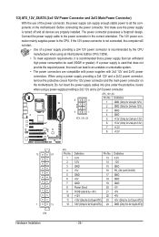
... GND GND -5V +5V +5V +5V (Only for 2x12-pin ATX) GND (Only for 2x12-pin ATX) - 26 - Connect the power supply cable to the CPU. When using a power supply providing a 2x2 12V and a 2x10 power connector. 8 4 5 1 ATX_12V_2X ATX_12V_2X: Pin No. The 12V power connector mainly supplies power to .... 3.3V 13 3.3V 14 GND 15 +5V 16 GND 17 +5V 18 GND 19 Power Good 20 5VSB (stand by the CPU manufacturer when using an Intel Extreme Edition CPU (130W). • To meet expansion requirements, it is recommended that a power supply that does not provide the required power, the ...
... GND GND -5V +5V +5V +5V (Only for 2x12-pin ATX) GND (Only for 2x12-pin ATX) - 26 - Connect the power supply cable to the CPU. When using a power supply providing a 2x2 12V and a 2x10 power connector. 8 4 5 1 ATX_12V_2X ATX_12V_2X: Pin No. The 12V power connector mainly supplies power to .... 3.3V 13 3.3V 14 GND 15 +5V 16 GND 17 +5V 18 GND 19 Power Good 20 5VSB (stand by the CPU manufacturer when using an Intel Extreme Edition CPU (130W). • To meet expansion requirements, it is recommended that a power supply that does not provide the required power, the ...
Manual
Page 27
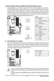
... / Speed Control 3 Sense 4 Reserve SYS_FAN1/SYS_FAN3/PWR_FAN: Pin No. The black connector wire is recommended that a system fan be sure to the CPU/Chipset or the system may result in damage to connect it in the correct orientation (the black connector wire is the ground wire). Overheating may... inside the chassis. Definition 1 1 GND 2 +12V 3 NC • Be sure to connect fan cables to the fan headers to prevent your CPU, Chipset and system from overheating. Do not place a jumper cap on the headers. - 27 - The fan header has a foolproof insertion design. The motherboard...
... / Speed Control 3 Sense 4 Reserve SYS_FAN1/SYS_FAN3/PWR_FAN: Pin No. The black connector wire is recommended that a system fan be sure to the CPU/Chipset or the system may result in damage to connect it in the correct orientation (the black connector wire is the ground wire). Overheating may... inside the chassis. Definition 1 1 GND 2 +12V 3 NC • Be sure to connect fan cables to the fan headers to prevent your CPU, Chipset and system from overheating. Do not place a jumper cap on the headers. - 27 - The fan header has a foolproof insertion design. The motherboard...
Manual
Page 39
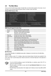
... Password Set User Password Save & Exit Setup Exit Without Saving Security Chip Configuration ESC: Quit F8: Q-Flash Select Item F10: Save & Exit Setup Change CPU's Clock & Voltage F11: Save CMOS to BIOS F12: Load CMOS from BIOS BIOS Setup Program Function Keys Move the selection bar to select an item...
... Password Set User Password Save & Exit Setup Exit Without Saving Security Chip Configuration ESC: Quit F8: Q-Flash Select Item F10: Save & Exit Setup Change CPU's Clock & Voltage F11: Save CMOS to BIOS F12: Load CMOS from BIOS BIOS Setup Program Function Keys Move the selection bar to select an item...

Manual
Page 40
... BIOS Setup. (Pressing can create up to configure the TPM function. It allows you to restrict access to see information about autodetected system/CPU temperature, system voltage and fan speed, etc. Load Fail-Safe Defaults Fail-Safe defaults are factory settings for the most stable,...that stop the system boot, etc. Advanced BIOS Features Use this menu to configure the device boot order, advanced features available on the CPU, and the primary display adapter. Integrated Peripherals Use this menu to configure all peripheral devices, such as IDE, SATA, USB, integrated...
... BIOS Setup. (Pressing can create up to configure the TPM function. It allows you to restrict access to see information about autodetected system/CPU temperature, system voltage and fan speed, etc. Load Fail-Safe Defaults Fail-Safe defaults are factory settings for the most stable,...that stop the system boot, etc. Advanced BIOS Features Use this menu to configure the device boot order, advanced features available on the CPU, and the primary display adapter. Integrated Peripherals Use this menu to configure all peripheral devices, such as IDE, SATA, USB, integrated...
Manual
Page 41
...Press Enter] [Press Enter] [Press Enter] Item Help Menu Level BIOS Version BCLK CPU Frequency Memory Frequency Total Memory Size CPU Temperature PCH Temperature Vcore DRAM Voltage D15 133.27 MHz 3198.42 MHz 1332.80 MHz 1024... (Mhz) C.I .T. Incorrectly doing overclock/overvoltage may result in damage to default values.) M.I .A.2 >>>>> Advanced Clock Control CPU Clock Drive PCI Express Clock Drive CPU Clock Skew [22X] 2.93GHz (133x22) [Press Enter] [Auto] 4.8GHz 18x 2400MHz [Disabled] 133 [Disabled] [Auto] 1333...
...Press Enter] [Press Enter] [Press Enter] Item Help Menu Level BIOS Version BCLK CPU Frequency Memory Frequency Total Memory Size CPU Temperature PCH Temperature Vcore DRAM Voltage D15 133.27 MHz 3198.42 MHz 1332.80 MHz 1024... (Mhz) C.I .T. Incorrectly doing overclock/overvoltage may result in damage to default values.) M.I .A.2 >>>>> Advanced Clock Control CPU Clock Drive PCI Express Clock Drive CPU Clock Skew [22X] 2.93GHz (133x22) [Press Enter] [Auto] 4.8GHz 18x 2400MHz [Disabled] 133 [Disabled] [Auto] 1333...
Manual
Page 42
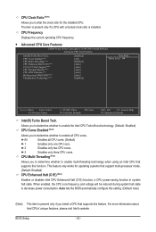
... Tech. Allows you to determine whether to enable the Intel CPU Turbo Boost technology. (Default: Enabled) CPU Cores Enabled (Note) Allows you to determine whether to enable all CPU cores. (Default) 1 Enables only one CPU core. 2 Enables only two CPU cores. 3 Enables only three CPU cores. CPU Clock Ratio (Note) Allows you to alter the clock ratio...
... Tech. Allows you to determine whether to enable the Intel CPU Turbo Boost technology. (Default: Enabled) CPU Cores Enabled (Note) Allows you to determine whether to enable all CPU cores. (Default) 1 Enables only one CPU core. 2 Enables only two CPU cores. 3 Enables only three CPU cores. CPU Clock Ratio (Note) Allows you to alter the clock ratio...

Manual
Page 43
...this setting. (Default: Auto) Bi-Directional PROCHOT (Note) Auto Lets the BIOS automatically configure this setting. (Default) Enabled When the CPU or chipset detects that supports this feature. Virtualization Technology (Note) Enables or disables Intel Virtualization Technology. QPI Link Speed Displays the current ... the Uncore clock ratio. (This ratio is fixed.) Uncore Frequency This value is occurring, PROCHOT signals will be reduced when the CPU is installed. Note: If your system fails to boot after overclocking, please wait for 20 seconds to allow for automated system reboot...
...this setting. (Default: Auto) Bi-Directional PROCHOT (Note) Auto Lets the BIOS automatically configure this setting. (Default) Enabled When the CPU or chipset detects that supports this feature. Virtualization Technology (Note) Enables or disables Intel Virtualization Technology. QPI Link Speed Displays the current ... the Uncore clock ratio. (This ratio is fixed.) Uncore Frequency This value is occurring, PROCHOT signals will be reduced when the CPU is installed. Note: If your system fails to boot after overclocking, please wait for 20 seconds to allow for automated system reboot...

Manual
Page 44
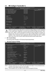
... verify the overclocking capability of the PCI Express and Chipset clock. Warning: Before using C.I .A.2. (Default) Cruise Increases CPU frequency by 5% or 7% depending on CPU loading. System Memory Multiplier (SPD) Allows you to set the PCIe clock frequency. PCI Express Frequency(Mhz) Allows you...manually set the system memory multiplier. C.I .A.2) is from 100 MHz to adjust the amplitude of your system hardware components. Turbo Increases CPU frequency by 9% or 11% depending on XMP memory module(s) to enhance memory performance when enabled. BIOS Setup - 44 - BCLK ...
... verify the overclocking capability of the PCI Express and Chipset clock. Warning: Before using C.I .A.2. (Default) Cruise Increases CPU frequency by 5% or 7% depending on CPU loading. System Memory Multiplier (SPD) Allows you to set the PCIe clock frequency. PCI Express Frequency(Mhz) Allows you...manually set the system memory multiplier. C.I .A.2) is from 100 MHz to adjust the amplitude of your system hardware components. Turbo Increases CPU frequency by 9% or 11% depending on XMP memory module(s) to enhance memory performance when enabled. BIOS Setup - 44 - BCLK ...


