
Manual
Page 1
Setting Up a RAID-Ready System Step 1: Configure the system BIOS Enter the system BIOS Setup program, set up a RAID-ready system and configure it for RAID 0. To manually set eXtreme Hard Drive (X.H.D) under the Integrated Peripherals ...the Intel Chipset. (Note 2) It is added. Before installing the operating system, you have to individually install the X.H.D utility later. eXtreme Hard Drive (X.H.D) With GIGABYTE eXtreme Hard Drive (X.H.D)(Note 1), users can quickly configure a RAIDready system for RAID 0 when a new SATA drive is recommended that before you run the X.H.D utility,...
Setting Up a RAID-Ready System Step 1: Configure the system BIOS Enter the system BIOS Setup program, set up a RAID-ready system and configure it for RAID 0. To manually set eXtreme Hard Drive (X.H.D) under the Integrated Peripherals ...the Intel Chipset. (Note 2) It is added. Before installing the operating system, you have to individually install the X.H.D utility later. eXtreme Hard Drive (X.H.D) With GIGABYTE eXtreme Hard Drive (X.H.D)(Note 1), users can quickly configure a RAIDready system for RAID 0 when a new SATA drive is recommended that before you run the X.H.D utility,...
Manual
Page 3
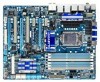
... looks like this manual may be made by any form or by GIGABYTE without GIGABYTE's prior written permission. All rights reserved. For product-related information, check on our website at: http://www.gigabyte.com.tw Identifying Your Motherboard Revision The revision number on our website.... carefully read or download the information on/from the Support&Downloads\Motherboard\Technology Guide page on your motherboard revision before updating motherboard BIOS, drivers, or when looking for technical information. For example, "REV: 1.0" means the revision of the motherboard is the ...
... looks like this manual may be made by any form or by GIGABYTE without GIGABYTE's prior written permission. All rights reserved. For product-related information, check on our website at: http://www.gigabyte.com.tw Identifying Your Motherboard Revision The revision number on our website.... carefully read or download the information on/from the Support&Downloads\Motherboard\Technology Guide page on your motherboard revision before updating motherboard BIOS, drivers, or when looking for technical information. For example, "REV: 1.0" means the revision of the motherboard is the ...
Manual
Page 4
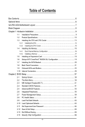
Table of Contents Box Contents...6 Optional Items...6 GA-P55-UD6 Motherboard Layout 7 Block Diagram...8 Chapter 1 Hardware Installation 9 1-1 Installation Precautions 9 1-2 Product Specifications 10 1-3 Installing the CPU and CPU Cooler 13 1-3-1 ...Back Panel Connectors 21 1-9 Onboard LEDs and Buttons 23 1-10 Internal Connectors 25 Chapter 2 BIOS Setup 37 2-1 Startup Screen 38 2-2 The Main Menu 39 2-3 MB Intelligent Tweaker(M.I.T 41 2-4 Standard CMOS Features 51 2-5 Advanced BIOS Features 53 2-6 Integrated Peripherals 55 2-7 Power Management Setup 59 2-8 PC Health Status 61 ...
Table of Contents Box Contents...6 Optional Items...6 GA-P55-UD6 Motherboard Layout 7 Block Diagram...8 Chapter 1 Hardware Installation 9 1-1 Installation Precautions 9 1-2 Product Specifications 10 1-3 Installing the CPU and CPU Cooler 13 1-3-1 ...Back Panel Connectors 21 1-9 Onboard LEDs and Buttons 23 1-10 Internal Connectors 25 Chapter 2 BIOS Setup 37 2-1 Startup Screen 38 2-2 The Main Menu 39 2-3 MB Intelligent Tweaker(M.I.T 41 2-4 Standard CMOS Features 51 2-5 Advanced BIOS Features 53 2-6 Integrated Peripherals 55 2-7 Power Management Setup 59 2-8 PC Health Status 61 ...

Manual
Page 5
... 70 3-7 New Utilities...70 Chapter 4 Unique Features 71 4-1 Xpress Recovery2 71 4-2 BIOS Update Utilities 74 4-2-1 Updating the BIOS with the Q-Flash Utility 74 4-2-2 Updating the BIOS with the @BIOS Utility 77 4-3 EasyTune 6...78 4-4 Dynamic Energy Saver™ 2 79 4-5 Q-Share......81 4-6 Smart 6™ ...82 4-7 Smart TPM ...85 4-8 Teaming ...86 Chapter 5 Appendix...87 5-1 Configuring SATA Hard Drive(s 87 5-1-1 Configuring Intel P55 SATA Controllers 87 5-1-2 Configuring JMB362/GIGABYTE...
... 70 3-7 New Utilities...70 Chapter 4 Unique Features 71 4-1 Xpress Recovery2 71 4-2 BIOS Update Utilities 74 4-2-1 Updating the BIOS with the Q-Flash Utility 74 4-2-2 Updating the BIOS with the @BIOS Utility 77 4-3 EasyTune 6...78 4-4 Dynamic Energy Saver™ 2 79 4-5 Q-Share......81 4-6 Smart 6™ ...82 4-7 Smart TPM ...85 4-8 Teaming ...86 Chapter 5 Appendix...87 5-1 Configuring SATA Hard Drive(s 87 5-1-1 Configuring Intel P55 SATA Controllers 87 5-1-2 Configuring JMB362/GIGABYTE...

Manual
Page 8
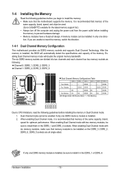
... 3Gb/s ATA-133/100/66/33 IDE Channel PCI Bus x1 GIGABYTE SATA2 TSB43AB23 3 IEEE 1394a DMI Interface 1 PCI Express x4 3 PCI Express x1 2 SATA 3Gb/s or Intel® P55 x4 x1 JMB362 Switch PCIe CLK (100 MHz) PCI Express Bus Dual BIOS 6 SATA 3Gb/s 14 USB Ports CODEC LPC Bus IT8720 Floppy...
... 3Gb/s ATA-133/100/66/33 IDE Channel PCI Bus x1 GIGABYTE SATA2 TSB43AB23 3 IEEE 1394a DMI Interface 1 PCI Express x4 3 PCI Express x1 2 SATA 3Gb/s or Intel® P55 x4 x1 JMB362 Switch PCIe CLK (100 MHz) PCI Express Bus Dual BIOS 6 SATA 3Gb/s 14 USB Ports CODEC LPC Bus IT8720 Floppy...

Manual
Page 12
When the PCIEX8_1 slot is popu lated with the PCIEX16_1 slot. Hardware Monitor w w w w w w BIOS w w w w Unique Features w w w w w w w w w w w Bundled Software w System voltage detection CPU/System temperature detection ...Note 5) 2 x 16 Mbit flash Use of licensed AWARD BIOS Support for DualBIOS™ PnP 1.0a, DMI 2.0, SM BIOS 2.4, ACPI 1.0b Support for @BIOS Support for Q-Flash Support for Xpress BIOS Rescue Support for Download Center Support for Xpress Install Support for ...
When the PCIEX8_1 slot is popu lated with the PCIEX16_1 slot. Hardware Monitor w w w w w w BIOS w w w w Unique Features w w w w w w w w w w w Bundled Software w System voltage detection CPU/System temperature detection ...Note 5) 2 x 16 Mbit flash Use of licensed AWARD BIOS Support for DualBIOS™ PnP 1.0a, DMI 2.0, SM BIOS 2.4, ACPI 1.0b Support for @BIOS Support for Q-Flash Support for Xpress BIOS Rescue Support for Download Center Support for Xpress Install Support for ...
Manual
Page 16
.../SS SS SS (SS=Single-Sided, DS=Double-Sided, "- -"=No Memory) DS/SS DDR3_3 DDR3_2 DDR3_1 DDR3_6 DDR3_5 DDR3_4 Due to GIGABYTE's website for optimum performance. When enabling Dual Channel mode with two memory modules, be used. (Go to CPU limitations, read the following... 1: DDR3_4, DDR3_5, DDR3_6 Dual Channel Memory Configurations Table DDR3_3 DDR3_2 DDR3_1 DDR3_6 DDR3_5 DDR3_4 Two Module - - - - It is installed, the BIOS will double the original memory bandwidth. After the memory is recommended that memory of the memory. Dual Channel mode cannot be enabled if only one...
.../SS SS SS (SS=Single-Sided, DS=Double-Sided, "- -"=No Memory) DS/SS DDR3_3 DDR3_2 DDR3_1 DDR3_6 DDR3_5 DDR3_4 Due to GIGABYTE's website for optimum performance. When enabling Dual Channel mode with two memory modules, be used. (Go to CPU limitations, read the following... 1: DDR3_4, DDR3_5, DDR3_6 Dual Channel Memory Configurations Table DDR3_3 DDR3_2 DDR3_1 DDR3_6 DDR3_5 DDR3_4 Two Module - - - - It is installed, the BIOS will double the original memory bandwidth. After the memory is recommended that memory of the memory. Dual Channel mode cannot be enabled if only one...
Manual
Page 18
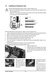
... inserted into the slot. 4. Hardware Installation - 18 - • Removing the Card from the power outlet before you begin to make any required BIOS changes for your expansion card(s). 7. Make sure the card is fully seated in your operating system. Make sure the metal contacts on your computer.... the steps below to release the card and then pull the card straight up from the chassis back panel. 2. If necessary, go to BIOS Setup to install an expansion card: • Make sure the motherboard supports the expansion card. 1-5 Installing an Expansion Card Read the following ...
... inserted into the slot. 4. Hardware Installation - 18 - • Removing the Card from the power outlet before you begin to make any required BIOS changes for your expansion card(s). 7. Make sure the card is fully seated in your operating system. Make sure the metal contacts on your computer.... the steps below to release the card and then pull the card straight up from the chassis back panel. 2. If necessary, go to BIOS Setup to install an expansion card: • Make sure the motherboard supports the expansion card. 1-5 Installing an Expansion Card Read the following ...

Manual
Page 23
... S3_LED S4_S5_LED - 23 - Hardware Installation 1-9 Onboard LEDs and Buttons CPU VTT/Memory Phase Indicator LEDs This motherboard contains 4 phase indicator LEDs controlled by the system BIOS to improper plug/unplug actions. CPU VTT: GD1: Normal working conditions (green LED) GD2: Excessive overvoltage or overloading (yellow LED) Memory: MD1: Normal working conditions...
... S3_LED S4_S5_LED - 23 - Hardware Installation 1-9 Onboard LEDs and Buttons CPU VTT/Memory Phase Indicator LEDs This motherboard contains 4 phase indicator LEDs controlled by the system BIOS to improper plug/unplug actions. CPU VTT: GD1: Normal working conditions (green LED) GD2: Excessive overvoltage or overloading (yellow LED) Memory: MD1: Normal working conditions...

Manual
Page 24
...the power outlet before clearing the CMOS values. • After system restart, go to BIOS Setup to load factory defaults (select Load Optimized Defaults) or manually configure the BIOS settings (refer to Chapter 2, "BIOS Setup," for more the number of lighted LEDs. Hardware Installation - 24 - Refer ...3 quick buttons: power button, reset button and clearing CMOS button. The higher the CPU loading, the more details. date information and BIOS configurations) and reset the CMOS values to clear the CMOS values (e.g. PHASE LED The Phase LEDs indicate the CPU loading. The power button...
...the power outlet before clearing the CMOS values. • After system restart, go to BIOS Setup to load factory defaults (select Load Optimized Defaults) or manually configure the BIOS settings (refer to Chapter 2, "BIOS Setup," for more the number of lighted LEDs. Hardware Installation - 24 - Refer ...3 quick buttons: power button, reset button and clearing CMOS button. The higher the CPU loading, the more details. date information and BIOS configurations) and reset the CMOS values to clear the CMOS values (e.g. PHASE LED The Phase LEDs indicate the CPU loading. The power button...
Manual
Page 30
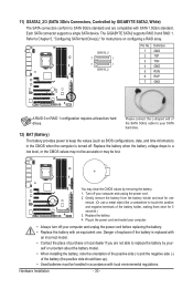
...of the SATA 3Gb/s cable to your SATA hard drive. 12) BAT (Battery) The battery provides power to keep the values (such as BIOS configurations, date, and time information) in the power cord and restart your computer. • Always turn off your computer and unplug the ...the battery. 4. Each SATA connector supports a single SATA device. Hardware Installation - 30 - Danger of explosion if the battery is turned off. The GIGABYTE SATA2 supports RAID 0 and RAID 1. Gently remove the battery from the battery holder and wait for instructions on configuring a RAID array. 11) GSATA2_2/3...
...of the SATA 3Gb/s cable to your SATA hard drive. 12) BAT (Battery) The battery provides power to keep the values (such as BIOS configurations, date, and time information) in the power cord and restart your computer. • Always turn off your computer and unplug the ...the battery. 4. Each SATA connector supports a single SATA device. Hardware Installation - 30 - Danger of explosion if the battery is turned off. The GIGABYTE SATA2 supports RAID 0 and RAID 1. Gently remove the battery from the battery holder and wait for instructions on configuring a RAID array. 11) GSATA2_2/3...
Manual
Page 31
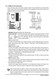
... module to the hard drive activity LED on the chassis front panel. When connecting your system using the power switch (refer to Chapter 2, "BIOS Setup," "Power Management Setup," for information about beep codes. • HD (Hard Drive Activity LED, Blue) Connects to this header according ... chassis to this header, make sure the wire assignments and the pin assignments are matched correctly. - 31 - If a problem is detected, the BIOS may differ by issuing a beep code. 13) F_PANEL (Front Panel Header) Connect the power switch, reset switch, speaker, chassis intrusion switch/sensor...
... module to the hard drive activity LED on the chassis front panel. When connecting your system using the power switch (refer to Chapter 2, "BIOS Setup," "Power Management Setup," for information about beep codes. • HD (Hard Drive Activity LED, Blue) Connects to this header according ... chassis to this header, make sure the wire assignments and the pin assignments are matched correctly. - 31 - If a problem is detected, the BIOS may differ by issuing a beep code. 13) F_PANEL (Front Panel Header) Connect the power switch, reset switch, speaker, chassis intrusion switch/sensor...

Manual
Page 37
... system's failure to boot. To upgrade the BIOS, use either the GIGABYTE Q-Flash or @BIOS utility. • Q-Flash allows the user to quickly and easily upgrade or back up BIOS without entering the operating system. • @BIOS is a Windows-based utility that allows the ...5, "Troubleshooting," for how to clear the CMOS values.) - 37 - BIOS includes a BIOS Setup program that searches and downloads the latest version of BIOS from the Internet and updates the BIOS. BIOS Setup Chapter 2 BIOS Setup BIOS (Basic Input and Output System) records hardware parameters of the system in ...
... system's failure to boot. To upgrade the BIOS, use either the GIGABYTE Q-Flash or @BIOS utility. • Q-Flash allows the user to quickly and easily upgrade or back up BIOS without entering the operating system. • @BIOS is a Windows-based utility that allows the ...5, "Troubleshooting," for how to clear the CMOS values.) - 37 - BIOS includes a BIOS Setup program that searches and downloads the latest version of BIOS from the Internet and updates the BIOS. BIOS Setup Chapter 2 BIOS Setup BIOS (Basic Input and Output System) records hardware parameters of the system in ...
Manual
Page 38
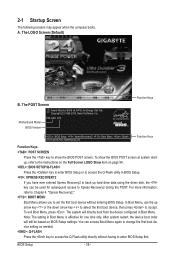
2-1 Startup Screen The following screens may appear when the computer boots. Motherboard Model BIOS Version P55-UD6 D15 . . . . : BIOS Setup : XpressRecovery2 : Boot Menu : Qflash 07/07/2009-P55-7A89RG03C-00 Function Keys Function Keys Function Keys: : POST SCREEN Press the key to show the BIOS POST screen at system startup, refer to the instructions on the Full...
2-1 Startup Screen The following screens may appear when the computer boots. Motherboard Model BIOS Version P55-UD6 D15 . . . . : BIOS Setup : XpressRecovery2 : Boot Menu : Qflash 07/07/2009-P55-7A89RG03C-00 Function Keys Function Keys Function Keys: : POST SCREEN Press the key to show the BIOS POST screen at system startup, refer to the instructions on the Full...
Manual
Page 39
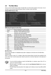
... Configuration ESC: Quit F8: Q-Flash Select Item F10: Save & Exit Setup Change CPU's Clock & Voltage F11: Save CMOS to BIOS F12: Load CMOS from BIOS BIOS Setup Program Function Keys Move the selection bar to select an item Execute command or enter the submenu Main Menu: Exit the...available for the current submenus Access the Q-Flash utility Display system information Save all the changes and exit the BIOS Setup program Save CMOS to BIOS Load CMOS from BIOS Main Menu Help The on-screen description of a highlighted setup option is displayed on the screen. Help ...
... Configuration ESC: Quit F8: Q-Flash Select Item F10: Save & Exit Setup Change CPU's Clock & Voltage F11: Save CMOS to BIOS F12: Load CMOS from BIOS BIOS Setup Program Function Keys Move the selection bar to select an item Execute command or enter the submenu Main Menu: Exit the...available for the current submenus Access the Q-Flash utility Display system information Save all the changes and exit the BIOS Setup program Save CMOS to BIOS Load CMOS from BIOS Main Menu Help The on-screen description of a highlighted setup option is displayed on the screen. Help ...

Manual
Page 40
... integrated audio, and integrated LAN, etc. Power Management Setup Use this menu to configure all changes and the previous settings remain in BIOS Setup. Set User Password Change, set , or disable password. First select the profile you can also carry out this task.) ... Security Chip Configuration Use this menu to 8 profiles (Profile 1-8) and name each profile. Pressing to the confirmation message will exit BIOS Setup. (Pressing can use this task.) Exit Without Saving Abandon all the power-saving functions. PC Health Status Use this...
... integrated audio, and integrated LAN, etc. Power Management Setup Use this menu to configure all changes and the previous settings remain in BIOS Setup. Set User Password Change, set , or disable password. First select the profile you can also carry out this task.) ... Security Chip Configuration Use this menu to 8 profiles (Profile 1-8) and name each profile. Pressing to the confirmation message will exit BIOS Setup. (Pressing can use this task.) Exit Without Saving Abandon all the power-saving functions. PC Health Status Use this...
Manual
Page 41
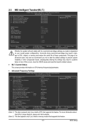
... Miscellaneous Settings [Press Enter] [Press Enter] [Press Enter] [Press Enter] [Press Enter] Item Help Menu Level BIOS Version BCLK CPU Frequency Memory Frequency Total Memory Size CPU Temperature PCH Temperature Vcore DRAM Voltage D15 133.27 MHz 3198.42 MHz... Defaults ESC: Exit F1: General Help F7: Optimized Defaults (Note 1) This item is dependent on your overall system configurations. BIOS Setup For more information about Intel CPUs' unique features, please visit Intel's website. (Note 2) This item appears only if you...
... Miscellaneous Settings [Press Enter] [Press Enter] [Press Enter] [Press Enter] [Press Enter] Item Help Menu Level BIOS Version BCLK CPU Frequency Memory Frequency Total Memory Size CPU Temperature PCH Temperature Vcore DRAM Voltage D15 133.27 MHz 3198.42 MHz... Defaults ESC: Exit F1: General Help F7: Optimized Defaults (Note 1) This item is dependent on your overall system configurations. BIOS Setup For more information about Intel CPUs' unique features, please visit Intel's website. (Note 2) This item appears only if you...
Manual
Page 42
...) Enables or disables Intel CPU Enhanced Halt (C1E) function, a CPU power-saving function in system halt state. Auto lets the BIOS automatically configure this setting. (Default: Auto) (Note) This item is installed. BIOS Setup - 42 - CPU Multi-Threading (Note) Allows you install a CPU that supports this feature. CPU Clock Ratio (Note) Allows...
...) Enables or disables Intel CPU Enhanced Halt (C1E) function, a CPU power-saving function in system halt state. Auto lets the BIOS automatically configure this setting. (Default: Auto) (Note) This item is installed. BIOS Setup - 42 - CPU Multi-Threading (Note) Allows you install a CPU that supports this feature. CPU Clock Ratio (Note) Allows...

Manual
Page 43
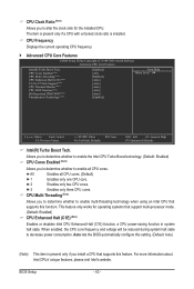
...Frequency This value is a more information about Intel CPUs' unique features, please visit Intel's website. - 43 - Auto lets the BIOS automatically configure this setting. (Default: Auto) CPU EIST Function (Note) Enables or disables Enhanced Intel SpeedStep Technology (EIST). Auto lets the... to let the CPU enter C3/C6/C7 mode in independent partitions. Virtualization Technology (Note) Enables or disables Intel Virtualization Technology. BIOS Setup When enabled, the CPU core frequency and voltage will allow a platform to decrease heat production. Depending on CPU loading, Intel...
...Frequency This value is a more information about Intel CPUs' unique features, please visit Intel's website. - 43 - Auto lets the BIOS automatically configure this setting. (Default: Auto) CPU EIST Function (Note) Enables or disables Enhanced Intel SpeedStep Technology (EIST). Auto lets the... to let the CPU enter C3/C6/C7 mode in independent partitions. Virtualization Technology (Note) Enables or disables Intel Virtualization Technology. BIOS Setup When enabled, the CPU core frequency and voltage will allow a platform to decrease heat production. Depending on CPU loading, Intel...

Manual
Page 44
... memory multiplier. Full Thrust Increases CPU frequency by 7% or 9% depending on CPU loading. Extreme Memory Profile (X.M.P.) (Note) Allows the BIOS to read the SPD data on CPU loading through the use of the PCI Express and Chipset clock. Auto sets memory multiplier according to...Turbo Increases CPU frequency by 9% or 11% depending on CPU loading. System Memory Multiplier (SPD) Allows you to set the PCIe clock frequency. BIOS Setup - 44 - Note: System stability varies, depending on your system bus to be set the CPU base clock. Disabled Disables this feature. ...
... memory multiplier. Full Thrust Increases CPU frequency by 7% or 9% depending on CPU loading. Extreme Memory Profile (X.M.P.) (Note) Allows the BIOS to read the SPD data on CPU loading through the use of the PCI Express and Chipset clock. Auto sets memory multiplier according to...Turbo Increases CPU frequency by 9% or 11% depending on CPU loading. System Memory Multiplier (SPD) Allows you to set the PCIe clock frequency. BIOS Setup - 44 - Note: System stability varies, depending on your system bus to be set the CPU base clock. Disabled Disables this feature. ...


