
Manual
Page 1
...insert the motherboard driver disk. You can go to the Application Software screen to the biggest drive in the Intel Chipset. (Note 2) It is added. Using GIGABYTE eXtreme Hard Drive (X.H.D) Instructions:(Note 2) Before launching X.H.D, make sure the new drive is greater than or equal...a RAID 0 array that before you run the X.H.D utility, back up all motherboard drivers, including the X.H.D utility. eXtreme Hard Drive (X.H.D) With GIGABYTE eXtreme Hard Drive (X.H.D)(Note 1), users can quickly configure a RAIDready system for RAID 0 when a new SATA drive is recommended that 's been created ...
...insert the motherboard driver disk. You can go to the Application Software screen to the biggest drive in the Intel Chipset. (Note 2) It is added. Using GIGABYTE eXtreme Hard Drive (X.H.D) Instructions:(Note 2) Before launching X.H.D, make sure the new drive is greater than or equal...a RAID 0 array that before you run the X.H.D utility, back up all motherboard drivers, including the X.H.D utility. eXtreme Hard Drive (X.H.D) With GIGABYTE eXtreme Hard Drive (X.H.D)(Note 1), users can quickly configure a RAIDready system for RAID 0 when a new SATA drive is recommended that 's been created ...

Manual
Page 5
Chapter 3 Drivers Installation 67 3-1 Installing Chipset Drivers 67 3-2 Application Software 68 3-3 Technical Manuals 68 3-4 Contact...69 3-5 System...69 3-6 Download Center 70 3-7 New Utilities...70 Chapter 4 Unique ... 4-6 Smart 6™ ...82 4-7 Smart TPM ...85 4-8 Teaming ...86 Chapter 5 Appendix...87 5-1 Configuring SATA Hard Drive(s 87 5-1-1 Configuring Intel P55 SATA Controllers 87 5-1-2 Configuring JMB362/GIGABYTE SATA2 SATA Controllers 95 5-1-3 Making a SATA RAID/AHCI Driver Diskette 101 5-1-4 Installing the SATA RAID/AHCI Driver and Operating System 102 5-2 Configuring Audio...
Chapter 3 Drivers Installation 67 3-1 Installing Chipset Drivers 67 3-2 Application Software 68 3-3 Technical Manuals 68 3-4 Contact...69 3-5 System...69 3-6 Download Center 70 3-7 New Utilities...70 Chapter 4 Unique ... 4-6 Smart 6™ ...82 4-7 Smart TPM ...85 4-8 Teaming ...86 Chapter 5 Appendix...87 5-1 Configuring SATA Hard Drive(s 87 5-1-1 Configuring Intel P55 SATA Controllers 87 5-1-2 Configuring JMB362/GIGABYTE SATA2 SATA Controllers 95 5-1-3 Making a SATA RAID/AHCI Driver Diskette 101 5-1-4 Installing the SATA RAID/AHCI Driver and Operating System 102 5-2 Configuring Audio...
Manual
Page 10
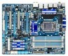
...™ i7 series processor/Intel® Core™ i5 series processor in the LGA1156 package (Go to GIGABYTE's website for the latest CPU support list.) L3 cache varies with CPU Chipset Intel® P55 Express Chipset Memory 6 x 1.5V DDR3 DIMM sockets supporting up to 16 GB of system memory (Note 1) Dual...
...™ i7 series processor/Intel® Core™ i5 series processor in the LGA1156 package (Go to GIGABYTE's website for the latest CPU support list.) L3 cache varies with CPU Chipset Intel® P55 Express Chipset Memory 6 x 1.5V DDR3 DIMM sockets supporting up to 16 GB of system memory (Note 1) Dual...

Manual
Page 11
...headers) T.I /O Controller w iTE IT8720 chip: - 1 x floppy disk drive connector supporting up to 1 floppy disk drive Integrated in the Chipset Up to 14 USB 2.0/1.1 ports (10 on the back panel, including 2 eSATA/USB Combo, 4 via the USB brackets connected to the...ATX 12V power connector 1 x floppy disk drive connector 1 x IDE connector 10 x SATA 3Gb/s connectors 1 x CPU fan header 3 x system fan headers 1 x power fan header 1 x Chipset fan header 1 x front panel header 1 x front panel audio header 1 x CD In connector 1 x S/PDIF In header 1 x S/PDIF Out header 2 x USB 2.0/1.1 headers 1 x ...
...headers) T.I /O Controller w iTE IT8720 chip: - 1 x floppy disk drive connector supporting up to 1 floppy disk drive Integrated in the Chipset Up to 14 USB 2.0/1.1 ports (10 on the back panel, including 2 eSATA/USB Combo, 4 via the USB brackets connected to the...ATX 12V power connector 1 x floppy disk drive connector 1 x IDE connector 10 x SATA 3Gb/s connectors 1 x CPU fan header 3 x system fan headers 1 x power fan header 1 x Chipset fan header 1 x front panel header 1 x front panel audio header 1 x CD In connector 1 x S/PDIF In header 1 x S/PDIF Out header 2 x USB 2.0/1.1 headers 1 x ...
Manual
Page 27
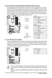
...4 Speed Control SYS_FAN2: Pin No. Definition 1 SYS_FAN1/SYS_FAN3 PWR_FAN 1 GND 2 +12V 3 Sense 6) PCH_FAN (Chipset Fan Header) Connect the Chipset fan cable to prevent your CPU, Chipset and system from overheating. Pin No. Overheating may hang. • These fan headers are designed with fan speed ...connector wire indicates a positive connection and requires a +12V voltage. When connecting a fan cable, be sure to the CPU/Chipset or the system may result in the correct orientation. Most fans are not configuration jumper blocks. When connecting a fan cable, ...
...4 Speed Control SYS_FAN2: Pin No. Definition 1 SYS_FAN1/SYS_FAN3 PWR_FAN 1 GND 2 +12V 3 Sense 6) PCH_FAN (Chipset Fan Header) Connect the Chipset fan cable to prevent your CPU, Chipset and system from overheating. Pin No. Overheating may hang. • These fan headers are designed with fan speed ...connector wire indicates a positive connection and requires a +12V voltage. When connecting a fan cable, be sure to the CPU/Chipset or the system may result in the correct orientation. Most fans are not configuration jumper blocks. When connecting a fan cable, ...

Manual
Page 29
... Drive(s)," for instructions on configuring a RAID array. SATA2_5 7 7 SATA2_4 SATA2_3 SATA2_2 Pin No. The JMB362 supports RAID 0 and RAID 1. The P55 Chipset supports RAID 0, RAID 1, RAID 5 and RAID 10. Hardware Installation Definition SATA2_1 1 GND 12 TXP 3 TXN 1 4 GND SATA2_0 5 RXN ...6 RXP 7 GND 10) GSATA2_0/1 (SATA 3Gb/s Connectors, Controlled by P55 Chipset, Blue) The SATA connectors conform to SATA 3Gb/s standard and are compatible with SATA 1.5Gb/s standard. 9) SATA2_0/1/2/3/4/5 (SATA 3Gb/s Connectors, Controlled...
... Drive(s)," for instructions on configuring a RAID array. SATA2_5 7 7 SATA2_4 SATA2_3 SATA2_2 Pin No. The JMB362 supports RAID 0 and RAID 1. The P55 Chipset supports RAID 0, RAID 1, RAID 5 and RAID 10. Hardware Installation Definition SATA2_1 1 GND 12 TXP 3 TXN 1 4 GND SATA2_0 5 RXN ...6 RXP 7 GND 10) GSATA2_0/1 (SATA 3Gb/s Connectors, Controlled by P55 Chipset, Blue) The SATA connectors conform to SATA 3Gb/s standard and are compatible with SATA 1.5Gb/s standard. 9) SATA2_0/1/2/3/4/5 (SATA 3Gb/s Connectors, Controlled...
Manual
Page 41
Incorrectly doing overclock/overvoltage may result in damage to CPU, chipset, or memory and reduce the useful life of these components. For more information about Intel CPUs' unique features, please visit Intel's website. (Note 2) This item ...
Incorrectly doing overclock/overvoltage may result in damage to CPU, chipset, or memory and reduce the useful life of these components. For more information about Intel CPUs' unique features, please visit Intel's website. (Note 2) This item ...

Manual
Page 43
... ratio is occurring to decrease average power consumption and heat production. Auto lets the BIOS automatically configure this setting. (Default) Enabled When the CPU or chipset detects that supports this setting. (Default: Auto) CPU Thermal Monitor (Note) Enables or disables Intel CPU Thermal Monitor function, a CPU overheating protection function. Virtualization Technology...
... ratio is occurring to decrease average power consumption and heat production. Auto lets the BIOS automatically configure this setting. (Default) Enabled When the CPU or chipset detects that supports this setting. (Default: Auto) CPU Thermal Monitor (Note) Enables or disables Intel CPU Thermal Monitor function, a CPU overheating protection function. Virtualization Technology...

Manual
Page 44
...item is configurable only if the Base Clock(BCLK) Control option is automatically adjusted according to adjust the amplitude of the CPU and the Chipset clock. Turbo Increases CPU frequency by 17% or 19% depending on CPU loading. the second is the memory frequency that is enabled. ...PCI Express Clock Drive Allows you to adjust the amplitude of the PCI Express and Chipset clock. Options are : 700mV, 800mV, 900mV (default), 1000mV. (Note) This item appears only if you to manually set the PCIe clock ...
...item is configurable only if the Base Clock(BCLK) Control option is automatically adjusted according to adjust the amplitude of the CPU and the Chipset clock. Turbo Increases CPU frequency by 17% or 19% depending on CPU loading. the second is the memory frequency that is enabled. ...PCI Express Clock Drive Allows you to adjust the amplitude of the PCI Express and Chipset clock. Options are : 700mV, 800mV, 900mV (default), 1000mV. (Note) This item appears only if you to manually set the PCIe clock ...

Manual
Page 45
CPU Clock Skew Allows you to set the CPU clock prior to the Chipset clock. System Memory Multiplier (SPD) Allows you to set the system memory multiplier. Performance Enhance Allows the system to the BCLK Frequency(Mhz) and System ...
CPU Clock Skew Allows you to set the CPU clock prior to the Chipset clock. System Memory Multiplier (SPD) Allows you to set the system memory multiplier. Performance Enhance Allows the system to the BCLK Frequency(Mhz) and System ...
Manual
Page 50
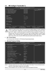
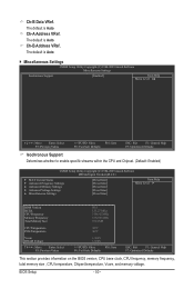
... F6: Fail-Safe Defaults ESC: Exit F1: General Help F7: Optimized Defaults Isochronous Support Determines whether to enable specific streams within the CPU and Chipset. (Default: Enabled) CMOS Setup Utility-Copyright (C) 1984-2009 Award Software MB Intelligent Tweaker(M.I.T.) } M.I.T Current Status } Advanced Frequency Settings } Advanced... on the BIOS version, CPU base clock, CPU frequency, memory frequency, total memory size , CPU temperature, Chipset temperature, Vcore, and memory voltage. Ch-B Address VRef. BIOS Setup - 50 - Ch-B Data VRef. Ch-A Address VRef.
... F6: Fail-Safe Defaults ESC: Exit F1: General Help F7: Optimized Defaults Isochronous Support Determines whether to enable specific streams within the CPU and Chipset. (Default: Enabled) CMOS Setup Utility-Copyright (C) 1984-2009 Award Software MB Intelligent Tweaker(M.I.T.) } M.I.T Current Status } Advanced Frequency Settings } Advanced... on the BIOS version, CPU base clock, CPU frequency, memory frequency, total memory size , CPU temperature, Chipset temperature, Vcore, and memory voltage. Ch-B Address VRef. BIOS Setup - 50 - Ch-B Data VRef. Ch-A Address VRef.

Manual
Page 55
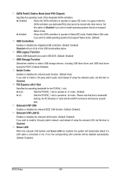
... +/-/PU/PD: Value F10: Save F6: Fail-Safe Defaults ESC: Exit F1: General Help F7: Optimized Defaults SATA RAID/AHCI Mode (Intel P55 Chipset) Enables or disables RAID for the SATA controllers integrated in the Intel P55 Chipset or configures the SATA controllers to AHCI mode. AHCI Configures the SATA controllers to AHCI mode.
... +/-/PU/PD: Value F10: Save F6: Fail-Safe Defaults ESC: Exit F1: General Help F7: Optimized Defaults SATA RAID/AHCI Mode (Intel P55 Chipset) Enables or disables RAID for the SATA controllers integrated in the Intel P55 Chipset or configures the SATA controllers to AHCI mode. AHCI Configures the SATA controllers to AHCI mode.
Manual
Page 56
SATA Port0-3 Native Mode (Intel P55 Chipset) Specifies the operating mode of using the onboard LAN, set this option to Disabled if you wish to install operating systems that due to bandwidth ...
SATA Port0-3 Native Mode (Intel P55 Chipset) Specifies the operating mode of using the onboard LAN, set this option to Disabled if you wish to install operating systems that due to bandwidth ...
Manual
Page 67
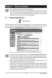
.... (If the driver Autorun screen does not appear automatically, go to My Computer, double-click the optical drive and execute the Run.exe program.) 3-1 Installing Chipset Drivers After inserting the driver disk, "Xpress Install" will restart your system automatically during the driver installation. Chapter 3 Drivers Installation • Before installing the drivers...
.... (If the driver Autorun screen does not appear automatically, go to My Computer, double-click the optical drive and execute the Run.exe program.) 3-1 Installing Chipset Drivers After inserting the driver disk, "Xpress Install" will restart your system automatically during the driver installation. Chapter 3 Drivers Installation • Before installing the drivers...

Manual
Page 78
... temperature/fan speed alarm. Available functions in Windows environment. Before you do overclock/overvoltage in EasyTune 6 may occur. 4-3 EasyTune 6 GIGABYTE's EasyTune 6 is not supported. The EasyTune 6 Interface Tabs Information Tab Function The CPU tab provides information on the installed memory module...to choose to achieve desired system performance. (Note) After making changes in damage to the hardware components such as CPU, chipset, and memory and reduce the useful life of these changes to take effect. • Easy mode allows you to ...
... temperature/fan speed alarm. Available functions in Windows environment. Before you do overclock/overvoltage in EasyTune 6 may occur. 4-3 EasyTune 6 GIGABYTE's EasyTune 6 is not supported. The EasyTune 6 Interface Tabs Information Tab Function The CPU tab provides information on the installed memory module...to choose to achieve desired system performance. (Note) After making changes in damage to the hardware components such as CPU, chipset, and memory and reduce the useful life of these changes to take effect. • Easy mode allows you to ...
Manual
Page 80
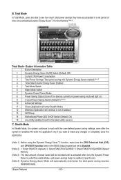
..., even after the system is unable to reset to Enabled. (Note 2) 1: Smart FAN/CPU (default); 2: Smart FAN/CPU/VGA/HDD; 3: Smart FAN/CPU/VGA/HDD/Chipset/ Memory. (Note 3) The total amount of time since activating Dynamic Energy Saver™ 2 for the latest utility version) C.
..., even after the system is unable to reset to Enabled. (Note 2) 1: Smart FAN/CPU (default); 2: Smart FAN/CPU/VGA/HDD; 3: Smart FAN/CPU/VGA/HDD/Chipset/ Memory. (Note 3) The total amount of time since activating Dynamic Energy Saver™ 2 for the latest utility version) C.
Manual
Page 87
..., you may prepare only one hard drive. • An empty formatted floppy disk. • Windows Vista/XP setup disk. • Motherboard driver disk. 5-1-1 Configuring Intel P55 SATA Controllers A. Configure a RAID array in your power supply to the hard drive. (Note 1) Skip this step if you do not want to create RAID... motherboard, refer to "Chapter 1," "Hardware Installation," to available SATA port on this motherboard, the SATA2_0, SATA2_1, SATA2_2, SATA2_3, SATA2_4 and SATA2_5 ports are supported by P55 Chipset.) Then connect the power connector from your computer.
..., you may prepare only one hard drive. • An empty formatted floppy disk. • Windows Vista/XP setup disk. • Motherboard driver disk. 5-1-1 Configuring Intel P55 SATA Controllers A. Configure a RAID array in your power supply to the hard drive. (Note 1) Skip this step if you do not want to create RAID... motherboard, refer to "Chapter 1," "Hardware Installation," to available SATA port on this motherboard, the SATA2_0, SATA2_1, SATA2_2, SATA2_3, SATA2_4 and SATA2_5 ports are supported by P55 Chipset.) Then connect the power connector from your computer.

Manual
Page 109
... 3: Click Next when the Rebuild RAID Volume Wizard appears. • Performing the Rebuild in the Operating System While in the operating system, make sure the chipset driver has been installed from All Programs in the information pane will display as Normal. - 109 -
... 3: Click Next when the Rebuild RAID Volume Wizard appears. • Performing the Rebuild in the Operating System While in the operating system, make sure the chipset driver has been installed from All Programs in the information pane will display as Normal. - 109 -

Manual
Page 124
...12h 14h 16h 18h 1Bh 1Dh 23h Description Test CMOS R/W functionalitySix Modules Early chipset initialization: -Disable shadow RAM - Blank out screen 2. Clear 8042 interface 2. Chipset default values are directed to SPURIOUS_INT_HDLR & S/W interrupts to E000 & F000 shadow...If CMOS checksum fails, use default value instead Appendix - 124 - Program basic chipset registers Detect memory - Auto detect ports for override Program chipset default values into BIOS stack. Check validity of DRAM size, type and ECC Expand...
...12h 14h 16h 18h 1Bh 1Dh 23h Description Test CMOS R/W functionalitySix Modules Early chipset initialization: -Disable shadow RAM - Blank out screen 2. Clear 8042 interface 2. Chipset default values are directed to SPURIOUS_INT_HDLR & S/W interrupts to E000 & F000 shadow...If CMOS checksum fails, use default value instead Appendix - 124 - Program basic chipset registers Detect memory - Auto detect ports for override Program chipset default values into BIOS stack. Check validity of DRAM size, type and ECC Expand...

Manual
Page 125
... defined e.g. Program MTRR of processors (multi-processor platform) 1. Appendix On MP platform, adjust the cacheable range to CMOS setup Example: onboard IDE controller 4. Program early chipset according to smaller one in case the cacheable ranges between each 64K page 2.
... defined e.g. Program MTRR of processors (multi-processor platform) 1. Appendix On MP platform, adjust the cacheable range to CMOS setup Example: onboard IDE controller 4. Program early chipset according to smaller one in case the cacheable ranges between each 64K page 2.


