
Manual
Page 1
...only supports the SATA controllers integrated in the array. ) 1. For a RAID 0 array that before you run the X.H.D utility, back up all motherboard drivers, including the X.H.D utility. Without the driver, the hard drive may not be able to automatically set up a RAID array: (Note 3): Click... has equal or greater capacity than or equal to enhance your needs and hardware components. 3. B. eXtreme Hard Drive (X.H.D) With GIGABYTE eXtreme Hard Drive (X.H.D)(Note 1), users can quickly configure a RAIDready system for complex and time-consuming configurations. All with which you...
...only supports the SATA controllers integrated in the array. ) 1. For a RAID 0 array that before you run the X.H.D utility, back up all motherboard drivers, including the X.H.D utility. Without the driver, the hard drive may not be able to automatically set up a RAID array: (Note 3): Click... has equal or greater capacity than or equal to enhance your needs and hardware components. 3. B. eXtreme Hard Drive (X.H.D) With GIGABYTE eXtreme Hard Drive (X.H.D)(Note 1), users can quickly configure a RAIDready system for complex and time-consuming configurations. All with which you...

Manual
Page 4
Some motherboard driver disks include the Smart TPM utility in "Xpress Install." Click the Install All button and "Xpress Install" will automatically scan your system and list ... it. Click the "Install All" button on the right of the selected drivers, including the Infineon TPM driver. 2.2. Installing the Infineon TPM Driver Insert the GIGABYTE motherboard driver disk.
Some motherboard driver disks include the Smart TPM utility in "Xpress Install." Click the Install All button and "Xpress Install" will automatically scan your system and list ... it. Click the "Install All" button on the right of the selected drivers, including the Infineon TPM driver. 2.2. Installing the Infineon TPM Driver Insert the GIGABYTE motherboard driver disk.

Manual
Page 7
... Refresh to search for pairing. If more than one USB flash drive at the same time. Before creating a Bluetooth cell phone key, make sure your motherboard includes a Bluetooth receiver and turn on the search and Bluetooth functions on your phone. Create a Bluetooth cell phone key: Select the Use Bluetooth Device check...
... Refresh to search for pairing. If more than one USB flash drive at the same time. Before creating a Bluetooth cell phone key, make sure your motherboard includes a Bluetooth receiver and turn on the search and Bluetooth functions on your phone. Create a Bluetooth cell phone key: Select the Use Bluetooth Device check...

Manual
Page 19
...'t display your Bluetooth-enabled cell phone, click Refresh to let Smart TPM re-detect the device.) Before creating a Bluetooth cell phone key, make sure your motherboard includes a Bluetooth receiver and turn off or reset your phone. - 19 - You are able to confirm, click Yes.
...'t display your Bluetooth-enabled cell phone, click Refresh to let Smart TPM re-detect the device.) Before creating a Bluetooth cell phone key, make sure your motherboard includes a Bluetooth receiver and turn off or reset your phone. - 19 - You are able to confirm, click Yes.

Manual
Page 1
GA-P55-UD4P GA-P55-UD4 LGA1156 socket motherboard for Intel® Core™ i7 processor family/ Intel® Core™ i5 processor family User's Manual Rev. 1001 12ME-P55UD4P-1001R
GA-P55-UD4P GA-P55-UD4 LGA1156 socket motherboard for Intel® Core™ i7 processor family/ Intel® Core™ i5 processor family User's Manual Rev. 1001 12ME-P55UD4P-1001R

Manual
Page 3
Changes to their respective owners. For example, "REV: 1.0" means the revision of the motherboard is the property of GIGABYTE. Documentation Classifications In order to use of this product, GIGABYTE provides the following types of documentations: For quick set-up of this : "REV: X.X."...; 2009 GIGA-BYTE TECHNOLOGY CO., LTD. For product-related information, check on our website at: http://www.gigabyte.com.tw Identifying Your Motherboard Revision The revision number on our website. For detailed product information, carefully read or download the information on/from...
Changes to their respective owners. For example, "REV: 1.0" means the revision of the motherboard is the property of GIGABYTE. Documentation Classifications In order to use of this product, GIGABYTE provides the following types of documentations: For quick set-up of this : "REV: X.X."...; 2009 GIGA-BYTE TECHNOLOGY CO., LTD. For product-related information, check on our website at: http://www.gigabyte.com.tw Identifying Your Motherboard Revision The revision number on our website. For detailed product information, carefully read or download the information on/from...

Manual
Page 4
Table of Contents Box Contents...6 Optional Items...6 GA-P55-UD4P/GA-P55-UD4 Motherboard Layout 7 Block Diagram...8 Chapter 1 Hardware Installation 9 1-1 Installation Precautions 9 1-2 Product Specifications 10 1-3 Installing the CPU and CPU Cooler 13 1-3-1 Installing the CPU 13 1-3-2 Installing the CPU ...
Table of Contents Box Contents...6 Optional Items...6 GA-P55-UD4P/GA-P55-UD4 Motherboard Layout 7 Block Diagram...8 Chapter 1 Hardware Installation 9 1-1 Installation Precautions 9 1-2 Product Specifications 10 1-3 Installing the CPU and CPU Cooler 13 1-3-1 Installing the CPU 13 1-3-2 Installing the CPU ...

Manual
Page 6
Box Contents GA-P55-UD4P or GA-P55-UD4 motherboard Motherboard driver disk User's Manual Quick Installation Guide One IDE cable Four SATA 3Gb/s cables 2-Way SLI bridge connector I/O Shield • The box contents above are subject to change without notice. • The motherboard image is for reference only and the actual items shall depend on the product package...
Box Contents GA-P55-UD4P or GA-P55-UD4 motherboard Motherboard driver disk User's Manual Quick Installation Guide One IDE cable Four SATA 3Gb/s cables 2-Way SLI bridge connector I/O Shield • The box contents above are subject to change without notice. • The motherboard image is for reference only and the actual items shall depend on the product package...

Manual
Page 7
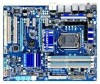
GA-P55-UD4P/GA-P55-UD4 Motherboard Layout KB_USB R_SPDIF CPU_FAN ATX_12V_2X4 USB_1394_ESATA_2 USB_1394_ESATA_1 LGA1156 USB_LAN2 j USB_LAN1 JMB362 RTL8111D AUDIO F_AUDIO SYS_FAN1 PCIEX1_1(Note) PCIEX16 RTL8111D j PCIEX1_2 CD_IN SPDIF_I SPDIF_O CODEC PCIEX1_3 PCIEX8 PCI1 BATTERY TPM IC j TSB43AB23 GA-P55-UD4P / GA-P55-UD4 DDR3_2 DDR3_1 PHASE LED ATX PWR_FAN IDE DDR3_4 DDR3_3 GIGABYTE SATA2 B_BIOS Intel® P55 M_BIOS SYS_FAN2 PCH_FAN CLR_CMOS GSATA2_1...
GA-P55-UD4P/GA-P55-UD4 Motherboard Layout KB_USB R_SPDIF CPU_FAN ATX_12V_2X4 USB_1394_ESATA_2 USB_1394_ESATA_1 LGA1156 USB_LAN2 j USB_LAN1 JMB362 RTL8111D AUDIO F_AUDIO SYS_FAN1 PCIEX1_1(Note) PCIEX16 RTL8111D j PCIEX1_2 CD_IN SPDIF_I SPDIF_O CODEC PCIEX1_3 PCIEX8 PCI1 BATTERY TPM IC j TSB43AB23 GA-P55-UD4P / GA-P55-UD4 DDR3_2 DDR3_1 PHASE LED ATX PWR_FAN IDE DDR3_4 DDR3_3 GIGABYTE SATA2 B_BIOS Intel® P55 M_BIOS SYS_FAN2 PCH_FAN CLR_CMOS GSATA2_1...

Manual
Page 9
...computer system on an uneven surface. • Do not place the computer system in a high-temperature environment. • Turning on the motherboard, make sure the power supply voltage has been set according to the local voltage standard. • Before using the product, please verify...remove the AC power by your hands dry and first touch a metal object to eliminate static electricity. • Prior to installing the motherboard, please have a problem related to wear an electrostatic discharge (ESD) wrist strap when handling electronic com- Hardware Installation Chapter 1 Hardware Installation ...
...computer system on an uneven surface. • Do not place the computer system in a high-temperature environment. • Turning on the motherboard, make sure the power supply voltage has been set according to the local voltage standard. • Before using the product, please verify...remove the AC power by your hands dry and first touch a metal object to eliminate static electricity. • Prior to installing the motherboard, please have a problem related to wear an electrostatic discharge (ESD) wrist strap when handling electronic com- Hardware Installation Chapter 1 Hardware Installation ...

Manual
Page 12
... Internet Security (OEM version) Operating System w Support for Microsoft® Windows® 7/Vista/XP Form Factor w ATX Form Factor; 30.5cm x 24.4cm j Only for GA-P55-UD4P. (Note 1) Due to Windows Vista/XP 32-bit operating system limitation, when more than 4 GB of physical memory is installed, the actual memory size displayed... x8 mode. (Note 4) Whether the CPU/system fan speed control function is to be installed, be sure to install it in EasyTune may differ by motherboard model.
... Internet Security (OEM version) Operating System w Support for Microsoft® Windows® 7/Vista/XP Form Factor w ATX Form Factor; 30.5cm x 24.4cm j Only for GA-P55-UD4P. (Note 1) Due to Windows Vista/XP 32-bit operating system limitation, when more than 4 GB of physical memory is installed, the actual memory size displayed... x8 mode. (Note 4) Whether the CPU/system fan speed control function is to be installed, be sure to install it in EasyTune may differ by motherboard model.

Manual
Page 13
... the CPU Socket LGA1156 CPU Notch Notch Triangle Pin One Marking on the computer if the CPU cooler is not recommended that the motherboard supports the CPU. (Go to GIGABYTE's website for the peripherals. Hardware Installation 1-3 Installing the CPU and CPU Cooler Read the following guidelines before you begin to install the... latest CPU support list.) • Always turn on the CPU - 13 - It is not installed, otherwise overheating and dam- Locate the alignment keys on the motherboard CPU socket and the notches on the CPU.
... the CPU Socket LGA1156 CPU Notch Notch Triangle Pin One Marking on the computer if the CPU cooler is not recommended that the motherboard supports the CPU. (Go to GIGABYTE's website for the peripherals. Hardware Installation 1-3 Installing the CPU and CPU Cooler Read the following guidelines before you begin to install the... latest CPU support list.) • Always turn on the CPU - 13 - It is not installed, otherwise overheating and dam- Locate the alignment keys on the motherboard CPU socket and the notches on the CPU.

Manual
Page 14
... lever by the handle, not the lever base portion. Step 2: Use your thumb and index fingers. B. Step 5: Push the CPU socket lever back into the motherboard CPU socket. Then completely lift the CPU socket lever and the metal load plate will be lifted as indicated and lift it up vertically. (DO...
... lever by the handle, not the lever base portion. Step 2: Use your thumb and index fingers. B. Step 5: Push the CPU socket lever back into the motherboard CPU socket. Then completely lift the CPU socket lever and the metal load plate will be lifted as indicated and lift it up vertically. (DO...

Manual
Page 15
...the cooler, on the contrary, is complete. Hardware Installation 1-3-2 Installing the CPU Cooler Follow the steps below to correctly install the CPU cooler on the motherboard. (The following procedure uses Intel® boxed cooler as the picture above shows, the installation is to install.) Step 3: Place the cooler atop ...the CPU, aligning the four push pins through the pin holes on the motherboard. Direction of the Arrow Sign on the Male Push Pin Male Push Pin The Top of Female Push Pin Female Push Pin Step 2: Before ...
...the cooler, on the contrary, is complete. Hardware Installation 1-3-2 Installing the CPU Cooler Follow the steps below to correctly install the CPU cooler on the motherboard. (The following procedure uses Intel® boxed cooler as the picture above shows, the installation is to install.) Step 3: Place the cooler atop ...the CPU, aligning the four push pins through the pin holes on the motherboard. Direction of the Arrow Sign on the Male Push Pin Male Push Pin The Top of Female Push Pin Female Push Pin Step 2: Before ...

Manual
Page 16
If you begin to insert the memory, switch the direction. 1-4-1 Dual Channel Memory Configuration This motherboard provides four DDR3 memory sockets and supports Dual Channel Technology. When enabling Dual Channel mode with two or four memory modules, it ...Enabling Dual Channel memory mode will automatically detect the specifications and capacity of the same capacity, brand, speed, and chips be used . (Go to GIGABYTE's website for optimum performance. 1-4 Installing the Memory Read the following guidelines before installing the memory in Dual Channel mode. 1. DS/SS Four Modules DS...
If you begin to insert the memory, switch the direction. 1-4-1 Dual Channel Memory Configuration This motherboard provides four DDR3 memory sockets and supports Dual Channel Technology. When enabling Dual Channel mode with two or four memory modules, it ...Enabling Dual Channel memory mode will automatically detect the specifications and capacity of the same capacity, brand, speed, and chips be used . (Go to GIGABYTE's website for optimum performance. 1-4 Installing the Memory Read the following guidelines before installing the memory in Dual Channel mode. 1. DS/SS Four Modules DS...

Manual
Page 17
... vertically into place when the memory module is securely inserted. - 17 - Follow the steps below to the memory module. Place the memory module on this motherboard.
... vertically into place when the memory module is securely inserted. - 17 - Follow the steps below to the memory module. Place the memory module on this motherboard.

Manual
Page 18
... with a screw. 5. PCI Express x1 Slot PCI Express x16 Slot PCI Slot Follow the steps below to install an expansion card: • Make sure the motherboard supports the expansion card.
... with a screw. 5. PCI Express x1 Slot PCI Express x16 Slot PCI Slot Follow the steps below to install an expansion card: • Make sure the motherboard supports the expansion card.

Manual
Page 19
... the graphics card on your graphics cards for the power requirement) B. Configuring the Graphics Card Driver C-1. Browse to the NVIDIA Control Panel. A CrossFireX/SLI-supported motherboard with your graphics cards. Procedure and driver screen for enabling CrossFireX/SLI technology may be needed or not depending on the PCIEX16 slot.
... the graphics card on your graphics cards for the power requirement) B. Configuring the Graphics Card Driver C-1. Browse to the NVIDIA Control Panel. A CrossFireX/SLI-supported motherboard with your graphics cards. Procedure and driver screen for enabling CrossFireX/SLI technology may be needed or not depending on the PCIEX16 slot.

Manual
Page 20
...audio. Hardware Installation - 20 - Optical S/PDIF Out Connector This connector provides digital audio out to Chapter 5, "Configuring SATA Hard Drive(s)," for GA-P55-UD4P. • When removing the cable connected to a back panel connector, first remove the cable from your audio system provides a coaxial digital audio... and hotplug capabilities. Refer to an external audio system that supports digital coaxial audio. Do not rock it straight out from the motherboard. • When removing the cable, pull it side to side to prevent an electrical short inside the cable connector. PS/2 ...
...audio. Hardware Installation - 20 - Optical S/PDIF Out Connector This connector provides digital audio out to Chapter 5, "Configuring SATA Hard Drive(s)," for GA-P55-UD4P. • When removing the cable connected to a back panel connector, first remove the cable from your audio system provides a coaxial digital audio... and hotplug capabilities. Refer to an external audio system that supports digital coaxial audio. Do not rock it straight out from the motherboard. • When removing the cable, pull it side to side to prevent an electrical short inside the cable connector. PS/2 ...

Manual
Page 22
... devices and your devices are compliant with the connectors you wish to connect. • Before installing the devices, be sure to the connector on the motherboard.
... devices and your devices are compliant with the connectors you wish to connect. • Before installing the devices, be sure to the connector on the motherboard.


