
Manual
Page 1
..., users also can use X.H.D to easily add a hard drive into a RAID 0 array that before you run the X.H.D utility, back up all motherboard drivers, including the X.H.D utility. A. Setting Up a RAID-Ready System Step 1: Configure the system BIOS Enter the system BIOS Setup program, set up...Without the driver, the hard drive may not be able to enhance your needs and hardware components. 3. eXtreme Hard Drive (X.H.D) With GIGABYTE eXtreme Hard Drive (X.H.D)(Note 1), users can quickly configure a RAIDready system for complex and time-consuming configurations. Or you have to Chapter...
..., users also can use X.H.D to easily add a hard drive into a RAID 0 array that before you run the X.H.D utility, back up all motherboard drivers, including the X.H.D utility. A. Setting Up a RAID-Ready System Step 1: Configure the system BIOS Enter the system BIOS Setup program, set up...Without the driver, the hard drive may not be able to enhance your needs and hardware components. 3. eXtreme Hard Drive (X.H.D) With GIGABYTE eXtreme Hard Drive (X.H.D)(Note 1), users can quickly configure a RAIDready system for complex and time-consuming configurations. Or you have to Chapter...
Manual
Page 1
GA-P55-UD3P GA-P55-UD3R LGA1156 socket motherboard for Intel® Core™ i7 processor family/ Intel® Core™ i5 processor family User's Manual Rev. 1001 12ME-P55UD3P-1001R
GA-P55-UD3P GA-P55-UD3R LGA1156 socket motherboard for Intel® Core™ i7 processor family/ Intel® Core™ i5 processor family User's Manual Rev. 1001 12ME-P55UD3P-1001R
Manual
Page 3
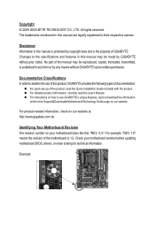
...in any form or by copyright laws and is the property of the motherboard is 1.0. For product-related information, check on our website at: http://www.gigabyte.com.tw Identifying Your Motherboard Revision The revision number on our website. All rights reserved. Example: ...notice. For example, "REV: 1.0" means the revision of GIGABYTE. No part of the product, read or download the information on/from the Support&Downloads\Motherboard\Technology Guide page on your motherboard revision before updating motherboard BIOS, drivers, or when looking for technical information. For ...
...in any form or by copyright laws and is the property of the motherboard is 1.0. For product-related information, check on our website at: http://www.gigabyte.com.tw Identifying Your Motherboard Revision The revision number on our website. All rights reserved. Example: ...notice. For example, "REV: 1.0" means the revision of GIGABYTE. No part of the product, read or download the information on/from the Support&Downloads\Motherboard\Technology Guide page on your motherboard revision before updating motherboard BIOS, drivers, or when looking for technical information. For ...
Manual
Page 4
Table of Contents Box Contents...6 Optional Items...6 GA-P55-UD3P/GA-P55-UD3R Motherboard Layout 7 Block Diagram...8 Chapter 1 Hardware Installation 9 1-1 Installation Precautions 9 1-2 Product Specifications 10 1-3 Installing the CPU and CPU Cooler 13 1-3-1 Installing the CPU 13 1-3-2 Installing the CPU ...
Table of Contents Box Contents...6 Optional Items...6 GA-P55-UD3P/GA-P55-UD3R Motherboard Layout 7 Block Diagram...8 Chapter 1 Hardware Installation 9 1-1 Installation Precautions 9 1-2 Product Specifications 10 1-3 Installing the CPU and CPU Cooler 13 1-3-1 Installing the CPU 13 1-3-2 Installing the CPU ...
Manual
Page 6
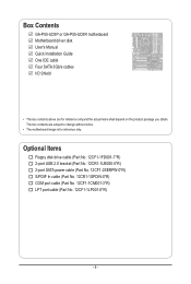
Box Contents GA-P55-UD3P or GA-P55-UD3R motherboard Motherboard driver disk User's Manual Quick Installation Guide One IDE cable Four SATA 3Gb/s cables I/O Shield • The box contents above are subject to change without notice. • The motherboard image is for reference only and the actual items shall depend on the product package you obtain. Optional Items...
Box Contents GA-P55-UD3P or GA-P55-UD3R motherboard Motherboard driver disk User's Manual Quick Installation Guide One IDE cable Four SATA 3Gb/s cables I/O Shield • The box contents above are subject to change without notice. • The motherboard image is for reference only and the actual items shall depend on the product package you obtain. Optional Items...
Manual
Page 7
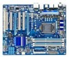
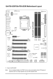
... card, use other expansion slots. - 7 - GA-P55-UD3P/GA-P55-UD3R Motherboard Layout KB_USB R_SPDIF CPU_FAN ATX_12V_2X4 USB_ESATA_2 USB_ESATA_1 LGA1156 PHASE LED ATX PWR_FAN GA-P55-UD3P / GA-P55-UD3R R_USB USB_LAN JMB362 SYS_FAN1 AUDIO F_AUDIO RTL8111D PCIEX16 PCIEX1(Note) PCI1 CODEC PCI2 PCIEX4 TPM IC j DDR3_2 DDR3_1 IDE DDR3_4 DDR3_3 GIGABYTE SATA2 GSATA2_1 GSATA2_0 Intel® P55 SYS_FAN2 CD_IN SPDIF_I SPDIF_O IT8720...
... card, use other expansion slots. - 7 - GA-P55-UD3P/GA-P55-UD3R Motherboard Layout KB_USB R_SPDIF CPU_FAN ATX_12V_2X4 USB_ESATA_2 USB_ESATA_1 LGA1156 PHASE LED ATX PWR_FAN GA-P55-UD3P / GA-P55-UD3R R_USB USB_LAN JMB362 SYS_FAN1 AUDIO F_AUDIO RTL8111D PCIEX16 PCIEX1(Note) PCI1 CODEC PCI2 PCIEX4 TPM IC j DDR3_2 DDR3_1 IDE DDR3_4 DDR3_3 GIGABYTE SATA2 GSATA2_1 GSATA2_0 Intel® P55 SYS_FAN2 CD_IN SPDIF_I SPDIF_O IT8720...
Manual
Page 9
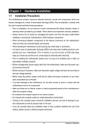
... product, please consult a certified computer technician. - 9 - If you are connected tightly and securely. • When handling the motherboard, avoid touching any installation steps or have it on top of an antistatic pad or within an electrostatic shielding container. • Before...best to wear an electrostatic discharge (ESD) wrist strap when handling electronic com- Chapter 1 Hardware Installation 1-1 Installation Precautions The motherboard contains numerous delicate electronic circuits and components which can lead to damage to system components as well as physical harm to the ...
... product, please consult a certified computer technician. - 9 - If you are connected tightly and securely. • When handling the motherboard, avoid touching any installation steps or have it on top of an antistatic pad or within an electrostatic shielding container. • Before...best to wear an electrostatic discharge (ESD) wrist strap when handling electronic com- Chapter 1 Hardware Installation 1-1 Installation Precautions The motherboard contains numerous delicate electronic circuits and components which can lead to damage to system components as well as physical harm to the ...
Manual
Page 12
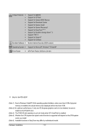
... Internet Security (OEM version) Operating System w Support for Microsoft® Windows® 7/Vista/XP Form Factor w ATX Form Factor; 30.5cm x 24.4cm j Only for GA-P55-UD3P. (Note 1) Due to Windows Vista/XP 32-bit operating system limitation, when more than 4 GB of physical memory is installed, the actual memory size... CPU/system fan speed control function is supported will depend on the CPU/system cooler you install. (Note 5) Available functions in EasyTune may differ by motherboard model. Hardware Installation - 12 -
... Internet Security (OEM version) Operating System w Support for Microsoft® Windows® 7/Vista/XP Form Factor w ATX Form Factor; 30.5cm x 24.4cm j Only for GA-P55-UD3P. (Note 1) Due to Windows Vista/XP 32-bit operating system limitation, when more than 4 GB of physical memory is installed, the actual memory size... CPU/system fan speed control function is supported will depend on the CPU/system cooler you install. (Note 5) Available functions in EasyTune may differ by motherboard model. Hardware Installation - 12 -
Manual
Page 13
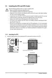
... to your hardware specifications including the CPU, graphics card, memory, hard drive, etc. 1-3-1 Installing the CPU A. Locate the alignment keys on the motherboard CPU socket and the notches on the CPU - 13 - If you may occur. • Set the CPU host frequency in accordance with the...; Apply an even and thin layer of thermal grease on the computer if the CPU cooler is not recommended that the motherboard supports the CPU. (Go to GIGABYTE's website for the peripherals. 1-3 Installing the CPU and CPU Cooler Read the following guidelines before installing the CPU to prevent...
... to your hardware specifications including the CPU, graphics card, memory, hard drive, etc. 1-3-1 Installing the CPU A. Locate the alignment keys on the motherboard CPU socket and the notches on the CPU - 13 - If you may occur. • Set the CPU host frequency in accordance with the...; Apply an even and thin layer of thermal grease on the computer if the CPU cooler is not recommended that the motherboard supports the CPU. (Go to GIGABYTE's website for the peripherals. 1-3 Installing the CPU and CPU Cooler Read the following guidelines before installing the CPU to prevent...
Manual
Page 14
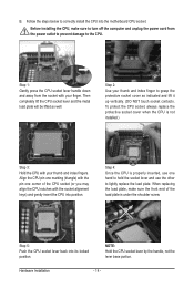
... plate will be lifted as indicated and lift it up vertically. (DO NOT touch socket contacts. Step 5: Push the CPU socket lever back into the motherboard CPU socket. Align the CPU pin one marking (triangle) with your finger. When replacing the load plate, make sure to turn off the computer and...
... plate will be lifted as indicated and lift it up vertically. (DO NOT touch socket contacts. Step 5: Push the CPU socket lever back into the motherboard CPU socket. Align the CPU pin one marking (triangle) with your finger. When replacing the load plate, make sure to turn off the computer and...

Manual
Page 15
.... If the push pin is inserted as the example cooler.) Step 1: Apply an even and thin layer of thermal grease on the motherboard. Use extreme care when removing the CPU cooler because the thermal grease/tape between the CPU cooler and CPU may damage the CPU. ...pushing down on installing the cooler.) Step 5: After the installation, check the back of the motherboard. 1-3-2 Installing the CPU Cooler Follow the steps below to correctly install the CPU cooler on the motherboard. (The following procedure uses Intel® boxed cooler as the picture above shows, the installation...
.... If the push pin is inserted as the example cooler.) Step 1: Apply an even and thin layer of thermal grease on the motherboard. Use extreme care when removing the CPU cooler because the thermal grease/tape between the CPU cooler and CPU may damage the CPU. ...pushing down on installing the cooler.) Step 5: After the installation, check the back of the motherboard. 1-3-2 Installing the CPU Cooler Follow the steps below to correctly install the CPU cooler on the motherboard. (The following procedure uses Intel® boxed cooler as the picture above shows, the installation...
Manual
Page 16
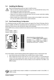
... that memory of the memory. Hardware Installation - 16 - If you begin to install the memory: • Make sure that the motherboard supports the memory. The four DDR3 memory sockets are unable to install them in the DDR3_1 or DDR3_3 sockets. When enabling Dual Channel ... to insert the memory, switch the direction. 1-4-1 Dual Channel Memory Configuration This motherboard provides four DDR3 memory sockets and supports Dual Channel Technology. DS/SS - - A memory module can be used . (Go to GIGABYTE's website for optimum performance. DS/SS Four Modules DS/SS DS/SS DS/...
... that memory of the memory. Hardware Installation - 16 - If you begin to install the memory: • Make sure that the motherboard supports the memory. The four DDR3 memory sockets are unable to install them in the DDR3_1 or DDR3_3 sockets. When enabling Dual Channel ... to insert the memory, switch the direction. 1-4-1 Dual Channel Memory Configuration This motherboard provides four DDR3 memory sockets and supports Dual Channel Technology. DS/SS - - A memory module can be used . (Go to GIGABYTE's website for optimum performance. DS/SS Four Modules DS/SS DS/SS DS/...
Manual
Page 17
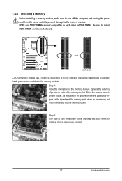
Place the memory module on this motherboard. 1-4-2 Installing a Memory Before installing a memory module, make sure to turn off the computer and unplug the power cord from the power outlet to prevent damage ...
Place the memory module on this motherboard. 1-4-2 Installing a Memory Before installing a memory module, make sure to turn off the computer and unplug the power cord from the power outlet to prevent damage ...
Manual
Page 18
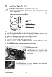
... and unplug the power cord from the chassis back panel. 2. If necessary, go to BIOS Setup to install an expansion card: • Make sure the motherboard supports the expansion card.
... and unplug the power cord from the chassis back panel. 2. If necessary, go to BIOS Setup to install an expansion card: • Make sure the motherboard supports the expansion card.
Manual
Page 19
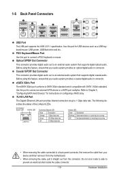
... Connector This connector provides digital audio out to prevent an electrical short inside the cable connector. - 19 - Do not rock it straight out from the motherboard. • When removing the cable, pull it side to side to an external audio system that supports digital optical audio. Optical S/PDIF Out Connector This...
... Connector This connector provides digital audio out to prevent an electrical short inside the cable connector. - 19 - Do not rock it straight out from the motherboard. • When removing the cable, pull it side to side to an external audio system that supports digital optical audio. Optical S/PDIF Out Connector This...
Manual
Page 21
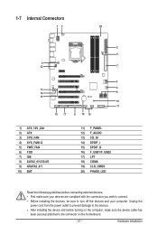
... devices and your devices are compliant with the connectors you wish to connect. • Before installing the devices, be sure to the connector on the motherboard. - 21 - Hardware Installation
... devices and your devices are compliant with the connectors you wish to connect. • Before installing the devices, be sure to the connector on the motherboard. - 21 - Hardware Installation
Manual
Page 22
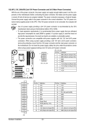
...5V (Only for 2x12-pin ATX) GND (Only for 2x12-pin ATX) - 22 - If a power supply is turned off and all the components on the motherboard. When using a power supply providing a 2x2 12V and a 2x10 power connector. 8 4 5 1 ATX_12V_2X4 ATX_12V_2X4: Pin No. Before connecting the power connector, first... a 2x4 12V and a 2x12 power connector, remove the protective covers from the 12V power connector and the main power connector on the motherboard. If the 12V power connector is recommended that a power supply that can withstand high power consumption be used that does not provide the ...
...5V (Only for 2x12-pin ATX) GND (Only for 2x12-pin ATX) - 22 - If a power supply is turned off and all the components on the motherboard. When using a power supply providing a 2x2 12V and a 2x10 power connector. 8 4 5 1 ATX_12V_2X4 ATX_12V_2X4: Pin No. Before connecting the power connector, first... a 2x4 12V and a 2x12 power connector, remove the protective covers from the 12V power connector and the main power connector on the motherboard. If the 12V power connector is recommended that a power supply that can withstand high power consumption be used that does not provide the ...
Manual
Page 23
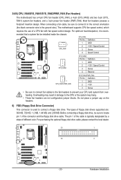
...sure to connect a floppy disk drive. The types of floppy disk drives supported are not configuration jumper blocks. 3/4/5) CPU_FAN/SYS_FAN1/SYS_FAN2/PWR_FAN (Fan Headers) The motherboard has a 4-pin CPU fan header (CPU_FAN), a 4-pin (SYS_FAN2) and two 3-pin (SYS_ FAN1) system fan headers, and a 3-pin power fan .... Overheating may hang. • These fan headers are : 360 KB, 720 KB, 1.2 MB, 1.44 MB, and 2.88 MB. The motherboard supports CPU fan speed control, which requires the use of different color. mended that a system fan be sure to connect it is used to locate...
...sure to connect a floppy disk drive. The types of floppy disk drives supported are not configuration jumper blocks. 3/4/5) CPU_FAN/SYS_FAN1/SYS_FAN2/PWR_FAN (Fan Headers) The motherboard has a 4-pin CPU fan header (CPU_FAN), a 4-pin (SYS_FAN2) and two 3-pin (SYS_ FAN1) system fan headers, and a 3-pin power fan .... Overheating may hang. • These fan headers are : 360 KB, 720 KB, 1.2 MB, 1.44 MB, and 2.88 MB. The motherboard supports CPU fan speed control, which requires the use of different color. mended that a system fan be sure to connect it is used to locate...
Manual
Page 27
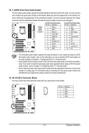
... be present on each wire instead of a single plug. Pin No. You may connect the audio cable that has separated connectors on both of the motherboard header. Definition 1 CD-L 2 GND 3 GND 1 4 CD-R - 27 - Definition 1 2 1 MIC2_L 1 MIC 2 GND 2 GND 9 10 3 MIC2_R 3 MIC Power 4 -ACZ_DET 4 NC 5 LINE2_R 5 Line Out (R) 6 GND 6 NC 7 FAUDIO_JD 7 NC...
... be present on each wire instead of a single plug. Pin No. You may connect the audio cable that has separated connectors on both of the motherboard header. Definition 1 CD-L 2 GND 3 GND 1 4 CD-R - 27 - Definition 1 2 1 MIC2_L 1 MIC 2 GND 2 GND 9 10 3 MIC2_R 3 MIC Power 4 -ACZ_DET 4 NC 5 LINE2_R 5 Line Out (R) 6 GND 6 NC 7 FAUDIO_JD 7 NC...
Manual
Page 28
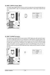
For example, some graphics cards may require you to use a S/PDIF digital audio cable for digital audio output from your motherboard to your graphics card if you wish to connect an HDMI display to the graphics card and have digital audio output from your expansion card. ... 2 SPDIFI 3 GND 1 15) SPDIF_O (S/PDIF Out Header) This header supports digital S/PDIF Out and connects a S/PDIF digital audio cable (provided by expansion cards) for your motherboard to an audio device that supports digital audio out via an optional S/PDIF In cable.
For example, some graphics cards may require you to use a S/PDIF digital audio cable for digital audio output from your motherboard to your graphics card if you wish to connect an HDMI display to the graphics card and have digital audio output from your expansion card. ... 2 SPDIFI 3 GND 1 15) SPDIF_O (S/PDIF Out Header) This header supports digital S/PDIF Out and connects a S/PDIF digital audio cable (provided by expansion cards) for your motherboard to an audio device that supports digital audio out via an optional S/PDIF In cable.


