Manual
Page 4
... ...6 GA-P35T-DS4 Motherboard Layout 7 Block Diagram ...8 Chapter 1 Hardware Installation 9 1-1 Installation Precautions 9 1-2 Product Specifications 10 1-3 Installing the CPU and CPU Cooler 13 1-3-1 Installing the CPU 13 1-3-2 Installing the CPU Cooler 15 1-4 Installing the Memory 16 1-4-1 Dual Channel Memory Configuration 16 1-4-2 Installing a Memory 17 1-5 Installing an Expansion Card 18 1-6 Installing the SATA Bracket 20 1-7 Back Panel Connectors 21 1-8 Internal Connectors 23 Chapter 2 BIOS Setup 35 2-1 Startup Screen 36 2-2 The Main Menu 37 2-3 Standard CMOS Features...
... ...6 GA-P35T-DS4 Motherboard Layout 7 Block Diagram ...8 Chapter 1 Hardware Installation 9 1-1 Installation Precautions 9 1-2 Product Specifications 10 1-3 Installing the CPU and CPU Cooler 13 1-3-1 Installing the CPU 13 1-3-2 Installing the CPU Cooler 15 1-4 Installing the Memory 16 1-4-1 Dual Channel Memory Configuration 16 1-4-2 Installing a Memory 17 1-5 Installing an Expansion Card 18 1-6 Installing the SATA Bracket 20 1-7 Back Panel Connectors 21 1-8 Internal Connectors 23 Chapter 2 BIOS Setup 35 2-1 Startup Screen 36 2-2 The Main Menu 37 2-3 Standard CMOS Features...
Manual
Page 10
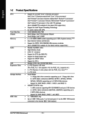
... the internal IEEE 1394 headers) GA-P35T-DS4 Motherboard - 10 - Support for SATA RAID 0, RAID 1, RAID 5, and RAID 10 Š GIGABYTE SATA2 chip: - 1 x IDE connector supporting ATA-133/100/66/33 and up to 2 IDE devices - 2 x SATA 3 Gb/s connectors (GSATAII0, GSATAII1) supporting up to 2 SATA 3Gb/s devices - TSB43AB23 chip Š Up to 3 IEEE 1394a ports (1 on the back panel, 2 via the IEEE 1394 bracket connected to GIGABYTE's website for the latest memory support list.) Š Realtek ALC889A codec Š High Definition Audio Š 2/4/5.1/7.1-channel Š Support...
... the internal IEEE 1394 headers) GA-P35T-DS4 Motherboard - 10 - Support for SATA RAID 0, RAID 1, RAID 5, and RAID 10 Š GIGABYTE SATA2 chip: - 1 x IDE connector supporting ATA-133/100/66/33 and up to 2 IDE devices - 2 x SATA 3 Gb/s connectors (GSATAII0, GSATAII1) supporting up to 2 SATA 3Gb/s devices - TSB43AB23 chip Š Up to 3 IEEE 1394a ports (1 on the back panel, 2 via the IEEE 1394 bracket connected to GIGABYTE's website for the latest memory support list.) Š Realtek ALC889A codec Š High Definition Audio Š 2/4/5.1/7.1-channel Š Support...
Manual
Page 12
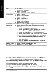
Increase FSB voltage by motherboard model. (Note 4) The adjustable CPU voltage range depends on the CPU being used. (Note 5) Due to chipset limitation, Intel ICH9R RAID driver does not support Windows 2000 operating system. Adjust DDR3 frequency - English BIOS Unique Features Bundled Software Overclocking Operating System Form Factor Š 2 x 8 Mbit flash Š Use of physical memory is installed, the actual memory size displayed will be less than 4 GB of licensed AWARD BIOS Š Support for Dual BIOSTM Š...
Increase FSB voltage by motherboard model. (Note 4) The adjustable CPU voltage range depends on the CPU being used. (Note 5) Due to chipset limitation, Intel ICH9R RAID driver does not support Windows 2000 operating system. Adjust DDR3 frequency - English BIOS Unique Features Bundled Software Overclocking Operating System Form Factor Š 2 x 8 Mbit flash Š Use of physical memory is installed, the actual memory size displayed will be less than 4 GB of licensed AWARD BIOS Š Support for Dual BIOSTM Š...
Manual
Page 16
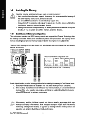
... to upgrade by allowing different memory sizes to insert the memory, switch the direction. 1-4-1 Dual Channel Memory Configuration This motherboard provides four DDR3 memory sockets and supports Dual Channel Technology. If you begin to prevent hardware damage. • Memory modules have a foolproof design. GA-P35T-DS4 Motherboard - 16 - The four DDR3 memory sockets are unable to be used and installed in only one DDR3 memory module is operating in Flex Memory Mode will appear during the POST. English 1-4 Installing the Memory...
... to upgrade by allowing different memory sizes to insert the memory, switch the direction. 1-4-1 Dual Channel Memory Configuration This motherboard provides four DDR3 memory sockets and supports Dual Channel Technology. If you begin to prevent hardware damage. • Memory modules have a foolproof design. GA-P35T-DS4 Motherboard - 16 - The four DDR3 memory sockets are unable to be used and installed in only one DDR3 memory module is operating in Flex Memory Mode will appear during the POST. English 1-4 Installing the Memory...
Manual
Page 18
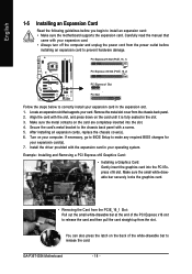
... the graphics card into the slot. 4. GA-P35T-DS4 Motherboard - 18 - Carefully read the manual that supports your expansion card. • Always turn off the computer and unplug the power cord from the power outlet before you begin to install an expansion card: • Make sure the motherboard supports the expansion card. If necessary, go to BIOS Setup to release the card and then pull the card straight up from the chassis back panel...
... the graphics card into the slot. 4. GA-P35T-DS4 Motherboard - 18 - Carefully read the manual that supports your expansion card. • Always turn off the computer and unplug the power cord from the power outlet before you begin to install an expansion card: • Make sure the motherboard supports the expansion card. If necessary, go to BIOS Setup to release the card and then pull the card straight up from the chassis back panel...

Manual
Page 25
.... A red power connector wire indicates a positive connection and requires a +12V voltage. The motherboard supports CPU fan speed control, which requires the use of a CPU fan with colorcoded power connector wires. Overheating may result in damage to this header. Hardware Installation Definition 1 GND 2 +12V 3 Sense 6) NB_FAN (North Bridge Fan Header) Connect the North Bridge fan cable to the CPU/North Bridge or the system may hang. • These fan headers are designed with color-coded power connector wires. Most fans are not configuration jumper blocks...
.... A red power connector wire indicates a positive connection and requires a +12V voltage. The motherboard supports CPU fan speed control, which requires the use of a CPU fan with colorcoded power connector wires. Overheating may result in damage to this header. Hardware Installation Definition 1 GND 2 +12V 3 Sense 6) NB_FAN (North Bridge Fan Header) Connect the North Bridge fan cable to the CPU/North Bridge or the system may hang. • These fan headers are designed with color-coded power connector wires. Most fans are not configuration jumper blocks...

Manual
Page 32
... BIOS configurations) and reset the CMOS values to USB 2.0/1.1 specification. GA-P35T-DS4 Motherboard - 32 - For purchasing the optional USB bracket, please contact the local dealer. 10 9 21 Pin No. 1 2 3 4 5 6 7 8 9 10 Definition Power (5V) Power (5V) USB DXUSB DYUSB DX+ USB DY+ GND GND No Pin NC • Do not plug the IEEE 1394 bracket (2x5-pin) cable into the USB header. • Prior to installing the USB bracket, be sure to clear the CMOS values (e.g. To clear...
... BIOS configurations) and reset the CMOS values to USB 2.0/1.1 specification. GA-P35T-DS4 Motherboard - 32 - For purchasing the optional USB bracket, please contact the local dealer. 10 9 21 Pin No. 1 2 3 4 5 6 7 8 9 10 Definition Power (5V) Power (5V) USB DXUSB DYUSB DX+ USB DY+ GND GND No Pin NC • Do not plug the IEEE 1394 bracket (2x5-pin) cable into the USB header. • Prior to installing the USB bracket, be sure to clear the CMOS values (e.g. To clear...

Manual
Page 41
Options are: Floppy, LS120, Hard Disk, CDROM, ZIP, USB-FDD, USB-ZIP, USB-CDROM, USB-HDD, Legacy LAN, Disabled. Capability Enables or disables the S.M.A.R.T. (Self Monitoring and Reporting Technology) capability of your system to report read/write errors of loading the operating system from the available devices. This feature only works for operating systems that supports this feature. BIOS Setup Use the up or down arrow key to select a device and press to exit this item, set the...
Options are: Floppy, LS120, Hard Disk, CDROM, ZIP, USB-FDD, USB-ZIP, USB-CDROM, USB-HDD, Legacy LAN, Disabled. Capability Enables or disables the S.M.A.R.T. (Self Monitoring and Reporting Technology) capability of your system to report read/write errors of loading the operating system from the available devices. This feature only works for operating systems that supports this feature. BIOS Setup Use the up or down arrow key to select a device and press to exit this item, set the...
Manual
Page 42
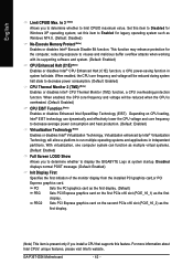
... Memory Protect (Note) Enables or disables Intel® Execute Disable Bit function. Depending on the second PCIe x16 slot (PCIE_16_2) as multiple virtual systems. (Default: Enabled) Full Screen LOGO Show Allows you to determine whether to display the GIGABYTE Logo at system startup. With virtualization, one computer system can dynamically and effectively lower the CPU voltage and core frequency to Disabled for legacy operating system such as the first display. PEG2 Sets PCI Express graphics card...
... Memory Protect (Note) Enables or disables Intel® Execute Disable Bit function. Depending on the second PCIe x16 slot (PCIE_16_2) as multiple virtual systems. (Default: Enabled) Full Screen LOGO Show Allows you to determine whether to display the GIGABYTE Logo at system startup. With virtualization, one computer system can dynamically and effectively lower the CPU voltage and core frequency to Disabled for legacy operating system such as the first display. PEG2 Sets PCI Express graphics card...

Manual
Page 43
...2-5 Integrated Peripherals CMOS Setup Utility-Copyright (C) 1984-2007 Award Software Integrated Peripherals SATA RAID/AHCI Mode SATA Port0-3 Native Mode USB Controller USB 2.0 Controller USB Keyboard Support USB Mouse Support Legacy USB storage detect Azalia Codec Onboard H/W 1394 Onboard H/W LAN ` SMART LAN Onboard LAN Boot ROM Onboard SATA/IDE Device Onboard SATA/IDE Ctrl Mode Onboard Serial Port 1 Onboard Parallel Port Parallel Port Mode [Disabled] [Disabled] [Enabled] [Enabled] [Disabled] [Disabled] [Enabled] [Auto] [Enabled] [Enabled] [Press Enter] [Disabled] [Enabled] [IDE] [3F8/IRQ4...
...2-5 Integrated Peripherals CMOS Setup Utility-Copyright (C) 1984-2007 Award Software Integrated Peripherals SATA RAID/AHCI Mode SATA Port0-3 Native Mode USB Controller USB 2.0 Controller USB Keyboard Support USB Mouse Support Legacy USB storage detect Azalia Codec Onboard H/W 1394 Onboard H/W LAN ` SMART LAN Onboard LAN Boot ROM Onboard SATA/IDE Device Onboard SATA/IDE Ctrl Mode Onboard Serial Port 1 Onboard Parallel Port Parallel Port Mode [Disabled] [Disabled] [Enabled] [Enabled] [Disabled] [Disabled] [Enabled] [Auto] [Enabled] [Enabled] [Press Enter] [Disabled] [Enabled] [IDE] [3F8/IRQ4...

Manual
Page 44
... on the LAN cable connected to a Gigabit hub or a 10/100 Mbps hub, the following information for diagnosing your LAN cable: When No LAN Cable Is Attached... SMART LAN (LAN Cable Diagnostic Function) CMOS Setup Utility-Copyright (C) 1984-2007 Award Software SMART LAN Start detecting at Port..... GA-P35T-DS4 Motherboard - 44 - Onboard H/W 1394 Enables or disables the onboard 1394 function. (Default: Enabled) Onboard H/W LAN Enables or disables the onboard LAN function. (Default: Enabled) If you wish to install a 3rd party add-in audio card instead of using the onboard LAN, set this...
... on the LAN cable connected to a Gigabit hub or a 10/100 Mbps hub, the following information for diagnosing your LAN cable: When No LAN Cable Is Attached... SMART LAN (LAN Cable Diagnostic Function) CMOS Setup Utility-Copyright (C) 1984-2007 Award Software SMART LAN Start detecting at Port..... GA-P35T-DS4 Motherboard - 44 - Onboard H/W 1394 Enables or disables the onboard 1394 function. (Default: Enabled) Onboard H/W LAN Enables or disables the onboard LAN function. (Default: Enabled) If you wish to install a 3rd party add-in audio card instead of using the onboard LAN, set this...

Manual
Page 45
... SATA2 Chip) Enables or disables the IDE and SATA controllers integrated in Windows mode or when the LAN Boot ROM is activated. Advanced Host Controller Interface (AHCI) is the approximate length of the attached LAN cable. BIOS Setup If a cable problem occurs on Pair 1-2. IDE Configures the SATA controller to PATA mode. (Default) AHCI Configures the SATA controller to the fault or short. Onboard Parallel Port Enables or disables the onboard parallel port (LPT) and specifies its base I /O address and corresponding interrupt. When a Cable Problem Occurs... Options are...
... SATA2 Chip) Enables or disables the IDE and SATA controllers integrated in Windows mode or when the LAN Boot ROM is activated. Advanced Host Controller Interface (AHCI) is the approximate length of the attached LAN cable. BIOS Setup If a cable problem occurs on Pair 1-2. IDE Configures the SATA controller to PATA mode. (Default) AHCI Configures the SATA controller to the fault or short. Onboard Parallel Port Enables or disables the onboard parallel port (LPT) and specifies its base I /O address and corresponding interrupt. When a Cable Problem Occurs... Options are...

Manual
Page 51
..., or clear the CMOS values to reset the board to default values. (Default: Disabled) (Note) This item appears only if you install a CPU that you to be configurable. English 2-9 MB Intelligent Tweaker(M.I.T.) CMOS Setup Utility-Copyright (C) 1984-2007 Award Software MB Intelligent Tweaker(M.I.T.) Robust Graphics Booster CPU Clock Ratio (Note) CPU Host Clock Control x CPU Host Frequency (Mhz) PCI Express Frequency (Mhz) C.I.A. 2 System Memory Multiplier (SPD) Memory Frequency (Mhz) 800 High Speed DRAM DLL Settings ******** System Voltage Optimized System Voltage Control DDR3 OverVoltage...
..., or clear the CMOS values to reset the board to default values. (Default: Disabled) (Note) This item appears only if you install a CPU that you to be configurable. English 2-9 MB Intelligent Tweaker(M.I.T.) CMOS Setup Utility-Copyright (C) 1984-2007 Award Software MB Intelligent Tweaker(M.I.T.) Robust Graphics Booster CPU Clock Ratio (Note) CPU Host Clock Control x CPU Host Frequency (Mhz) PCI Express Frequency (Mhz) C.I.A. 2 System Memory Multiplier (SPD) Memory Frequency (Mhz) 800 High Speed DRAM DLL Settings ******** System Voltage Optimized System Voltage Control DDR3 OverVoltage...

Manual
Page 73
... • Motherboard driver disk. 5-1-1 Configuring Intel® ICH9R SATA Controllers A. B. Make a floppy disk containing the SATA RAID/AHCI driver. (Note 2) E. Installing SATA hard drive(s) in RAID BIOS. (Note 1) D. Install the SATA RAID/AHCI driver and operating system. (Note 2) Before you begin Please prepare: • At least two SATA hard drives (to ensure optimal performance, it is set to AHCI or RAID mode. (Note 3) Due to available SATA port on the SATA controller. (Note 2) Required when the SATA controller is recommended that you use two hard drives with identical model and...
... • Motherboard driver disk. 5-1-1 Configuring Intel® ICH9R SATA Controllers A. B. Make a floppy disk containing the SATA RAID/AHCI driver. (Note 2) E. Installing SATA hard drive(s) in RAID BIOS. (Note 1) D. Install the SATA RAID/AHCI driver and operating system. (Note 2) Before you begin Please prepare: • At least two SATA hard drives (to ensure optimal performance, it is set to AHCI or RAID mode. (Note 3) Due to available SATA port on the SATA controller. (Note 2) Required when the SATA controller is recommended that you use two hard drives with identical model and...

Manual
Page 79
... hard drive. Appendix In BIOS Setup, go to available SATA port on the motherboard you will see shall depend on the motherboard. The BIOS Setup menus described in this section may differ from your motherboard, refer to "Chapter 1," Hardware Installation," to RAID/IDE (Figure 1). CMOS Setup Utility-Copyright (C) 1984-2007 Award Software Integrated Peripherals SATA RAID/AHCI Mode SATA Port0-3 Native Mode USB Controller USB 2.0 Controller USB Keyboard Support USB Mouse Support Legacy USB storage detect Azalia Codec Onboard H/W 1394 Onboard H/W LAN ` SMART LAN Onboard LAN Boot ROM...
... hard drive. Appendix In BIOS Setup, go to available SATA port on the motherboard you will see shall depend on the motherboard. The BIOS Setup menus described in this section may differ from your motherboard, refer to "Chapter 1," Hardware Installation," to RAID/IDE (Figure 1). CMOS Setup Utility-Copyright (C) 1984-2007 Award Software Integrated Peripherals SATA RAID/AHCI Mode SATA Port0-3 Native Mode USB Controller USB 2.0 Controller USB Keyboard Support USB Mouse Support Legacy USB storage detect Azalia Codec Onboard H/W 1394 Onboard H/W LAN ` SMART LAN Onboard LAN Boot ROM...

Manual
Page 80
... the installation of the GIGABYTE SATA2 RAID BIOS utility (Figure 3), use the up or down arrow key to highlight through choices in RAID BIOS Enter the RAID BIOS setup utility to configure a RAID array. GIGABYTE Technology Corp. PCIE-to enter the GIGABYTE SATA2 RAID BIOS utility. Highlight the item that you can select a hard drive in the Hard Disk Drive List block and press to enter RAID Setup Utility" (Figure 2). GA-P35T-DS4 Motherboard - 80 - After the POST memory test begins and before the operating system boot begins, look for a non-RAID configuration...
... the installation of the GIGABYTE SATA2 RAID BIOS utility (Figure 3), use the up or down arrow key to highlight through choices in RAID BIOS Enter the RAID BIOS setup utility to configure a RAID array. GIGABYTE Technology Corp. PCIE-to enter the GIGABYTE SATA2 RAID BIOS utility. Highlight the item that you can select a hard drive in the Hard Disk Drive List block and press to enter RAID Setup Utility" (Figure 2). GA-P35T-DS4 Motherboard - 80 - After the POST memory test begins and before the operating system boot begins, look for a non-RAID configuration...

Manual
Page 85
... is/are configured to RAID/AHCI mode, you need to install the SATA controller driver during the Windows setup process. Once at the A:\> prompt, change to the floppy disk. Press to copy the driver in your optical drive (example: D:\>). See the instructions below about how to exit when finished. (Note) Figure 1 Figure 2 For users without a startup disk: Use an alternative system and insert the motherboard driver disk. At the D:\> prompt, type the following...
... is/are configured to RAID/AHCI mode, you need to install the SATA controller driver during the Windows setup process. Once at the A:\> prompt, change to the floppy disk. Press to copy the driver in your optical drive (example: D:\>). See the instructions below about how to exit when finished. (Note) Figure 1 Figure 2 For users without a startup disk: Use an alternative system and insert the motherboard driver disk. At the D:\> prompt, type the following...

Manual
Page 86
... type of Windows XP installation. S=Specify Additional Device ENTER=Continue F3=Exit Figure 2 GA-P35T-DS4 Motherboard - 86 - Windows Setup Press F6 if you do not have a device support disk from the Windows Vista/XP/2000 setup disk and press as soon as you see the message "Press F6 if you see the next screen. The following mass storage devices(s) * To specify additional SCSI adapters, CD-ROM drives, or special disk controllers for use with Windows...
... type of Windows XP installation. S=Specify Additional Device ENTER=Continue F3=Exit Figure 2 GA-P35T-DS4 Motherboard - 86 - Windows Setup Press F6 if you do not have a device support disk from the Windows Vista/XP/2000 setup disk and press as soon as you see the message "Press F6 if you see the next screen. The following mass storage devices(s) * To specify additional SCSI adapters, CD-ROM drives, or special disk controllers for use with Windows...

Manual
Page 95
... be used at the same time. Double-click the icon to the Mic in jack (pink) on the back panel or the Line in jack on the front panel and back panel cannot be output from the S/PDIF OUT. 5-2-3 Configuring Microphone Recording Step 1: After installing the audio driver, the Audio Manager icon will appear in your microphone to access the Audio Control Panel...
... be used at the same time. Double-click the icon to the Mic in jack (pink) on the back panel or the Line in jack on the front panel and back panel cannot be output from the S/PDIF OUT. 5-2-3 Configuring Microphone Recording Step 1: After installing the audio driver, the Audio Manager icon will appear in your microphone to access the Audio Control Panel...
Manual
Page 98
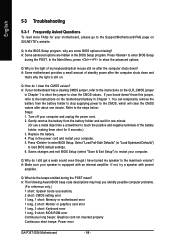
... motherboard, please go to clear the CMOS values. Plug in Chapter 1 to short the jumper to the Support\Motherboard\FAQ page on . A: The following Award BIOS beep code descriptions may help you identify possible computer problems. (For reference only.) 1 short: System boots successfully 2 short: CMOS setting error 1 long, 1 short: Memory or motherboard error 1 long, 2 short: Monitor or graphics card error 1 long, 3 short: Keyboard error 1 long, 9 short: BIOS ROM error Continuous long beeps: Graphics card not inserted properly Continuous short beeps: Power error GA-P35T-DS4 Motherboard...
... motherboard, please go to clear the CMOS values. Plug in Chapter 1 to short the jumper to the Support\Motherboard\FAQ page on . A: The following Award BIOS beep code descriptions may help you identify possible computer problems. (For reference only.) 1 short: System boots successfully 2 short: CMOS setting error 1 long, 1 short: Memory or motherboard error 1 long, 2 short: Monitor or graphics card error 1 long, 3 short: Keyboard error 1 long, 9 short: BIOS ROM error Continuous long beeps: Graphics card not inserted properly Continuous short beeps: Power error GA-P35T-DS4 Motherboard...


