Manual
Page 1
GA-P35-DS3R/ GA-P35-DS3/ GA-P35-S3 LGA775 socket motherboard for Intel® CoreTM processor family/ Intel® Pentium® processor family/Intel® Celeron® processor family User's Manual Rev. 2002 12ME-P35DS3R-2002R
GA-P35-DS3R/ GA-P35-DS3/ GA-P35-S3 LGA775 socket motherboard for Intel® CoreTM processor family/ Intel® Pentium® processor family/Intel® Celeron® processor family User's Manual Rev. 2002 12ME-P35DS3R-2002R
Manual
Page 2
Motherboard GA-P35-DS3R/GA-P35-DS3/GA-P35-S3 Jul. 25, 2007 Motherboard GA-P35-DS3R/GA-P35-DS3/ GA-P35-S3 Jul. 25, 2007
Motherboard GA-P35-DS3R/GA-P35-DS3/GA-P35-S3 Jul. 25, 2007 Motherboard GA-P35-DS3R/GA-P35-DS3/ GA-P35-S3 Jul. 25, 2007
Manual
Page 3
... features, read or download the information on/from the Support\Motherboard\Technology Guide page on your motherboard revision before updating motherboard BIOS, drivers, or when looking for technical information. Check your motherboard looks like this manual may be made by GIGABYTE without GIGABYTE's prior written permission. Copyright © 2007 GIGA-BYTE TECHNOLOGY CO., LTD. No part...
... features, read or download the information on/from the Support\Motherboard\Technology Guide page on your motherboard revision before updating motherboard BIOS, drivers, or when looking for technical information. Check your motherboard looks like this manual may be made by GIGABYTE without GIGABYTE's prior written permission. Copyright © 2007 GIGA-BYTE TECHNOLOGY CO., LTD. No part...
Manual
Page 4
Table of Contents OptionalItems ...6 Box Contents ...6 GA-P35-DS3R/DS3/S3 Motherboard Layout 7 Block Diagram ...8 Chapter 1 Hardware Installation 9 1-1 Installation Precautions 9 1-2 Product Specifications 10 1-3 Installing the CPU and CPU Cooler 13 1-3-1 Installing the CPU 13 1-3-2 Installing the CPU ...
Table of Contents OptionalItems ...6 Box Contents ...6 GA-P35-DS3R/DS3/S3 Motherboard Layout 7 Block Diagram ...8 Chapter 1 Hardware Installation 9 1-1 Installation Precautions 9 1-2 Product Specifications 10 1-3 Installing the CPU and CPU Cooler 13 1-3-1 Installing the CPU 13 1-3-2 Installing the CPU ...
Manual
Page 6
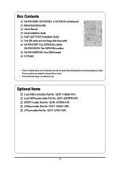
... only. Box Contents GA-P35-DS3R, GA-P35-DS3, or GA-P35-S3 motherboard Motherboard driver disk User's Manual Quick Installation Guide Intel® LGA775 CPU Installation Guide One IDE cable and one floppy disk drive cable GA-P35-DS3R: Four SATA 3Gb/s cables GA-P35-DS3/S3: Two SATA 3Gb/s cables GA-P35-DS3R/DS3: One SATA ...bracket I/O Shield • The box contents above are subject to change without notice. • The motherboard image is for reference only and...
... only. Box Contents GA-P35-DS3R, GA-P35-DS3, or GA-P35-S3 motherboard Motherboard driver disk User's Manual Quick Installation Guide Intel® LGA775 CPU Installation Guide One IDE cable and one floppy disk drive cable GA-P35-DS3R: Four SATA 3Gb/s cables GA-P35-DS3/S3: Two SATA 3Gb/s cables GA-P35-DS3R/DS3: One SATA ...bracket I/O Shield • The box contents above are subject to change without notice. • The motherboard image is for reference only and...
Manual
Page 7
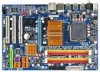
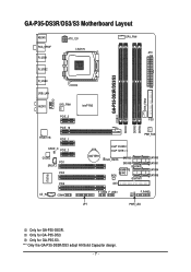
.../S3 Motherboard Layout KB_MS RCA_SPDIF R_USB1 R_USB2 R_USB3 ATX_12V LGA775 CPU_FAN ATX GA-P35-DS3R/DS3/S3 DDRII1 USB_LAN F_AUDIO AUDIO SYS_FAN1 PCIE_3 PCIE_16 RTL8111B PCIE_1 SPDIF_O PCIE_2 CODEC PCI1 SPDIF_I PCI2 IT8718 CD_IN PCI3 COMA Intel® P35 FDD DDRII3 DDRII4 DDRII2 PWR_FAN BATTERY Intel® ICH9R Intel® ICH9 CLR_CMOS SATAII2 SATAII3 GSATAII0 GIGABYTE...
.../S3 Motherboard Layout KB_MS RCA_SPDIF R_USB1 R_USB2 R_USB3 ATX_12V LGA775 CPU_FAN ATX GA-P35-DS3R/DS3/S3 DDRII1 USB_LAN F_AUDIO AUDIO SYS_FAN1 PCIE_3 PCIE_16 RTL8111B PCIE_1 SPDIF_O PCIE_2 CODEC PCI1 SPDIF_I PCI2 IT8718 CD_IN PCI3 COMA Intel® P35 FDD DDRII3 DDRII4 DDRII2 PWR_FAN BATTERY Intel® ICH9R Intel® ICH9 CLR_CMOS SATAII2 SATAII3 GSATAII0 GIGABYTE...
Manual
Page 9
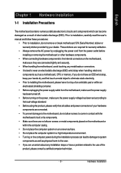
...been turned off. • Before turning on the power, make sure they are connected tightly and securely. • When handling the motherboard, avoid touching any installation steps or have it on top of an antistatic pad or within the computer casing. • Do not... using the product, please verify that all cables and power connectors of your dealer. English Chapter 1 Hardware Installation 1-1 Installation Precautions The motherboard contains numerous delicate electronic circuits and components which can lead to damage to system components as well as physical harm to the user. &#...
...been turned off. • Before turning on the power, make sure they are connected tightly and securely. • When handling the motherboard, avoid touching any installation steps or have it on top of an antistatic pad or within the computer casing. • Do not... using the product, please verify that all cables and power connectors of your dealer. English Chapter 1 Hardware Installation 1-1 Installation Precautions The motherboard contains numerous delicate electronic circuits and components which can lead to damage to system components as well as physical harm to the user. &#...
Manual
Page 10
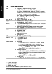
... SATA 3Gb/s devices - Only for GA-P35-S3. Only for GA-P35-DS3. "*" Only the GA-P35-DS3R/DS3 adopt All-Solid Capacitor design. Support for SATA RAID 0, RAID 1, RAID 5, and RAID 10 Š GIGABYTE SATA2 chip: - 1 x IDE ...connector supporting ATA-133/100/66/33 and up to 2 IDE devices - 2 x SATA 3Gb/s connectors (GSATAII0, GSATAII1) supporting up to 4 SATA 3Gb/s devices(Note 2) - GA-P35-DS3R/DS3/S3 Motherboard...
... SATA 3Gb/s devices - Only for GA-P35-S3. Only for GA-P35-DS3. "*" Only the GA-P35-DS3R/DS3 adopt All-Solid Capacitor design. Support for SATA RAID 0, RAID 1, RAID 5, and RAID 10 Š GIGABYTE SATA2 chip: - 1 x IDE ...connector supporting ATA-133/100/66/33 and up to 2 IDE devices - 2 x SATA 3Gb/s connectors (GSATAII0, GSATAII1) supporting up to 4 SATA 3Gb/s devices(Note 2) - GA-P35-DS3R/DS3/S3 Motherboard...
Manual
Page 12
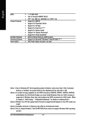
GA-P35-DS3R/DS3/S3 Motherboard - 12 - English BIOS Unique Features Bundled Software Operating System Form Factor Š 1 x 8 Mbit flash Š Use of licensed AWARD BIOS Š PnP 1.0a, DMI 2.0, SM ... 3) Whether the CPU fan speed control function is supported will depend on the CPU cooler you install. (Note 4) Available functions in Easytune may differ by motherboard model. (Note 5) Due to chipset limitation, Intel ICH9R RAID driver does not support Windows 2000 operating system.
GA-P35-DS3R/DS3/S3 Motherboard - 12 - English BIOS Unique Features Bundled Software Operating System Form Factor Š 1 x 8 Mbit flash Š Use of licensed AWARD BIOS Š PnP 1.0a, DMI 2.0, SM ... 3) Whether the CPU fan speed control function is supported will depend on the CPU cooler you install. (Note 4) Available functions in Easytune may differ by motherboard model. (Note 5) Due to chipset limitation, Intel ICH9R RAID driver does not support Windows 2000 operating system.
Manual
Page 13
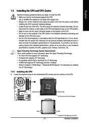
... Technology • A BIOS that the motherboard supports the CPU. (Go to GIGABYTE's website for the latest CPU support list.) • Always turn on the CPU. LGA775 CPU Socket Alignment Key LGA 775 CPU Alignment Key Pin One Corner of the CPU. Locate the alignment keys on the motherboard CPU socket and the notches...
... Technology • A BIOS that the motherboard supports the CPU. (Go to GIGABYTE's website for the latest CPU support list.) • Always turn on the CPU. LGA775 CPU Socket Alignment Key LGA 775 CPU Alignment Key Pin One Corner of the CPU. Locate the alignment keys on the motherboard CPU socket and the notches...
Manual
Page 14
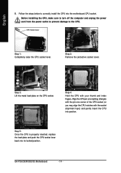
... notches with your thumb and index fingers. Follow the steps below to the CPU. CPU Socket Lever Step 1: Completely raise the CPU socket lever. GA-P35-DS3R/DS3/S3 Motherboard - 14 - Step 4: Hold the CPU with the socket alignment keys) and gently insert the CPU into position. Before installing the CPU, make sure to... plate on the CPU socket. Step 5: Once the CPU is properly inserted, replace the load plate and push the CPU socket lever back into the motherboard CPU socket.
... notches with your thumb and index fingers. Follow the steps below to the CPU. CPU Socket Lever Step 1: Completely raise the CPU socket lever. GA-P35-DS3R/DS3/S3 Motherboard - 14 - Step 4: Hold the CPU with the socket alignment keys) and gently insert the CPU into position. Before installing the CPU, make sure to... plate on the CPU socket. Step 5: Once the CPU is properly inserted, replace the load plate and push the CPU socket lever back into the motherboard CPU socket.

Manual
Page 15
... the CPU Cooler Follow the steps below to correctly install the CPU cooler on the motherboard. (The following procedure uses Intel® boxed cooler as the picture above, the ... of the arrow sign on the male push pin. (Turning the push pin along the direction of the motherboard. If the push pin is inserted as the example cooler.) Step 1: Apply an even and thin layer ...of thermal grease on the surface of the CPU cooler to the CPU fan header (CPU_FAN) on the motherboard. Use extreme care when removing the CPU cooler because the thermal grease/tape between the CPU cooler and CPU ...
... the CPU Cooler Follow the steps below to correctly install the CPU cooler on the motherboard. (The following procedure uses Intel® boxed cooler as the picture above, the ... of the arrow sign on the male push pin. (Turning the push pin along the direction of the motherboard. If the push pin is inserted as the example cooler.) Step 1: Apply an even and thin layer ...of thermal grease on the surface of the CPU cooler to the CPU fan header (CPU_FAN) on the motherboard. Use extreme care when removing the CPU cooler because the thermal grease/tape between the CPU cooler and CPU ...
Manual
Page 16
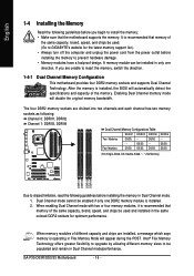
... turn off the computer and unplug the power cord from the power outlet before installing the memory to GIGABYTE's website for optimum performance. Dual Channel mode cannot be installed in Dual Channel mode/performance. DS/SS... guidelines before you are unable to insert the memory, switch the direction. 1-4-1 Dual Channel Memory Configuration This motherboard provides four DDR2 memory sockets and supports Dual Channel Technology. It is installed. 2. After the memory is ... is installed, the BIOS will double the original memory bandwidth. GA-P35-DS3R/DS3/S3 Motherboard - 16 -
... turn off the computer and unplug the power cord from the power outlet before installing the memory to GIGABYTE's website for optimum performance. Dual Channel mode cannot be installed in Dual Channel mode/performance. DS/SS... guidelines before you are unable to insert the memory, switch the direction. 1-4-1 Dual Channel Memory Configuration This motherboard provides four DDR2 memory sockets and supports Dual Channel Technology. It is installed. 2. After the memory is ... is installed, the BIOS will double the original memory bandwidth. GA-P35-DS3R/DS3/S3 Motherboard - 16 -
Manual
Page 17
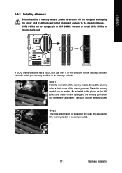
... and unplug the power cord from the power outlet to prevent damage to install DDR2 DIMMs on the socket. Place the memory module on this motherboard.
... and unplug the power cord from the power outlet to prevent damage to install DDR2 DIMMs on the socket. Place the memory module on this motherboard.
Manual
Page 18
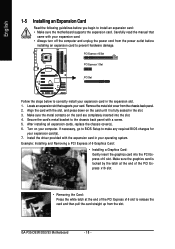
... hardware damage. Remove the metal slot cover from the power outlet before you begin to install an expansion card: • Make sure the motherboard supports the expansion card. Align the card with your card. Secure the card's metal bracket to release the card and then pull the card... manual that supports your expansion card. • Always turn off the computer and unplug the power cord from the chassis back panel. 2. GA-P35-DS3R/DS3/S3 Motherboard - 18 - PCI Express x16 Slot PCI Express x1 Slot PCI Slot Follow the steps below to make any required BIOS changes for your ...
... hardware damage. Remove the metal slot cover from the power outlet before you begin to install an expansion card: • Make sure the motherboard supports the expansion card. Align the card with your card. Secure the card's metal bracket to release the card and then pull the card... manual that supports your expansion card. • Always turn off the computer and unplug the power cord from the chassis back panel. 2. GA-P35-DS3R/DS3/S3 Motherboard - 18 - PCI Express x16 Slot PCI Express x1 Slot PCI Slot Follow the steps below to make any required BIOS changes for your ...
Manual
Page 19
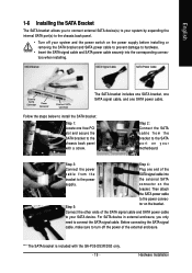
...from the SATA signal cable into the corresponding connectors when installing. Then attach the SATA power cable to the chassis back panel with the GA-P35-DS3R/DS3 only. - 19 - For SATA device in external enclosure, you to connect external SATA device(s) to your system by expanding the ...Connect the other ends of the external enclosure. Step 5: tor on the bracket. Before connecting the SATA signal cable, make sure to your motherboard. Step 3: Step 4: Connect the power Plug one free PCI slot and secure the SATA bracket to the power connec- SATA Bracket SATA ...
...from the SATA signal cable into the corresponding connectors when installing. Then attach the SATA power cable to the chassis back panel with the GA-P35-DS3R/DS3 only. - 19 - For SATA device in external enclosure, you to connect external SATA device(s) to your system by expanding the ...Connect the other ends of the external enclosure. Step 5: tor on the bracket. Before connecting the SATA signal cable, make sure to your motherboard. Step 3: Step 4: Connect the power Plug one free PCI slot and secure the SATA bracket to the power connec- SATA Bracket SATA ...
Manual
Page 20
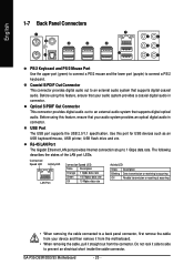
... in connector. The following describes the states of the LAN port LEDs. Use this feature, ensure that your device and then remove it from the motherboard. • When removing the cable, pull it side to side to 1 Gbps data rate. USB Port The USB port supports the USB 2.0/1.1 specification. RJ-45... This connector provides digital audio out to a back panel connector, first remove the cable from your audio system provides an optical digital audio in connector. GA-P35-DS3R/DS3/S3 Motherboard - 20 -
... in connector. The following describes the states of the LAN port LEDs. Use this feature, ensure that your device and then remove it from the motherboard. • When removing the cable, pull it side to side to 1 Gbps data rate. USB Port The USB port supports the USB 2.0/1.1 specification. RJ-45... This connector provides digital audio out to a back panel connector, first remove the cable from your audio system provides an optical digital audio in connector. GA-P35-DS3R/DS3/S3 Motherboard - 20 -
Manual
Page 22
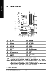
GA-P35-DS3R/DS3/S3 Motherboard - 22 - English 1-8 Internal Connectors 1 3 2 7 14 4 5 6 12 21 17 9 16 10 8 15 19 20 18 22 11 13 1) ATX_12V 2) ATX 3) CPU_FAN 4) SYS_FAN1 5) SYS_FAN2 6) PWR_FAN 7) FDD 8) IDE1 9) ...) CD_IN 16) SPDIF_I 17) SPDIF_O 18) F_USB1/F_USB2 19) COMA 20) LPT 21) CLR_CMOS 22) CI Read the following guidelines before turning on the motherboard. Only for GA-P35-DS3R. Unplug the power cord from the power outlet to prevent damage to the devices. • After installing the device and before connecting external devices...
GA-P35-DS3R/DS3/S3 Motherboard - 22 - English 1-8 Internal Connectors 1 3 2 7 14 4 5 6 12 21 17 9 16 10 8 15 19 20 18 22 11 13 1) ATX_12V 2) ATX 3) CPU_FAN 4) SYS_FAN1 5) SYS_FAN2 6) PWR_FAN 7) FDD 8) IDE1 9) ...) CD_IN 16) SPDIF_I 17) SPDIF_O 18) F_USB1/F_USB2 19) COMA 20) LPT 21) CLR_CMOS 22) CI Read the following guidelines before turning on the motherboard. Only for GA-P35-DS3R. Unplug the power cord from the power outlet to prevent damage to the devices. • After installing the device and before connecting external devices...

Manual
Page 23
Before connecting the power connector, first make sure the power supply is turned off and all the components on the motherboard. The power connector possesses a foolproof design. Do not insert the power supply cable into pins under the protective cover when using a 2x12 power ...supply, remove the protective cover from the main power connector on the motherboard. If the 12V power connector is not connected, the computer will not start. • To meet expansion requirements, it is compatible with power ...
Before connecting the power connector, first make sure the power supply is turned off and all the components on the motherboard. The power connector possesses a foolproof design. Do not insert the power supply cable into pins under the protective cover when using a 2x12 power ...supply, remove the protective cover from the main power connector on the motherboard. If the 12V power connector is not connected, the computer will not start. • To meet expansion requirements, it is compatible with power ...
Manual
Page 24
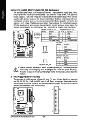
...). A red power connector wire indicates a positive connection and requires a +12V voltage. CPU_FAN (For PCB rev. 2.0): Pin No. The types of different color. 34 33 GA-P35-DS3R/DS3/S3 Motherboard 2 1 - 24 - Definition 1 1 2 CPU_FAN 3 GND Speed Control Sense 1 GND 2 +12V 3 Sense 4 +5V / Speed Control 4 +5V / Speed Control ... typically designated by a stripe of floppy disk drives supported are designed with fan speed control design. The motherboard supports CPU fan speed control, which requires the use of the connector and the floppy disk drive cable.
...). A red power connector wire indicates a positive connection and requires a +12V voltage. CPU_FAN (For PCB rev. 2.0): Pin No. The types of different color. 34 33 GA-P35-DS3R/DS3/S3 Motherboard 2 1 - 24 - Definition 1 1 2 CPU_FAN 3 GND Speed Control Sense 1 GND 2 +12V 3 Sense 4 +5V / Speed Control 4 +5V / Speed Control ... typically designated by a stripe of floppy disk drives supported are designed with fan speed control design. The motherboard supports CPU fan speed control, which requires the use of the connector and the floppy disk drive cable.


