
Manual
Page 1
GA-P31-S3G LGA775 socket motherboard for Intel® CoreTM processor family/ Intel® Pentium® processor family/Intel® Celeron® processor family User's Manual Rev. 1002 12ME-P31S3G-1002R
GA-P31-S3G LGA775 socket motherboard for Intel® CoreTM processor family/ Intel® Pentium® processor family/Intel® Celeron® processor family User's Manual Rev. 1002 12ME-P31S3G-1002R

Manual
Page 2
Motherboard GA-P31-S3G Sept. 21, 2007 Motherboard GA-P31-S3G Sept. 21, 2007
Motherboard GA-P31-S3G Sept. 21, 2007 Motherboard GA-P31-S3G Sept. 21, 2007

Manual
Page 3
...- Documentation Classifications In order to assist in the use of this product, GIGABYTE provides the following types of documentations: „ For quick set-up of the motherboard is exclusively licensed to their respective owners. For product-related information, check ...or download the information on/from the Support\Motherboard\Technology Guide page on your motherboard revision before updating motherboard BIOS, drivers, or when looking for technical information. The logo is 1.0. No part of GIGABYTE branded motherboards. Check your motherboard looks like this: "REV: X.X." by...
...- Documentation Classifications In order to assist in the use of this product, GIGABYTE provides the following types of documentations: „ For quick set-up of the motherboard is exclusively licensed to their respective owners. For product-related information, check ...or download the information on/from the Support\Motherboard\Technology Guide page on your motherboard revision before updating motherboard BIOS, drivers, or when looking for technical information. The logo is 1.0. No part of GIGABYTE branded motherboards. Check your motherboard looks like this: "REV: X.X." by...

Manual
Page 4
Table of Contents Box Contents ...6 OptionalItems ...6 GA-P31-S3G Motherboard Layout 7 Block Diagram ...8 Chapter 1 Hardware Installation 9 1-1 Installation Precautions 9 1-2 Product Specifications 10 1-3 Installing the CPU and CPU Cooler 13 1-3-1 Installing the CPU 13 1-3-2 Installing the CPU ...
Table of Contents Box Contents ...6 OptionalItems ...6 GA-P31-S3G Motherboard Layout 7 Block Diagram ...8 Chapter 1 Hardware Installation 9 1-1 Installation Precautions 9 1-2 Product Specifications 10 1-3 Installing the CPU and CPU Cooler 13 1-3-1 Installing the CPU 13 1-3-2 Installing the CPU ...
Manual
Page 6
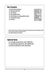
The box contents are for reference only. Box Contents GA-P31-S3G motherboard Motherboard driver disk User's Manual Quick Installation Guide One IDE cable and one floppy disk drive cable Two SATA 3Gb/s cables I/O Shield • The box contents above are subject to change without notice. • The motherboard image is for reference only and the actual items shall depend on product package you obtain. Optional Items 2-port USB 2.0 bracket (Part No. 12CR1-1UB030-51R) 2-port SATA power cable (Part No. 12CF1-2SERPW-01R) S/PDIF out cable (Part No. 12CR1-1SPOUT-02R) - 6 -
The box contents are for reference only. Box Contents GA-P31-S3G motherboard Motherboard driver disk User's Manual Quick Installation Guide One IDE cable and one floppy disk drive cable Two SATA 3Gb/s cables I/O Shield • The box contents above are subject to change without notice. • The motherboard image is for reference only and the actual items shall depend on product package you obtain. Optional Items 2-port USB 2.0 bracket (Part No. 12CR1-1UB030-51R) 2-port SATA power cable (Part No. 12CF1-2SERPW-01R) S/PDIF out cable (Part No. 12CR1-1SPOUT-02R) - 6 -

Manual
Page 7
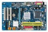
GA-P31-S3G Motherboard Layout KB_MS ATX_12V LGA775 CPU_FAN COMA LPT GA-P31-S3G ATX USB R_USB LAN CD_IN SPDIF_O AUDIO F_AUDIO RTL8111B IT8718 CODEC PCIE_1 PCIE_16 PCIE_2 PCIE_3 PCI1 PCI2 PCI3 Intel® P31 IDE SATAII2 Intel® ICH7 SATAII3 BAT CLR_CMOS F_USB1 F_USB2 SATAII0 MBIOS FDD SYS_FAN CI SATAII1 DDRII1 DDRII2 PWR_LED F_PANEL - 7 -
GA-P31-S3G Motherboard Layout KB_MS ATX_12V LGA775 CPU_FAN COMA LPT GA-P31-S3G ATX USB R_USB LAN CD_IN SPDIF_O AUDIO F_AUDIO RTL8111B IT8718 CODEC PCIE_1 PCIE_16 PCIE_2 PCIE_3 PCI1 PCI2 PCI3 Intel® P31 IDE SATAII2 Intel® ICH7 SATAII3 BAT CLR_CMOS F_USB1 F_USB2 SATAII0 MBIOS FDD SYS_FAN CI SATAII1 DDRII1 DDRII2 PWR_LED F_PANEL - 7 -

Manual
Page 9
...remove the AC power by your hands dry and first touch a metal object to eliminate static electricity. • Prior to installing the motherboard, please have a problem related to wear an electrostatic discharge (ESD) wrist strap when handling electronic components such as a result of the... to the use of electrostatic discharge (ESD). Hardware Installation These stickers are connected tightly and securely. • When handling the motherboard, avoid touching any installation steps or have it on top of an antistatic pad or within an electrostatic shielding container. •...
...remove the AC power by your hands dry and first touch a metal object to eliminate static electricity. • Prior to installing the motherboard, please have a problem related to wear an electrostatic discharge (ESD) wrist strap when handling electronic components such as a result of the... to the use of electrostatic discharge (ESD). Hardware Installation These stickers are connected tightly and securely. • When handling the motherboard, avoid touching any installation steps or have it on top of an antistatic pad or within an electrostatic shielding container. •...

Manual
Page 10
...Edition/Intel® Pentium® 4 processor/ Intel® Celeron® processor in the LGA 775 package (Go to GIGABYTE's website for the latest CPU support list.) Š L2 cache varies with CPU Š 1333/1066/800 MHz FSB Š...of system memory Š Dual channel memory architecture Š Support for DDR2 1066/800/667 MHz memory modules (Go to GIGABYTE's website for the latest memory support list.) Š Realtek ALC662 codec Š High Definition Audio Š 2/4/5.1-channel ...on the back panel, 4 via the USB brackets connected to the internal USB headers) GA-P31-S3G Motherboard - 10 -
...Edition/Intel® Pentium® 4 processor/ Intel® Celeron® processor in the LGA 775 package (Go to GIGABYTE's website for the latest CPU support list.) Š L2 cache varies with CPU Š 1333/1066/800 MHz FSB Š...of system memory Š Dual channel memory architecture Š Support for DDR2 1066/800/667 MHz memory modules (Go to GIGABYTE's website for the latest memory support list.) Š Realtek ALC662 codec Š High Definition Audio Š 2/4/5.1-channel ...on the back panel, 4 via the USB brackets connected to the internal USB headers) GA-P31-S3G Motherboard - 10 -

Manual
Page 12
GA-P31-S3G Motherboard - 12 - Unique Features Bundled Software Operating System Form Factor Š Support for @BIOS Š Support for Download Center Š Support for Q-Flash Š Support for EasyTune (Note) Š Support for Xpress Install Š Support for Xpress Recovery2 Š Support for Virtual Dual BIOS Š Norton Internet Security (OEM version) Š Support for Microsoft® Windows® Vista/XP/2000 Š ATX Form Factor; 30.5cm x 19.4cm (Note) Available functions in Easytune may differ by motherboard model.
GA-P31-S3G Motherboard - 12 - Unique Features Bundled Software Operating System Form Factor Š Support for @BIOS Š Support for Download Center Š Support for Q-Flash Š Support for EasyTune (Note) Š Support for Xpress Install Š Support for Xpress Recovery2 Š Support for Virtual Dual BIOS Š Norton Internet Security (OEM version) Š Support for Microsoft® Windows® Vista/XP/2000 Š ATX Form Factor; 30.5cm x 19.4cm (Note) Available functions in Easytune may differ by motherboard model.

Manual
Page 13
...hardware specifications since it does not meet the standard requirements for the latest CPU support list.) • Always turn on the CPU. mended that the motherboard supports the CPU. (Go to your hardware specifications including the CPU, graphics card, memory, hard drive, etc. 1-3-1 Installing the CPU A. Locate ... bus frequency be inserted if oriented incorrectly. (Or you wish to set beyond the standard specifications, please do so according to GIGABYTE's website for the peripherals. If you may occur. • Set the CPU host frequency in accordance with the CPU specifications.
...hardware specifications since it does not meet the standard requirements for the latest CPU support list.) • Always turn on the CPU. mended that the motherboard supports the CPU. (Go to your hardware specifications including the CPU, graphics card, memory, hard drive, etc. 1-3-1 Installing the CPU A. Locate ... bus frequency be inserted if oriented incorrectly. (Or you wish to set beyond the standard specifications, please do so according to GIGABYTE's website for the peripherals. If you may occur. • Set the CPU host frequency in accordance with the CPU specifications.

Manual
Page 14
... the motherboard CPU socket. B. Align the CPU pin one marking (triangle) with the pin one corner of the CPU socket (or you may align the CPU notches with your thumb and index fingers. Follow the steps below to the CPU. CPU Socket Lever Step 1: Completely raise the CPU socket lever. GA-P31-S3G Motherboard - 14...
... the motherboard CPU socket. B. Align the CPU pin one marking (triangle) with the pin one corner of the CPU socket (or you may align the CPU notches with your thumb and index fingers. Follow the steps below to the CPU. CPU Socket Lever Step 1: Completely raise the CPU socket lever. GA-P31-S3G Motherboard - 14...

Manual
Page 15
... for instructions on installing the cooler.) Step 5: After the installation, check the back of the motherboard. Step 6: Finally, attach the power connector of arrow is to the CPU fan header (CPU_FAN) on the motherboard. 1-3-2 Installing the CPU Cooler Follow the steps below to correctly install the CPU cooler on the...above, the installation is to install.) Step 3: Place the cooler atop the CPU, aligning the four push pins through the pin holes on the motherboard. Direction of the Arrow Sign on the Male Push Pin Male Push Pin The Top of Female Push Pin Female Push Pin Step 2: Before ...
... for instructions on installing the cooler.) Step 5: After the installation, check the back of the motherboard. Step 6: Finally, attach the power connector of arrow is to the CPU fan header (CPU_FAN) on the motherboard. 1-3-2 Installing the CPU Cooler Follow the steps below to correctly install the CPU cooler on the...above, the installation is to install.) Step 3: Place the cooler atop the CPU, aligning the four push pins through the pin holes on the motherboard. Direction of the Arrow Sign on the Male Push Pin Male Push Pin The Top of Female Push Pin Female Push Pin Step 2: Before ...

Manual
Page 16
...if only one DDR2 memory module is recommended that memory of the same capacity, brand, speed, and chips be used . (Go to GIGABYTE's website for the latest memory support list.) • Always turn off the computer and unplug the power cord from the power outlet ... two DDR2 memory sockets are unable to prevent hardware damage. • Memory modules have a foolproof design. A memory module can be used . GA-P31-S3G Motherboard - 16 - It is installed, the BIOS will double the original memory bandwidth. Enabling Dual Channel memory mode will automatically detect the specifications and ...
...if only one DDR2 memory module is recommended that memory of the same capacity, brand, speed, and chips be used . (Go to GIGABYTE's website for the latest memory support list.) • Always turn off the computer and unplug the power cord from the power outlet ... two DDR2 memory sockets are unable to prevent hardware damage. • Memory modules have a foolproof design. A memory module can be used . GA-P31-S3G Motherboard - 16 - It is installed, the BIOS will double the original memory bandwidth. Enabling Dual Channel memory mode will automatically detect the specifications and ...

Manual
Page 17
... , make sure to turn off the computer and unplug the power cord from the power outlet to prevent damage to install DDR2 DIMMs on this motherboard. Follow the steps below to correctly install your fingers on the memory and insert it can only fit in the memory sockets. Step 1: Note the...
... , make sure to turn off the computer and unplug the power cord from the power outlet to prevent damage to install DDR2 DIMMs on this motherboard. Follow the steps below to correctly install your fingers on the memory and insert it can only fit in the memory sockets. Step 1: Note the...

Manual
Page 18
... the expansion card. If necessary, go to BIOS Setup to the chassis back panel with the expansion card in the slot. 3. GA-P31-S3G Motherboard - 18 - Locate an expansion slot that came with the slot, and press down on the card are completely inserted into the PCI Express x16 slot. ...
... the expansion card. If necessary, go to BIOS Setup to the chassis back panel with the expansion card in the slot. 3. GA-P31-S3G Motherboard - 18 - Locate an expansion slot that came with the slot, and press down on the card are completely inserted into the PCI Express x16 slot. ...

Manual
Page 19
...-45 LAN Port The Gigabit Ethernet LAN port provides Internet connection at up to connect a PS/2 keyboard. Do not rock it straight out from the motherboard. • When removing the cable, pull it side to side to prevent an electrical short inside the cable connector. - 19 - 1-6 Back Panel Connectors PS/2 Keyboard...
...-45 LAN Port The Gigabit Ethernet LAN port provides Internet connection at up to connect a PS/2 keyboard. Do not rock it straight out from the motherboard. • When removing the cable, pull it side to side to prevent an electrical short inside the cable connector. - 19 - 1-6 Back Panel Connectors PS/2 Keyboard...

Manual
Page 20
Line Out Jack (Green) The default line out jack. Mic In Jack (Pink) The default Mic in Chapter 5, "Configuring 2/4/5.1-Channel Audio." Microphones must be used to connect front speakers in a 4/5.1-channel audio configuration. GA-P31-S3G Motherboard - 20 - This jack can be connected to the instructions on setting up a 2/4/5.1-channel audio configuration in jack. Use this audio jack for line in jack. Refer to this audio jack for a headphone or 2-channel speaker. Use this jack. Line In Jack (Blue) The default line in devices such as an optical drive, walkman, etc.
Line Out Jack (Green) The default line out jack. Mic In Jack (Pink) The default Mic in Chapter 5, "Configuring 2/4/5.1-Channel Audio." Microphones must be used to connect front speakers in a 4/5.1-channel audio configuration. GA-P31-S3G Motherboard - 20 - This jack can be connected to the instructions on setting up a 2/4/5.1-channel audio configuration in jack. Use this audio jack for line in jack. Refer to this audio jack for a headphone or 2-channel speaker. Use this jack. Line In Jack (Blue) The default line in devices such as an optical drive, walkman, etc.

Manual
Page 21
... connectors you wish to connect. • Before installing the devices, be sure to the devices. • After installing the device and before turning on the motherboard. - 21 -
... connectors you wish to connect. • Before installing the devices, be sure to the devices. • After installing the device and before turning on the motherboard. - 21 -

Manual
Page 22
..., the power supply can lead to an unstable or unbootable system. • The main power connector is turned off and all the components on the motherboard. When using a 2x10 power supply. 3 4 1 2 ATX_12V ATX_12V: Pin No. 1 2 3 4 Definition GND GND +12V +12V 12 24 1 13 ATX ATX: Pin No. 1 2 3 4 5 6 7 8 9 ...12V GND PS_ON(soft On/Off) GND GND GND -5V +5V +5V +5V (Only for 2x12-pin ATX) GND (Only for 2x12-pin ATX) GA-P31-S3G Motherboard - 22 - Do not insert the power supply cable into pins under the protective cover when using a 2x12 power supply, remove the protective cover from ...
..., the power supply can lead to an unstable or unbootable system. • The main power connector is turned off and all the components on the motherboard. When using a 2x10 power supply. 3 4 1 2 ATX_12V ATX_12V: Pin No. 1 2 3 4 Definition GND GND +12V +12V 12 24 1 13 ATX ATX: Pin No. 1 2 3 4 5 6 7 8 9 ...12V GND PS_ON(soft On/Off) GND GND GND -5V +5V +5V +5V (Only for 2x12-pin ATX) GND (Only for 2x12-pin ATX) GA-P31-S3G Motherboard - 22 - Do not insert the power supply cable into pins under the protective cover when using a 2x12 power supply, remove the protective cover from ...

Manual
Page 23
...-coded power connector wires. Hardware Installation When connecting a fan cable, be sure to the CPU or the system may result in the correct orientation. The motherboard supports CPU fan speed control, which requires the use of different color. 33 1 34 2 - 23 - Overheating may hang. • These fan headers are not ... Before connecting a floppy disk drive, be sure to connect it is used to prevent your CPU and system from overheating. 3/4) CPU_FAN/SYS_FAN (Fan Headers) The motherboard has a 4-pin CPU fan header (CPU_FAN) and a 3-pin system fan header (SYS_FAN).
...-coded power connector wires. Hardware Installation When connecting a fan cable, be sure to the CPU or the system may result in the correct orientation. The motherboard supports CPU fan speed control, which requires the use of different color. 33 1 34 2 - 23 - Overheating may hang. • These fan headers are not ... Before connecting a floppy disk drive, be sure to connect it is used to prevent your CPU and system from overheating. 3/4) CPU_FAN/SYS_FAN (Fan Headers) The motherboard has a 4-pin CPU fan header (CPU_FAN) and a 3-pin system fan header (SYS_FAN).


