Manual
Page 4
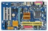
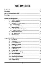
... ...6 GA-P31-ES3G Motherboard Layout 7 Block Diagram ...8 Chapter 1 Hardware Installation 9 1-1 Installation Precautions 9 1-2 Product Specifications 10 1-3 Installing the CPU and CPU Cooler 13 1-3-1 Installing the CPU 13 1-3-2 Installing the CPU Cooler 15 1-4 Installing the Memory 16 1-4-1 Dual Channel Memory Configuration 16 1-4-2 Installing a Memory 17 1-5 Installing an Expansion Card 18 1-6 Back Panel Connectors 19 1-7 Internal Connectors 21 Chapter 2 BIOS Setup 31 2-1 Startup Screen 32 2-2 The Main Menu 33 2-3 Standard CMOS Features 35 2-4 Advanced BIOS Features...
... ...6 GA-P31-ES3G Motherboard Layout 7 Block Diagram ...8 Chapter 1 Hardware Installation 9 1-1 Installation Precautions 9 1-2 Product Specifications 10 1-3 Installing the CPU and CPU Cooler 13 1-3-1 Installing the CPU 13 1-3-2 Installing the CPU Cooler 15 1-4 Installing the Memory 16 1-4-1 Dual Channel Memory Configuration 16 1-4-2 Installing a Memory 17 1-5 Installing an Expansion Card 18 1-6 Back Panel Connectors 19 1-7 Internal Connectors 21 Chapter 2 BIOS Setup 31 2-1 Startup Screen 32 2-2 The Main Menu 33 2-3 Standard CMOS Features 35 2-4 Advanced BIOS Features...
Manual
Page 12
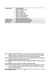
... version) Š Support for Microsoft® Windows® Vista/XP Š ATX Form Factor; 30.5cm x 19.4cm (Note 1) Based on the CPU cooler you install. (Note 4) Available functions in EasyTune may differ by motherboard model. (Note 5) Due to the hardware limitation, you have to use an HD front panel audio module and enable the multi-channel audio feature through the audio driver. (Note 3) Whether the CPU fan speed control...
... version) Š Support for Microsoft® Windows® Vista/XP Š ATX Form Factor; 30.5cm x 19.4cm (Note 1) Based on the CPU cooler you install. (Note 4) Available functions in EasyTune may differ by motherboard model. (Note 5) Due to the hardware limitation, you have to use an HD front panel audio module and enable the multi-channel audio feature through the audio driver. (Note 3) Whether the CPU fan speed control...
Manual
Page 16
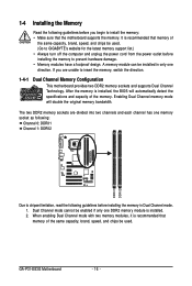
... enabled if only one direction. GA-P31-ES3G Motherboard - 16 - When enabling Dual Channel mode with two memory modules, it is installed, the BIOS will double the original memory bandwidth. Enabling Dual Channel memory mode will automatically detect the specifications and capacity of the same capacity, brand, speed, and chips be installed in Dual Channel mode. 1. It is installed. 2. A memory module can be used . (Go to GIGABYTE's website for the latest memory support list.) • Always turn off the computer and unplug the power...
... enabled if only one direction. GA-P31-ES3G Motherboard - 16 - When enabling Dual Channel mode with two memory modules, it is installed, the BIOS will double the original memory bandwidth. Enabling Dual Channel memory mode will automatically detect the specifications and capacity of the same capacity, brand, speed, and chips be installed in Dual Channel mode. 1. It is installed. 2. A memory module can be used . (Go to GIGABYTE's website for the latest memory support list.) • Always turn off the computer and unplug the power...
Manual
Page 18
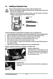
... damage. PCI Express x1 Slot PCI Express x16 Slot PCI Slot Follow the steps below to install an expansion card: • Make sure the motherboard supports the expansion card. Locate an expansion slot that came with a screw. 5. After installing all expansion cards, replace the chassis cover(s). 6. Carefully read the manual that supports your operating system. Example: Installing and Removing a PCI Express x16 Graphics Card: • Installing a Graphics Card: Gently push down on the card are completely inserted into the PCI Express x16 slot. GA-P31-ES3G Motherboard - 18...
... damage. PCI Express x1 Slot PCI Express x16 Slot PCI Slot Follow the steps below to install an expansion card: • Make sure the motherboard supports the expansion card. Locate an expansion slot that came with a screw. 5. After installing all expansion cards, replace the chassis cover(s). 6. Carefully read the manual that supports your operating system. Example: Installing and Removing a PCI Express x16 Graphics Card: • Installing a Graphics Card: Gently push down on the card are completely inserted into the PCI Express x16 slot. GA-P31-ES3G Motherboard - 18...
Manual
Page 25
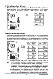
... in Chapter 5, "Configuring 2/4/5.1/7.1-Channel Audio." • Audio signals will make the device unable to indicate system power status. Definition 1 MPD+ 2 MPD- 1 3 MPD- Incorrect connection between the module connector and the motherboard header will be used to connect a system power LED on how to Chapter 5, "Configuring 2/4/5.1/7.1-Channel Audio." • Some chassis provide a front panel audio module that has different wire assignments, please contact the chassis manufacturer. - 25 - For HD Front Panel Audio: Pin No. Definition 2 10...
... in Chapter 5, "Configuring 2/4/5.1/7.1-Channel Audio." • Audio signals will make the device unable to indicate system power status. Definition 1 MPD+ 2 MPD- 1 3 MPD- Incorrect connection between the module connector and the motherboard header will be used to connect a system power LED on how to Chapter 5, "Configuring 2/4/5.1/7.1-Channel Audio." • Some chassis provide a front panel audio module that has different wire assignments, please contact the chassis manufacturer. - 25 - For HD Front Panel Audio: Pin No. Definition 2 10...
Manual
Page 28
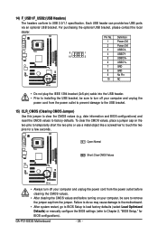
... short the two pins or use a metal object like a screwdriver to factory defaults. Open: Normal Short: Clear CMOS Values • Always turn off your computer, be sure to clear the CMOS values (e.g. Failure to do so may cause damage to the motherboard. • After system restart, go to BIOS Setup to load factory defaults (select Load Optimized Defaults) or manually configure the BIOS settings (refer to USB 2.0/1.1 specification. Each USB header can provide two USB ports via an optional USB...
... short the two pins or use a metal object like a screwdriver to factory defaults. Open: Normal Short: Clear CMOS Values • Always turn off your computer, be sure to clear the CMOS values (e.g. Failure to do so may cause damage to the motherboard. • After system restart, go to BIOS Setup to load factory defaults (select Load Optimized Defaults) or manually configure the BIOS settings (refer to USB 2.0/1.1 specification. Each USB header can provide two USB ports via an optional USB...
Manual
Page 32
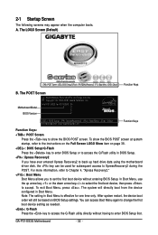
... Screen (Default) :POST Screen :BIOS Setup/Q-Flash :XpressRecovery2 :Boot Menu :Qflash Function Keys B. GA-P31-ES3G Motherboard - 32 - To exit Boot Menu, press . The POST Screen Award Modular BIOS v6.00PG, An Energy Star Ally Copyright (C) 1984-2008, Award Software, Inc. In Boot Menu, use the up hard drive data using the motherboard driver disk, the key can access Boot Menu again to change the first boot device setting as needed. : Q-Flash Press the key to access the Q-Flash utility directly without entering BIOS Setup. To show the BIOS POST screen. Note: The setting in Boot...
... Screen (Default) :POST Screen :BIOS Setup/Q-Flash :XpressRecovery2 :Boot Menu :Qflash Function Keys B. GA-P31-ES3G Motherboard - 32 - To exit Boot Menu, press . The POST Screen Award Modular BIOS v6.00PG, An Energy Star Ally Copyright (C) 1984-2008, Award Software, Inc. In Boot Menu, use the up hard drive data using the motherboard driver disk, the key can access Boot Menu again to change the first boot device setting as needed. : Q-Flash Press the key to access the Q-Flash utility directly without entering BIOS Setup. To show the BIOS POST screen. Note: The setting in Boot...
Manual
Page 34
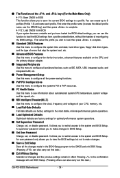
..., hard drive types, floppy disk drive types, and the type of errors that stop the system boot, etc. „ Advanced BIOS Features Use this menu to configure the device boot order, advanced features available on the CPU, and the primary display adapter. „ Integrated Peripherals Use this menu to configure all peripheral devices, such as IDE, SATA, USB, integrated audio, and integrated LAN, etc. „ Power Management Setup Use this menu to configure all the power-saving functions. „ PnP/PCI Configurations Use this menu to configure the...
..., hard drive types, floppy disk drive types, and the type of errors that stop the system boot, etc. „ Advanced BIOS Features Use this menu to configure the device boot order, advanced features available on the CPU, and the primary display adapter. „ Integrated Peripherals Use this menu to configure all peripheral devices, such as IDE, SATA, USB, integrated audio, and integrated LAN, etc. „ Power Management Setup Use this menu to configure all the power-saving functions. „ PnP/PCI Configurations Use this menu to configure the...

Manual
Page 35
... of the device during the POST for faster system startup. • Manual Access Mode Allows you to manually enter the specifications of the hard drive when the hard drive access mode is set this channel. Sets the hard drive access mode. Options are : Auto (default), CHS, LBA, Large. is week (read-only), month, date and year. IDE Channel 0 Master/Slave Configure your IDE/SATA devices by using one of the IDE/SATA device on this channel. The date format is 13:0:0. IDE Channel 0 Master/Slave IDE HDD Auto-Detection Press...
... of the device during the POST for faster system startup. • Manual Access Mode Allows you to manually enter the specifications of the hard drive when the hard drive access mode is set this channel. Sets the hard drive access mode. Options are : Auto (default), CHS, LBA, Large. is week (read-only), month, date and year. IDE Channel 0 Master/Slave Configure your IDE/SATA devices by using one of the IDE/SATA device on this channel. The date format is 13:0:0. IDE Channel 0 Master/Slave IDE HDD Auto-Detection Press...
Manual
Page 37
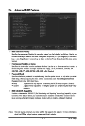
... list. This feature allows your hard drive. Options are: Floppy, LS120, Hard Disk, CDROM, ZIP, USB-FDD, USB-ZIP, USB-CDROM, USB-HDD, LAN, Disabled. First/Second/Third Boot Device Specifies the boot order from the installed hard drives. BIOS Setup HDD S.M.A.R.T. to 3 (Note) No-Execute Memory Protect (Note) CPU Enhanced Halt (C1E) (Note) CPU Thermal Monitor 2(TM2) (Note) CPU EIST Function (Note) Virtualization Technology (Note) Full Screen LOGO Show Init Display First [Press Enter] [Floppy] [Hard Disk] [CDROM] [Setup] [Disabled] [Disabled] [Enabled] [Enabled] [Enabled...
... list. This feature allows your hard drive. Options are: Floppy, LS120, Hard Disk, CDROM, ZIP, USB-FDD, USB-ZIP, USB-CDROM, USB-HDD, LAN, Disabled. First/Second/Third Boot Device Specifies the boot order from the installed hard drives. BIOS Setup HDD S.M.A.R.T. to 3 (Note) No-Execute Memory Protect (Note) CPU Enhanced Halt (C1E) (Note) CPU Thermal Monitor 2(TM2) (Note) CPU EIST Function (Note) Virtualization Technology (Note) Full Screen LOGO Show Init Display First [Press Enter] [Floppy] [Hard Disk] [CDROM] [Setup] [Disabled] [Disabled] [Enabled] [Enabled] [Enabled...
Manual
Page 38
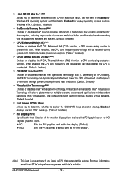
... when working with its supporting software and system. (Default: Enabled) CPU Enhanced Halt (C1E) (Note) Enables or disables Intel® CPU Enhanced Halt (C1E) function, a CPU power-saving function in independent partitions. Disabled displays normal POST message. (Default: Enabled) Init Display First Specifies the first initiation of the monitor display from the installed PCI graphics card or PCI Express graphics card. Depending on CPU loading, Intel® EIST technology can function as multiple virtual systems. (Default: Enabled) Full Screen LOGO Show Allows you install a CPU that...
... when working with its supporting software and system. (Default: Enabled) CPU Enhanced Halt (C1E) (Note) Enables or disables Intel® CPU Enhanced Halt (C1E) function, a CPU power-saving function in independent partitions. Disabled displays normal POST message. (Default: Enabled) Init Display First Specifies the first initiation of the monitor display from the installed PCI graphics card or PCI Express graphics card. Depending on CPU loading, Intel® EIST technology can function as multiple virtual systems. (Default: Enabled) Full Screen LOGO Show Allows you install a CPU that...
Manual
Page 39
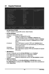
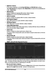
... CMOS Setup Utility-Copyright (C) 1984-2008 Award Software Integrated Peripherals On-Chip Primary PCI IDE On-Chip SATA Mode x PATA IDE Set to SATA Port 0/2 Set to SATA Port 1/3 Set to operate in SATA mode. If your onboard SATA controller is set SATA devices to operate in PATA mode. When PATA IDE Set to is selected. Sets all SATA devices to USB Controller USB 2.0 Controller USB Keyboard Support USB Mouse Support Legacy USB storage detect Azalia Codec Onboard H/W LAN ` SMART LAN Onboard LAN Boot ROM Onboard Serial Port 1 Onboard Parallel Port Parallel Port Mode [Enabled] [Auto...
... CMOS Setup Utility-Copyright (C) 1984-2008 Award Software Integrated Peripherals On-Chip Primary PCI IDE On-Chip SATA Mode x PATA IDE Set to SATA Port 0/2 Set to SATA Port 1/3 Set to operate in SATA mode. If your onboard SATA controller is set SATA devices to operate in PATA mode. When PATA IDE Set to is selected. Sets all SATA devices to USB Controller USB 2.0 Controller USB Keyboard Support USB Mouse Support Legacy USB storage detect Azalia Codec Onboard H/W LAN ` SMART LAN Onboard LAN Boot ROM Onboard Serial Port 1 Onboard Parallel Port Parallel Port Mode [Enabled] [Auto...
Manual
Page 40
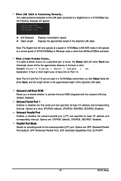
... or short. GA-P31-ES3G Motherboard - 40 - USB Controller Enables or disables the integrated USB controller. (Default: Enabled) Disabled will be used in the figure above. SATA Port 1/3 Set to This value is configured to Ch. 0 Master/Slave, this item to Disabled. When PATA IDE Set to is dependent on the On-Chip SATA Mode and PATA IDE Set to the following information for diagnosing your LAN cable: When No LAN Cable Is Attached... SMART LAN (LAN Cable Diagnostic Function) CMOS Setup Utility-Copyright (C) 1984-2008 Award Software SMART LAN Start detecting at Port.....
... or short. GA-P31-ES3G Motherboard - 40 - USB Controller Enables or disables the integrated USB controller. (Default: Enabled) Disabled will be used in the figure above. SATA Port 1/3 Set to This value is configured to Ch. 0 Master/Slave, this item to Disabled. When PATA IDE Set to is dependent on the On-Chip SATA Mode and PATA IDE Set to the following information for diagnosing your LAN cable: When No LAN Cable Is Attached... SMART LAN (LAN Cable Diagnostic Function) CMOS Setup Utility-Copyright (C) 1984-2008 Award Software SMART LAN Start detecting at Port.....
Manual
Page 41
... the boot ROM integrated with the onboard LAN chip. (Default: Disabled) Onboard Serial Port 1 Enables or disables the first serial port and specifies its base I /O address and corresponding interrupt. Onboard Parallel Port Enables or disables the onboard parallel port (LPT) and specifies its base I /O address and corresponding interrupt. BIOS Setup it will operate at Port..... If a cable problem occurs on a specified pair of 10/100/1000Mbps in Windows mode or when the LAN Boot ROM is activated. Example: Part1-2 Status = Short...
... the boot ROM integrated with the onboard LAN chip. (Default: Disabled) Onboard Serial Port 1 Enables or disables the first serial port and specifies its base I /O address and corresponding interrupt. Onboard Parallel Port Enables or disables the onboard parallel port (LPT) and specifies its base I /O address and corresponding interrupt. BIOS Setup it will operate at Port..... If a cable problem occurs on a specified pair of 10/100/1000Mbps in Windows mode or when the LAN Boot ROM is activated. Example: Part1-2 Status = Short...
Manual
Page 47
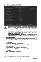
... is recommended that supports this occurs, clear the CMOS values and reset the board to enhance the performance of these components. Incorrectly doing overclock/overvoltage may result in red, it is installed. Auto allows the BIOS to automatically set the System Voltage Control item to Auto to boot. 2-9 MB Intelligent Tweaker(M.I.T.) CMOS Setup Utility-Copyright (C) 1984-2008 Award Software MB Intelligent Tweaker(M.I.T.) Robust Graphics Booster CPU Clock Ratio (Note) Fine CPU Clock Ratio (Note) x CPU Frequency O.C.
... is recommended that supports this occurs, clear the CMOS values and reset the board to enhance the performance of these components. Incorrectly doing overclock/overvoltage may result in red, it is installed. Auto allows the BIOS to automatically set the System Voltage Control item to Auto to boot. 2-9 MB Intelligent Tweaker(M.I.T.) CMOS Setup Utility-Copyright (C) 1984-2008 Award Software MB Intelligent Tweaker(M.I.T.) Robust Graphics Booster CPU Clock Ratio (Note) Fine CPU Clock Ratio (Note) x CPU Frequency O.C.
Manual
Page 52
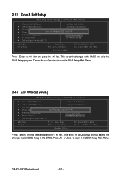
... BIOS Setup to the CMOS and exits the BIOS Setup program. This saves the changes to the CMOS. Press or to return to the BIOS Setup Main Menu. GA-P31-ES3G Motherboard - 52 - Press or to return to the BIOS Setup Main Menu. 2-14 Exit Without Saving CMOS Setup Utility-Copyright (C) 1984-2008 Award Software ` Standard CMOS Features Load Fail-Safe Defaults ` Advanced BIOS Features Load Optimized Defaults ` Integrated Peripherals Set Supervisor Password ` Power Management Setup Quit Without Saving (SYe/tNU)?seNr Password ` PnP/PCI Configurations Save & Exit Setup...
... BIOS Setup to the CMOS and exits the BIOS Setup program. This saves the changes to the CMOS. Press or to return to the BIOS Setup Main Menu. GA-P31-ES3G Motherboard - 52 - Press or to return to the BIOS Setup Main Menu. 2-14 Exit Without Saving CMOS Setup Utility-Copyright (C) 1984-2008 Award Software ` Standard CMOS Features Load Fail-Safe Defaults ` Advanced BIOS Features Load Optimized Defaults ` Integrated Peripherals Set Supervisor Password ` Power Management Setup Quit Without Saving (SYe/tNU)?seNr Password ` PnP/PCI Configurations Save & Exit Setup...
Manual
Page 62
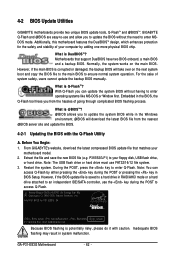
... new BIOS file (e.g. Restart the system. GA-P31-ES3G Motherboard - 62 - However, if the main BIOS is potentially risky, please do it with the Q-Flash Utility A. Intel P31 BIOS for the safety and stability of your floppy disk, USB flash drive, or hard drive. What is saved to a hard drive in BIOS Setup. Note: The USB flash drive or hard drive must use the key during the POST or pressing the key in RAID/AHCI mode or a hard drive attached to an independent IDE/SATA controller, use FAT32/16/12 file system...
... new BIOS file (e.g. Restart the system. GA-P31-ES3G Motherboard - 62 - However, if the main BIOS is potentially risky, please do it with the Q-Flash Utility A. Intel P31 BIOS for the safety and stability of your floppy disk, USB flash drive, or hard drive. What is saved to a hard drive in BIOS Setup. Note: The USB flash drive or hard drive must use the key during the POST or pressing the key in RAID/AHCI mode or a hard drive attached to an independent IDE/SATA controller, use FAT32/16/12 file system...
Manual
Page 63
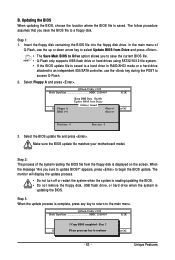
... a hard drive in RAID/AHCI mode or a hard drive attached to an independent IDE/SATA controller, use the key during the POST to a floppy disk. Select Floppy A and press . Unique Features Insert the floppy disk containing the BIOS file into the floppy disk drive. In the main menu of the system reading the BIOS file from Drive Sa0vefilBeI(Os)SfotounDdrive KL:Move ESC:Reset :Power Off Total size : 0 Free size : 0 3. Select the BIOS update file and press . Make sure the BIOS update file matches your motherboard model. The monitor will display the update process...
... a hard drive in RAID/AHCI mode or a hard drive attached to an independent IDE/SATA controller, use the key during the POST to a floppy disk. Select Floppy A and press . Unique Features Insert the floppy disk containing the BIOS file into the floppy disk drive. In the main menu of the system reading the BIOS file from Drive Sa0vefilBeI(Os)SfotounDdrive KL:Move ESC:Reset :Power Off Total size : 0 Free size : 0 3. Select the BIOS update file and press . Make sure the BIOS update file matches your motherboard model. The monitor will display the update process...
Manual
Page 69
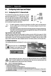
... supported when using an HD front panel audio module), refer to the configurations on page 71. Configuring Speakers: (The following for each jack through the audio driver. Doubleclick the icon to the right shows the default audio jack assignments. For example, users can listen to change the function for multi-channel speaker configurations. • 2 -channel audio: Headphone or Line out. • 4- The picture to access the Audio Control Panel. The integrated HD (High...
... supported when using an HD front panel audio module), refer to the configurations on page 71. Configuring Speakers: (The following for each jack through the audio driver. Doubleclick the icon to the right shows the default audio jack assignments. For example, users can listen to change the function for multi-channel speaker configurations. • 2 -channel audio: Headphone or Line out. • 4- The picture to access the Audio Control Panel. The integrated HD (High...
Manual
Page 76
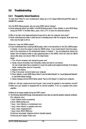
... beep code descriptions may help you identify possible computer problems. (For reference only.) 1 short: System boots successfully 2 short: CMOS setting error 1 long, 1 short: Memory or motherboard error 1 long, 2 short: Monitor or graphics card error 1 long, 3 short: Keyboard error 1 long, 9 short: BIOS ROM error Continuous long beeps: Graphics card not inserted properly Continuous short beeps: Power error GA-P31-ES3G Motherboard - 76 - If your computer and unplug the power cord. 2. Saves changes and exit BIOS Setup (select "Save & Exit Setup") to show the advanced options. Plug...
... beep code descriptions may help you identify possible computer problems. (For reference only.) 1 short: System boots successfully 2 short: CMOS setting error 1 long, 1 short: Memory or motherboard error 1 long, 2 short: Monitor or graphics card error 1 long, 3 short: Keyboard error 1 long, 9 short: BIOS ROM error Continuous long beeps: Graphics card not inserted properly Continuous short beeps: Power error GA-P31-ES3G Motherboard - 76 - If your computer and unplug the power cord. 2. Saves changes and exit BIOS Setup (select "Save & Exit Setup") to show the advanced options. Plug...


