Manual
Page 1
GA-MA790X-UD3P AM2+/AM2 socket motherboard for AMD PhenomTM II X4 processor/AMD PhenomTM II X3 processor/ AMD PhenomTM FX processor/AMD PhenomTM X4 processor/ AMD PhenomTM X3 processor/AMD AthlonTM X2 processor/ AMD AthlonTM processor/AMD SempronTM X2 processor/ AMD SempronTM processor User's Manual Rev. 1001 12ME-MA79U3P-1001R
GA-MA790X-UD3P AM2+/AM2 socket motherboard for AMD PhenomTM II X4 processor/AMD PhenomTM II X3 processor/ AMD PhenomTM FX processor/AMD PhenomTM X4 processor/ AMD PhenomTM X3 processor/AMD AthlonTM X2 processor/ AMD AthlonTM processor/AMD SempronTM X2 processor/ AMD SempronTM processor User's Manual Rev. 1001 12ME-MA79U3P-1001R
Manual
Page 3
...: For quick set-up of GIGABYTE. Documentation Classifications In order to assist in this manual are legally registered to use GIGABYTE's unique features, read the User's Manual. For instructions on your motherboard revision before updating motherboard BIOS, drivers, or when looking for technical... information. For product-related information, check on our website at: http://www.gigabyte.com.tw Identifying Your Motherboard Revision The revision number on how to their respective owners. Disclaimer Information in any form or by any ...
...: For quick set-up of GIGABYTE. Documentation Classifications In order to assist in this manual are legally registered to use GIGABYTE's unique features, read the User's Manual. For instructions on your motherboard revision before updating motherboard BIOS, drivers, or when looking for technical... information. For product-related information, check on our website at: http://www.gigabyte.com.tw Identifying Your Motherboard Revision The revision number on how to their respective owners. Disclaimer Information in any form or by any ...
Manual
Page 4
Table of Contents Box Contents ...6 OptionalItems ...6 GA-MA790X-UD3P Motherboard Layout 7 Block Diagram ...8 Chapter 1 Hardware Installation 9 1-1 Installation Precautions 9 1-2 Product Specifications 10 1-3 Installing the CPU and CPU Cooler 13 1-3-1 Installing the CPU 13 1-3-2 Installing the CPU ...
Table of Contents Box Contents ...6 OptionalItems ...6 GA-MA790X-UD3P Motherboard Layout 7 Block Diagram ...8 Chapter 1 Hardware Installation 9 1-1 Installation Precautions 9 1-2 Product Specifications 10 1-3 Installing the CPU and CPU Cooler 13 1-3-1 Installing the CPU 13 1-3-2 Installing the CPU ...
Manual
Page 6
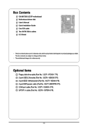
...-1IE008-0*R) 2-port SATA power cable (Part No. 12CF1-2SERPW-0*R) COM port cable (Part No. 12CF1-1CM001-3*R) S/PDIF in cable (Part No. 12CR1-1SPDIN-0*R) - 6 - Box Contents GA-MA790X-UD3P motherboard Motherboard driver disk User's Manual Quick Installation Guide One IDE cable Two SATA 3Gb/s cables I/O Shield • The box contents above are subject to change without...
...-1IE008-0*R) 2-port SATA power cable (Part No. 12CF1-2SERPW-0*R) COM port cable (Part No. 12CF1-1CM001-3*R) S/PDIF in cable (Part No. 12CR1-1SPDIN-0*R) - 6 - Box Contents GA-MA790X-UD3P motherboard Motherboard driver disk User's Manual Quick Installation Guide One IDE cable Two SATA 3Gb/s cables I/O Shield • The box contents above are subject to change without...
Manual
Page 7
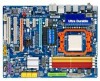
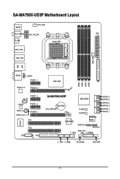
GA-MA790X-UD3P Motherboard Layout KB_MS CPU_FAN RCA_SPDIF ATX_12V_2X4 ATX R_USB Socket AM2 USB_1394_1 USB_1394 PWR_FAN USB IT8720 LAN AUDIO F_AUDIO PCIEX1_1 RTL8111C PCIEX16_1 PCIEX1_2 CD_IN CODEC PCIEX1_3 SPDIF_IN SPDIF_OUT PCIEX8_1 PCI1 PCI2 COM FDD CI DDR2_1 DDR2_2 DDR2_3 DDR2_4 AMD 790X IDE GA-MA790X-UD3P CLR_CMOS BATTERY AMD SB750 B_BIOS M_BIOS SATA2_4 SATA2_5 SATA2_2 SATA2_3 SATA2_0 SATA2_1 TSB43AB23 GIGABYTE SATA2 GSATA2_0 GSATA2_1 PWR_LED F_USB1 F_PANEL F_1394 F_USB2 SYS_FAN2 SYS_FAN1 - 7 -
GA-MA790X-UD3P Motherboard Layout KB_MS CPU_FAN RCA_SPDIF ATX_12V_2X4 ATX R_USB Socket AM2 USB_1394_1 USB_1394 PWR_FAN USB IT8720 LAN AUDIO F_AUDIO PCIEX1_1 RTL8111C PCIEX16_1 PCIEX1_2 CD_IN CODEC PCIEX1_3 SPDIF_IN SPDIF_OUT PCIEX8_1 PCI1 PCI2 COM FDD CI DDR2_1 DDR2_2 DDR2_3 DDR2_4 AMD 790X IDE GA-MA790X-UD3P CLR_CMOS BATTERY AMD SB750 B_BIOS M_BIOS SATA2_4 SATA2_5 SATA2_2 SATA2_3 SATA2_0 SATA2_1 TSB43AB23 GIGABYTE SATA2 GSATA2_0 GSATA2_1 PWR_LED F_USB1 F_PANEL F_1394 F_USB2 SYS_FAN2 SYS_FAN1 - 7 -
Manual
Page 9
... system in a high-temperature environment. • Turning on the power, make sure they are connected tightly and securely. • When handling the motherboard, avoid touching any installation steps or have a problem related to the use of the product, please consult a certified computer technician. - 9 - ...ESD wrist strap, keep your hands dry and first touch a metal object to eliminate static electricity. • Prior to installing the motherboard, please have it on top of an antistatic pad or within an electrostatic shielding container. • Before unplugging the power supply ...
... system in a high-temperature environment. • Turning on the power, make sure they are connected tightly and securely. • When handling the motherboard, avoid touching any installation steps or have a problem related to the use of the product, please consult a certified computer technician. - 9 - ...ESD wrist strap, keep your hands dry and first touch a metal object to eliminate static electricity. • Prior to installing the motherboard, please have it on top of an antistatic pad or within an electrostatic shielding container. • Before unplugging the power supply ...
Manual
Page 10
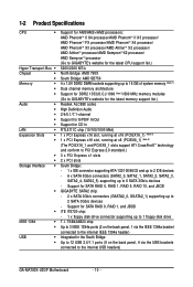
.../ AMD PhenomTM X3 processor/AMD AthlonTM X2 processor/ AMD AthlonTM processor/AMD SempronTM X2 processor/ AMD SempronTM processor (Go to GIGABYTE's website for the latest CPU support list.) 5200/2000 MT/s North Bridge: AMD 790X South Bridge: AMD SB750 4 ...6 x SATA 3Gb/s connectors (SATA2_0, SATA2_1, SATA2_2, SATA2_3, SATA2_4, SATA2_5) supporting up to the internal USB headers) GA-MA790X-UD3P Motherboard - 10 - Support for SATA RAID 0, RAID 1, RAID 5, RAID 10, and JBOD GIGABYTE SATA2 chip: - 2 x SATA 3Gb/s connectors (GSATA2_0, GSATA2_1) supporting up to 2 SATA 3Gb/s devices - Support ...
.../ AMD PhenomTM X3 processor/AMD AthlonTM X2 processor/ AMD AthlonTM processor/AMD SempronTM X2 processor/ AMD SempronTM processor (Go to GIGABYTE's website for the latest CPU support list.) 5200/2000 MT/s North Bridge: AMD 790X South Bridge: AMD SB750 4 ...6 x SATA 3Gb/s connectors (SATA2_0, SATA2_1, SATA2_2, SATA2_3, SATA2_4, SATA2_5) supporting up to the internal USB headers) GA-MA790X-UD3P Motherboard - 10 - Support for SATA RAID 0, RAID 1, RAID 5, RAID 10, and JBOD GIGABYTE SATA2 chip: - 2 x SATA 3Gb/s connectors (GSATA2_0, GSATA2_1) supporting up to 2 SATA 3Gb/s devices - Support ...
Manual
Page 12
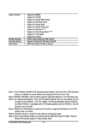
... memory size displayed will depend on the CPU/ system cooler you install. (Note 5) Available functions in EasyTune may differ by motherboard model. (Note 6) Due to install it in the PCIEX16_1 slot. GA-MA790X-UD3P Motherboard - 12 - Unique Features Bundled Software Operating System Form Factor Support for @BIOS Support for Q-Flash Support for...
... memory size displayed will depend on the CPU/ system cooler you install. (Note 5) Available functions in EasyTune may differ by motherboard model. (Note 6) Due to install it in the PCIEX16_1 slot. GA-MA790X-UD3P Motherboard - 12 - Unique Features Bundled Software Operating System Form Factor Support for @BIOS Support for Q-Flash Support for...
Manual
Page 13
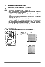
... Triangle Mark Denotes Pin One of the CPU may occur. • Set the CPU host frequency in accordance with the CPU specifications. mended that the motherboard supports the CPU. (Go to GIGABYTE's website for the peripherals.
... Triangle Mark Denotes Pin One of the CPU may occur. • Set the CPU host frequency in accordance with the CPU specifications. mended that the motherboard supports the CPU. (Go to GIGABYTE's website for the peripherals.
Manual
Page 14
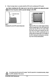
... to turn off the computer and unplug the power cord from the power outlet to prevent damage to correctly install the CPU into the motherboard CPU socket. B. GA-MA790X-UD3P Motherboard - 14 - Make sure that the CPU pins fit perfectly into the CPU socket. The CPU cannot fit in if oriented incorrectly. Adjust the CPU...
... to turn off the computer and unplug the power cord from the power outlet to prevent damage to correctly install the CPU into the motherboard CPU socket. B. GA-MA790X-UD3P Motherboard - 14 - Make sure that the CPU pins fit perfectly into the CPU socket. The CPU cannot fit in if oriented incorrectly. Adjust the CPU...
Manual
Page 15
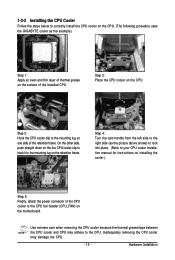
... frame. 1-3-2 Installing the CPU Cooler Follow the steps below to correctly install the CPU cooler on the CPU. (The following procedure uses the GIGABYTE cooler as the picture above shows) to lock into place. (Refer to your CPU cooler installation manual for instructions on installing the cooler.) Step... 5: Finally, attach the power connector of the CPU cooler to the CPU fan header (CPU_FAN) on the motherboard. Hardware Installation Step 2: Place the CPU cooler on one side of the installed CPU. On the other side, push straight down on the ...
... frame. 1-3-2 Installing the CPU Cooler Follow the steps below to correctly install the CPU cooler on the CPU. (The following procedure uses the GIGABYTE cooler as the picture above shows) to lock into place. (Refer to your CPU cooler installation manual for instructions on installing the cooler.) Step... 5: Finally, attach the power connector of the CPU cooler to the CPU fan header (CPU_FAN) on the motherboard. Hardware Installation Step 2: Place the CPU cooler on one side of the installed CPU. On the other side, push straight down on the ...
Manual
Page 16
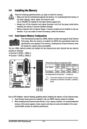
... DS/SS (SS=Single-Sided, DS=Double-Sided, "- -"=No Memory) If two memory modules are to be used . (Go to GIGABYTE's website for optimum performance. GA-MA790X-UD3P Motherboard - 16 - If you are divided into two channels and each channel has two memory sockets as following: Channel 0: DDR2_1, DDR2_3 Channel ...capacity, brand, speed, and chips be installed in only one DDR2 memory module is installed. 2. After the memory is recommended that the motherboard supports the memory. It is recommended that memory of the same capacity, brand, speed, and chips be installed, it is installed, the...
... DS/SS (SS=Single-Sided, DS=Double-Sided, "- -"=No Memory) If two memory modules are to be used . (Go to GIGABYTE's website for optimum performance. GA-MA790X-UD3P Motherboard - 16 - If you are divided into two channels and each channel has two memory sockets as following: Channel 0: DDR2_1, DDR2_3 Channel ...capacity, brand, speed, and chips be installed in only one DDR2 memory module is installed. 2. After the memory is recommended that the motherboard supports the memory. It is recommended that memory of the same capacity, brand, speed, and chips be installed, it is installed, the...
Manual
Page 17
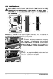
... , make sure to turn off the computer and unplug the power cord from the power outlet to prevent damage to install DDR2 DIMMs on this motherboard. DDR2 DIMMs are not compatible to DDR DIMMs. Be sure to the memory module.
... , make sure to turn off the computer and unplug the power cord from the power outlet to prevent damage to install DDR2 DIMMs on this motherboard. DDR2 DIMMs are not compatible to DDR DIMMs. Be sure to the memory module.
Manual
Page 18
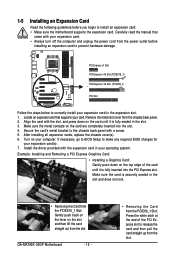
... (PCIEX8_1) PCI Slot Follow the steps below to install an expansion card: • Make sure the motherboard supports the expansion card. Align the card with a screw. 5. Secure the card's metal bracket to prevent hardware damage. GA-MA790X-UD3P Motherboard - 18 - • Removing the Card from the slot. If necessary, go to BIOS Setup to release...
... (PCIEX8_1) PCI Slot Follow the steps below to install an expansion card: • Make sure the motherboard supports the expansion card. Align the card with a screw. 5. Secure the card's metal bracket to prevent hardware damage. GA-MA790X-UD3P Motherboard - 18 - • Removing the Card from the slot. If necessary, go to BIOS Setup to release...
Manual
Page 19
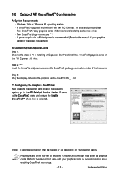
... manual that came with your graphics cards for more information about enabling CrossFireX technology. - 19 - Browse to the manual of the two cards. A CrossFireX-supported motherboard with sufficient power is recommended (Refer to the CrossFireX menu and ensure the Enable CrossFireXTM check box is selected. (Note) The bridge connectors may be...
... manual that came with your graphics cards for more information about enabling CrossFireX technology. - 19 - Browse to the manual of the two cards. A CrossFireX-supported motherboard with sufficient power is recommended (Refer to the CrossFireX menu and ensure the Enable CrossFireXTM check box is selected. (Note) The bridge connectors may be...
Manual
Page 20
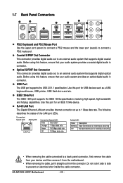
... (purple) to 1 Gbps data rate. Before using this feature, ensure that your audio system provides a coaxial digital audio in connector. GA-MA790X-UD3P Motherboard - 20 - Optical S/PDIF Out Connector This connector provides digital audio out to an external audio system that supports digital coaxial audio. Connection...When removing the cable connected to a back panel connector, first remove the cable from your device and then remove it from the motherboard. • When removing the cable, pull it side to side to an external audio system that supports digital optical audio. ...
... (purple) to 1 Gbps data rate. Before using this feature, ensure that your audio system provides a coaxial digital audio in connector. GA-MA790X-UD3P Motherboard - 20 - Optical S/PDIF Out Connector This connector provides digital audio out to an external audio system that supports digital coaxial audio. Connection...When removing the cable connected to a back panel connector, first remove the cable from your device and then remove it from the motherboard. • When removing the cable, pull it side to side to an external audio system that supports digital optical audio. ...
Manual
Page 22
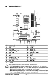
... sure to the connector on the motherboard. Unplug the power cord from the power outlet to prevent damage to the devices. • After installing the device and before connecting external devices: • First make sure the device cable has been securely attached to turn off the devices and your computer. GA-MA790X-UD3P Motherboard - 22 -
... sure to the connector on the motherboard. Unplug the power cord from the power outlet to prevent damage to the devices. • After installing the device and before connecting external devices: • First make sure the device cable has been securely attached to turn off the devices and your computer. GA-MA790X-UD3P Motherboard - 22 -
Manual
Page 23
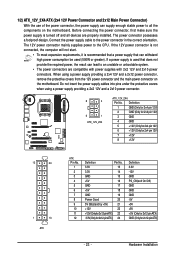
... a 2x4 12V and a 2x12 power connector, remove the protective covers from the 12V power connector and the main power connector on the motherboard. 1/2) ATX_12V_2X4/ATX (2x4 12V Power Connector and 2x12 Main Power Connector) With the use of the power connector, the power supply can... (Only for 2x12-pin ATX) GND (Only for 2x12-pin ATX) - 23 - If a power supply is turned off and all the components on the motherboard. When using a power supply providing a 2x2 12V and a 2x10 power connector. 8 4 5 1 ATX_12V_2X4 ATX_12V_2X4: Pin No. Hardware Installation Before connecting the ...
... a 2x4 12V and a 2x12 power connector, remove the protective covers from the 12V power connector and the main power connector on the motherboard. 1/2) ATX_12V_2X4/ATX (2x4 12V Power Connector and 2x12 Main Power Connector) With the use of the power connector, the power supply can... (Only for 2x12-pin ATX) GND (Only for 2x12-pin ATX) - 23 - If a power supply is turned off and all the components on the motherboard. When using a power supply providing a 2x2 12V and a 2x10 power connector. 8 4 5 1 ATX_12V_2X4 ATX_12V_2X4: Pin No. Hardware Installation Before connecting the ...
Manual
Page 24
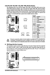
... typically designated by a stripe of a CPU fan with fan speed control design. The motherboard supports CPU fan speed control, which requires the use of different color. 33 1 34 2 GA-MA790X-UD3P Motherboard - 24 - Do not place a jumper cap on the headers. 6) FDD (Floppy... Disk Drive Connector) This connector is the ground wire). 3/4/5) CPU_FAN / SYS_FAN1 / SYS_FAN2 / PWR_FAN (Fan Headers) The motherboard has a 4-pin CPU fan header (CPU_FAN), ...
... typically designated by a stripe of a CPU fan with fan speed control design. The motherboard supports CPU fan speed control, which requires the use of different color. 33 1 34 2 GA-MA790X-UD3P Motherboard - 24 - Do not place a jumper cap on the headers. 6) FDD (Floppy... Disk Drive Connector) This connector is the ground wire). 3/4/5) CPU_FAN / SYS_FAN1 / SYS_FAN2 / PWR_FAN (Fan Headers) The motherboard has a 4-pin CPU fan header (CPU_FAN), ...
Manual
Page 26
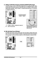
... operating. Pin No. Definition 1 MPD+ 2 MPD- 3 MPD- 1 System Status LED S0 On S1 Blinking S3/S4/S5 Off GA-MA790X-UD3P Motherboard - 26 - Please connect the L-shaped end of the SATA 3Gb/s cable to your SATA hard drive. 10) PWR_LED (System Power ...to SATA 3Gb/s standard and are compatible with SATA 1.5Gb/s standard. 9) GSATA2_0/1 (SATA 3Gb/s Connectors, Controlled by GIGABYTE SATA2, Purple) The SATA connectors conform to indicate system power status. The GIGABYTE SATA2 controller supports RAID 0 and RAID 1. Pin No. Definition 1 GND 2 TXP 3 TXN 1 7 GSATA2_0 GSATA2_1...
... operating. Pin No. Definition 1 MPD+ 2 MPD- 3 MPD- 1 System Status LED S0 On S1 Blinking S3/S4/S5 Off GA-MA790X-UD3P Motherboard - 26 - Please connect the L-shaped end of the SATA 3Gb/s cable to your SATA hard drive. 10) PWR_LED (System Power ...to SATA 3Gb/s standard and are compatible with SATA 1.5Gb/s standard. 9) GSATA2_0/1 (SATA 3Gb/s Connectors, Controlled by GIGABYTE SATA2, Purple) The SATA connectors conform to indicate system power status. The GIGABYTE SATA2 controller supports RAID 0 and RAID 1. Pin No. Definition 1 GND 2 TXP 3 TXN 1 7 GSATA2_0 GSATA2_1...


