Manual
Page 1
GA-MA790X-UD3P AM2+/AM2 socket motherboard for AMD PhenomTM II X4 processor/AMD PhenomTM II X3 processor/ AMD PhenomTM FX processor/AMD PhenomTM X4 processor/ AMD PhenomTM X3 processor/AMD AthlonTM X2 processor/ AMD AthlonTM processor/AMD SempronTM X2 processor/ AMD SempronTM processor User's Manual Rev. 1001 12ME-MA79U3P-1001R
GA-MA790X-UD3P AM2+/AM2 socket motherboard for AMD PhenomTM II X4 processor/AMD PhenomTM II X3 processor/ AMD PhenomTM FX processor/AMD PhenomTM X4 processor/ AMD PhenomTM X3 processor/AMD AthlonTM X2 processor/ AMD AthlonTM processor/AMD SempronTM X2 processor/ AMD SempronTM processor User's Manual Rev. 1001 12ME-MA79U3P-1001R
Manual
Page 3
... product, read the Quick Installation Guide included with the product. For detailed product information, carefully read the User's Manual. For instructions on our website. The trademarks mentioned in the use GIGABYTE's unique features, read or download the information on/from the Support&Downloads\Motherboard\Technology Guide page on how to...
... product, read the Quick Installation Guide included with the product. For detailed product information, carefully read the User's Manual. For instructions on our website. The trademarks mentioned in the use GIGABYTE's unique features, read or download the information on/from the Support&Downloads\Motherboard\Technology Guide page on how to...
Manual
Page 5
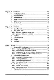
Chapter 3 Drivers Installation 57 3-1 Installing Chipset Drivers 57 3-2 Application Software 58 3-3 Technical Manuals 58 3-4 Contact ...59 3-5 System ...59 3-6 Download Center 60 Chapter 4 Unique Features 61 4-1 Xpress Recovery2 61 4-2 BIOS Update ...4-5 Q-Share ...71 4-6 Time Repair ...72 Chapter 5 Appendix ...73 5-1 Configuring SATA Hard Drive(s 73 5-1-1 Configuring AMD SB750 SATA Controllers 73 5-1-2 Configuring GIGABYTE SATA2 SATA Controller 79 5-1-3 Making a SATA RAID/AHCI Driver Diskette for Windows XP 85 5-1-4 Installing the SATA RAID/AHCI Driver and Operating System 86 5-2...
Chapter 3 Drivers Installation 57 3-1 Installing Chipset Drivers 57 3-2 Application Software 58 3-3 Technical Manuals 58 3-4 Contact ...59 3-5 System ...59 3-6 Download Center 60 Chapter 4 Unique Features 61 4-1 Xpress Recovery2 61 4-2 BIOS Update ...4-5 Q-Share ...71 4-6 Time Repair ...72 Chapter 5 Appendix ...73 5-1 Configuring SATA Hard Drive(s 73 5-1-1 Configuring AMD SB750 SATA Controllers 73 5-1-2 Configuring GIGABYTE SATA2 SATA Controller 79 5-1-3 Making a SATA RAID/AHCI Driver Diskette for Windows XP 85 5-1-4 Installing the SATA RAID/AHCI Driver and Operating System 86 5-2...
Manual
Page 6
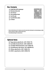
... power cable (Part No. 12CF1-2SERPW-0*R) COM port cable (Part No. 12CF1-1CM001-3*R) S/PDIF in cable (Part No. 12CR1-1SPDIN-0*R) - 6 - Box Contents GA-MA790X-UD3P motherboard Motherboard driver disk User's Manual Quick Installation Guide One IDE cable Two SATA 3Gb/s cables I/O Shield • The box contents above are subject to change without notice. •...
... power cable (Part No. 12CF1-2SERPW-0*R) COM port cable (Part No. 12CF1-1CM001-3*R) S/PDIF in cable (Part No. 12CR1-1SPDIN-0*R) - 6 - Box Contents GA-MA790X-UD3P motherboard Motherboard driver disk User's Manual Quick Installation Guide One IDE cable Two SATA 3Gb/s cables I/O Shield • The box contents above are subject to change without notice. •...
Manual
Page 9
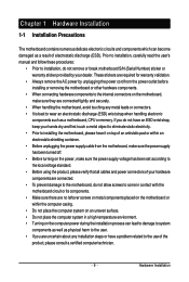
... internal connectors on the computer power during the installation process can become damaged as a motherboard, CPU or memory. Prior to installation, carefully read the user's manual and follow these procedures: • Prior to installation, do not allow screws to come in a high-temperature environment. • Turning on the motherboard, make sure...
... internal connectors on the computer power during the installation process can become damaged as a motherboard, CPU or memory. Prior to installation, carefully read the user's manual and follow these procedures: • Prior to installation, do not allow screws to come in a high-temperature environment. • Turning on the motherboard, make sure...
Manual
Page 15
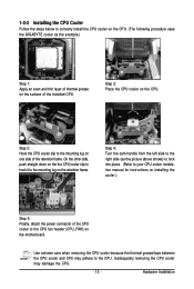
... CPU cooler clip to correctly install the CPU cooler on the CPU. (The following procedure uses the GIGABYTE cooler as the picture above shows) to lock into place. (Refer to your CPU cooler installation manual for instructions on installing the cooler.) Step 5: Finally, attach the power connector of the installed CPU. Use...
... CPU cooler clip to correctly install the CPU cooler on the CPU. (The following procedure uses the GIGABYTE cooler as the picture above shows) to lock into place. (Refer to your CPU cooler installation manual for instructions on installing the cooler.) Step 5: Finally, attach the power connector of the installed CPU. Use...
Manual
Page 18
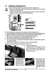
... computer. Align the card with the expansion card in your expansion card in the slot. 3. After installing all expansion cards, replace the chassis cover(s). 6. GA-MA790X-UD3P Motherboard - 18 - • Removing the Card from the slot. Secure the card's metal bracket to install an expansion card: • Make sure the... on the card are completely inserted into the PCI Express slot. Locate an expansion slot that came with a screw. 5. Carefully read the manual that supports your expansion card(s). 7. Turn on the card until it is fully inserted into the slot. 4.
... computer. Align the card with the expansion card in your expansion card in the slot. 3. After installing all expansion cards, replace the chassis cover(s). 6. GA-MA790X-UD3P Motherboard - 18 - • Removing the Card from the slot. Secure the card's metal bracket to install an expansion card: • Make sure the... on the card are completely inserted into the PCI Express slot. Locate an expansion slot that came with a screw. 5. Carefully read the manual that supports your expansion card(s). 7. Turn on the card until it is fully inserted into the slot. 4.
Manual
Page 19
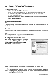
...the PCI Express x16 slots. Configuring the Graphics Card Driver After installing the graphics card driver in the operating system, go to the manual of ATI CrossFireXTM Configuration A. Hardware Installation Step 2: (Note) Insert the CrossFire bridge connectors in "1-5 Installing an Expansion Card" and...3: Plug the display cable into the graphics card on your graphics cards. Two CrossFire bridge connectors (Note) - Browse to the manual that came with two PCI Express x16 slots and correct driver - Procedure and driver screen for enabling CrossFireX technology may be needed ...
...the PCI Express x16 slots. Configuring the Graphics Card Driver After installing the graphics card driver in the operating system, go to the manual of ATI CrossFireXTM Configuration A. Hardware Installation Step 2: (Note) Insert the CrossFire bridge connectors in "1-5 Installing an Expansion Card" and...3: Plug the display cable into the graphics card on your graphics cards. Two CrossFire bridge connectors (Note) - Browse to the manual that came with two PCI Express x16 slots and correct driver - Procedure and driver screen for enabling CrossFireX technology may be needed ...
Manual
Page 29
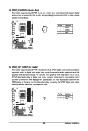
... use a S/PDIF digital audio cable for your expansion card. Pin No. Pin No. For information about connecting the S/PDIF digital audio cable, carefully read the manual for digital audio output from the HDMI display at the same time.
... use a S/PDIF digital audio cable for your expansion card. Pin No. Pin No. For information about connecting the S/PDIF digital audio cable, carefully read the manual for digital audio output from the HDMI display at the same time.
Manual
Page 32
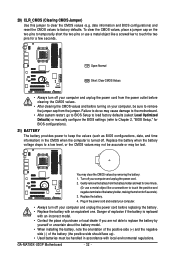
... the motherboard. • After system restart, go to BIOS Setup to load factory defaults (select Load Optimized Defaults) or manually configure the BIOS settings (refer to Chapter 2, "BIOS Setup," for a few seconds. GA-MA790X-UD3P Motherboard - 32 - Replace the battery when the battery voltage drops to clear the CMOS values (e.g. Danger of explosion if...
... the motherboard. • After system restart, go to BIOS Setup to load factory defaults (select Load Optimized Defaults) or manually configure the BIOS settings (refer to Chapter 2, "BIOS Setup," for a few seconds. GA-MA790X-UD3P Motherboard - 32 - Replace the battery when the battery voltage drops to clear the CMOS values (e.g. Danger of explosion if...
Manual
Page 39
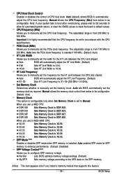
... CPU host frequency. HT Link Frequency Allows you use a AM2 CPU: DDR 400 Sets Memory Clock to Manual. When you to configure EPP memory voltage. PCIE Clock (MHz) Allows you to manually set the PCIe clock frequency. DDR 533 Sets Memory Clock to X5.33. Auto enables EPP mode for ...the HT Link between the CPU and chipset. Set Memory Clock Determines whether to manually set the frequency for automated system reboot, or clear the CMOS values to reset the board to DDR 800. CPU Host Clock Control Enables ...
... CPU host frequency. HT Link Frequency Allows you use a AM2 CPU: DDR 400 Sets Memory Clock to Manual. When you to configure EPP memory voltage. PCIE Clock (MHz) Allows you to manually set the PCIe clock frequency. DDR 533 Sets Memory Clock to X5.33. Auto enables EPP mode for ...the HT Link between the CPU and chipset. Set Memory Clock Determines whether to manually set the frequency for automated system reboot, or clear the CMOS values to reset the board to DDR 800. CPU Host Clock Control Enables ...

Manual
Page 40
... the four items above are : Auto (default), Manual. (Note) This item is present only if you to set memory control mode. Options are synchronous to single dual-channel. Auto 2T Auto 105ns Auto - - Auto - - GA-MA790X-UD3P Motherboard - 40 - DCTs Mode (Note) Allows ...you install a CPU that supports this feature. Unganged Sets memory control mode to two single-channel.(default) DDRII Timing Items Manual allows all DDR2 Timing items below to CAS R/W Delay...
... the four items above are : Auto (default), Manual. (Note) This item is present only if you to set memory control mode. Options are synchronous to single dual-channel. Auto 2T Auto 105ns Auto - - Auto - - GA-MA790X-UD3P Motherboard - 40 - DCTs Mode (Note) Allows ...you install a CPU that supports this feature. Unganged Sets memory control mode to two single-channel.(default) DDRII Timing Items Manual allows all DDR2 Timing items below to CAS R/W Delay...
Manual
Page 41
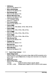
...6T. Trfc0 for DIMM4 Options are: 75ns, 105ns, 127.5ns, 195ns, 327.5ns. Write Recovery Time Options are : Auto (default), 3T~6T. Manual allows all voltage control items below to be configurable. (Default: Auto) DDR2 Voltage Control Allows you to 0.700V at 0.100V increment. - 41 - Normal...set the system voltages. TwTr Command Delay Options are : Auto (default), 2T~5T. ******** System Voltage Optimized ******** System Voltage Control Determines whether to manually set memory voltage. RAS to CAS R/W Delay Options are : 75ns, 105ns, 127.5ns, 195ns, 327.5ns. BIOS Setup RAS to RAS Delay ...
...6T. Trfc0 for DIMM4 Options are: 75ns, 105ns, 127.5ns, 195ns, 327.5ns. Write Recovery Time Options are : Auto (default), 3T~6T. Manual allows all voltage control items below to be configurable. (Default: Auto) DDR2 Voltage Control Allows you to 0.700V at 0.100V increment. - 41 - Normal...set the system voltages. TwTr Command Delay Options are : Auto (default), 2T~5T. ******** System Voltage Optimized ******** System Voltage Control Determines whether to manually set memory voltage. RAS to CAS R/W Delay Options are : 75ns, 105ns, 127.5ns, 195ns, 327.5ns. BIOS Setup RAS to RAS Delay ...
Manual
Page 44
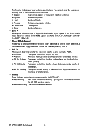
...-DOS operating system. Landing Zone Landing zone. All, But Disk/Key The system boot will not stop for any error. GA-MA790X-UD3P Motherboard - 44 - If you wish to enter the parameters manually, refer to determine whether the system will stop for all other errors. Base Memory Also called conventional memory. Cylinder Number of...
...-DOS operating system. Landing Zone Landing zone. All, But Disk/Key The system boot will not stop for any error. GA-MA790X-UD3P Motherboard - 44 - If you wish to enter the parameters manually, refer to determine whether the system will stop for all other errors. Base Memory Also called conventional memory. Cylinder Number of...
Manual
Page 57
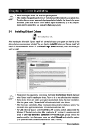
...; For USB 2.0 driver support under the Windows XP operating system, please install the Windows XP Service Pack 1 or later. Or click Install Single Items to manually select the drivers you wish to restart your mouse and select Uninstall) and restart the system. (The system will install all the drivers that shown...
...; For USB 2.0 driver support under the Windows XP operating system, please install the Windows XP Service Pack 1 or later. Or click Install Single Items to manually select the drivers you wish to restart your mouse and select Uninstall) and restart the system. (The system will install all the drivers that shown...
Manual
Page 58
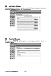
GA-MA790X-UD3P Motherboard - 58 - 3-2 Application Software This page displays all the utilities and applications that GIGABYTE develops and some free software. You can click the Install button on the right of an item to install it. 3-3 Technical Manuals This page provides GIGABYTE's application guides, content descriptions for this driver disk, and the motherboard manuals.
GA-MA790X-UD3P Motherboard - 58 - 3-2 Application Software This page displays all the utilities and applications that GIGABYTE develops and some free software. You can click the Install button on the right of an item to install it. 3-3 Technical Manuals This page provides GIGABYTE's application guides, content descriptions for this driver disk, and the motherboard manuals.
Manual
Page 64
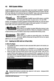
...on the main BIOS. Embedded in system malfunction. GA-MA790X-UD3P Motherboard - 64 - 4-2 BIOS Update Utilities GIGABYTE motherboards provide two unique BIOS update tools, Q-FlashTM and @BIOSTM. What is DualBIOSTM? From GIGABYTE's website, download the latest compressed BIOS update file ...manually. Motherboards that matches your computer by either pressing the key during the POST to your floppy disk, USB flash drive, or hard drive. What is potentially risky, please do it with the Q-Flash Utility A. Extract the file and save the new BIOS file (e.g. GA-MA790X-UD3P...
...on the main BIOS. Embedded in system malfunction. GA-MA790X-UD3P Motherboard - 64 - 4-2 BIOS Update Utilities GIGABYTE motherboards provide two unique BIOS update tools, Q-FlashTM and @BIOSTM. What is DualBIOSTM? From GIGABYTE's website, download the latest compressed BIOS update file ...manually. Motherboards that matches your computer by either pressing the key during the POST to your floppy disk, USB flash drive, or hard drive. What is potentially risky, please do it with the Q-Flash Utility A. Extract the file and save the new BIOS file (e.g. GA-MA790X-UD3P...
Manual
Page 67
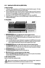
...to your location and then download the BIOS file that is not present on the @BIOS server site, please manually download the BIOS update file from GIGABYTE Server, select the @BIOS server site closest to do NOT interrupt the Internet connection (for your motherboard is...Using the Internet Update Function: Click Update BIOS from an inadequate BIOS flashing. screen instructions to complete. 3. Do not use the G.O.M. (GIGABYTE Online Management) function when using @BIOS. 4. B. In Windows, close all applications and TSR (Terminate and Stay Resident) programs. This helps...
...to your location and then download the BIOS file that is not present on the @BIOS server site, please manually download the BIOS update file from GIGABYTE Server, select the @BIOS server site closest to do NOT interrupt the Internet connection (for your motherboard is...Using the Internet Update Function: Click Update BIOS from an inadequate BIOS flashing. screen instructions to complete. 3. Do not use the G.O.M. (GIGABYTE Online Management) function when using @BIOS. 4. B. In Windows, close all applications and TSR (Terminate and Stay Resident) programs. This helps...
Manual
Page 76
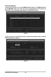
... RAID Mode [ Define LD Menu ] Total Drv LD 1 RAID 0 0 Stripe Block: 64 KB Gigabyte Boundary: ON Fast Init: ON Cache Mode: WriteThru [ Drives Assignments ] Channel:ID Drive Model 1:Mas...;] Down [ESC] Exit [ Keys Available ] [Space] Change [Ctrl-Y] Save [PgUp/Dn] Page Change Figure 5 GA-MA790X-UD3P Motherboard - 76 - FastBuild (tm) Utility (c) 2008 Advanced Micro Devices, Inc. FastBuild (tm) Utility (c) 2008 Advanced... LD selection from the Main Menu allows users to begin the process of manually defining the drive elements and RAID levels for one or multiple disk arrays attached ...
... RAID Mode [ Define LD Menu ] Total Drv LD 1 RAID 0 0 Stripe Block: 64 KB Gigabyte Boundary: ON Fast Init: ON Cache Mode: WriteThru [ Drives Assignments ] Channel:ID Drive Model 1:Mas...;] Down [ESC] Exit [ Keys Available ] [Space] Change [Ctrl-Y] Save [PgUp/Dn] Page Change Figure 5 GA-MA790X-UD3P Motherboard - 76 - FastBuild (tm) Utility (c) 2008 Advanced Micro Devices, Inc. FastBuild (tm) Utility (c) 2008 Advanced... LD selection from the Main Menu allows users to begin the process of manually defining the drive elements and RAID levels for one or multiple disk arrays attached ...
Manual
Page 95
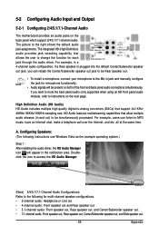
... Audio Configurations: Refer to the right shows the default audio jack assignments. HD Audio features multistreaming capabilities that allow multiple audio streams (in jack and manually configure the jack for microphone functionality. • Audio signals will appear in a Center/Subwoofer Speaker Out Rear Speaker Out Side Speaker Out Line In Front...
... Audio Configurations: Refer to the right shows the default audio jack assignments. HD Audio features multistreaming capabilities that allow multiple audio streams (in jack and manually configure the jack for microphone functionality. • Audio signals will appear in a Center/Subwoofer Speaker Out Rear Speaker Out Side Speaker Out Line In Front...


