Manual
Page 3
...the User's Manual. All rights reserved. Changes to use of this manual may be made by any form or by GIGABYTE without GIGABYTE's prior written permission. For instructions on your motherboard revision before updating motherboard BIOS, drivers, or when looking for technical information...prior notice. No part of GIGABYTE. Check your motherboard looks like this manual are legally registered to assist in this product, GIGABYTE provides the following types of documentations: For quick set-up of the product, read the Quick Installation Guide included with the product...
...the User's Manual. All rights reserved. Changes to use of this manual may be made by any form or by GIGABYTE without GIGABYTE's prior written permission. For instructions on your motherboard revision before updating motherboard BIOS, drivers, or when looking for technical information...prior notice. No part of GIGABYTE. Check your motherboard looks like this manual are legally registered to assist in this product, GIGABYTE provides the following types of documentations: For quick set-up of the product, read the Quick Installation Guide included with the product...
Manual
Page 4
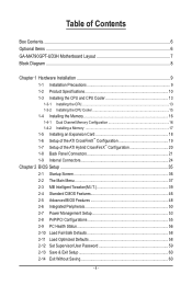
Table of Contents Box Contents...6 Optional Items...6 GA-MA790GPT-UD3H Motherboard Layout 7 Block Diagram...8 Chapter 1 Hardware Installation 9 1-1 Installation Precautions 9 1-2 Product Specifications 10 1-3 Installing the CPU and CPU Cooler 13 1-3-1 Installing the CPU 13 1-3-2 Installing the CPU Cooler 15 1-4 Installing the Memory 16 1-4-1 Dual Channel Memory Configuration 16 1-4-2 Installing a Memory 17 1-5 Installing an Expansion Card 18 1-6 Setup of the ATI CrossFireX™ Configuration...
Table of Contents Box Contents...6 Optional Items...6 GA-MA790GPT-UD3H Motherboard Layout 7 Block Diagram...8 Chapter 1 Hardware Installation 9 1-1 Installation Precautions 9 1-2 Product Specifications 10 1-3 Installing the CPU and CPU Cooler 13 1-3-1 Installing the CPU 13 1-3-2 Installing the CPU Cooler 15 1-4 Installing the Memory 16 1-4-1 Dual Channel Memory Configuration 16 1-4-2 Installing a Memory 17 1-5 Installing an Expansion Card 18 1-6 Setup of the ATI CrossFireX™ Configuration...
Manual
Page 5
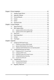
Chapter 3 Drivers Installation 61 3-1 Installing Chipset Drivers 61 3-2 Application Software 62 3-3 Technical Manuals 62 3-4 Contact...63 3-5 System...63 3-6 Download Center 64 Chapter 4 Unique Features 65 4-1 Xpress ...Repair...76 Chapter 5 Appendix...77 5-1 Configuring SATA Hard Drive(s 77 5-1-1 Configuring the Onboard SATA Controller 77 5-1-2 Making a SATA RAID/AHCI Driver Diskette 83 5-1-3 Installing the SATA RAID/AHCI Driver and Operating System 84 5-2 Configuring Audio Input and Output 88 5-2-1 Configuring 2/4/5.1/7.1-Channel Audio 88 5-2-2 Configuring S/PDIF In/Out 90 5-2-3...
Chapter 3 Drivers Installation 61 3-1 Installing Chipset Drivers 61 3-2 Application Software 62 3-3 Technical Manuals 62 3-4 Contact...63 3-5 System...63 3-6 Download Center 64 Chapter 4 Unique Features 65 4-1 Xpress ...Repair...76 Chapter 5 Appendix...77 5-1 Configuring SATA Hard Drive(s 77 5-1-1 Configuring the Onboard SATA Controller 77 5-1-2 Making a SATA RAID/AHCI Driver Diskette 83 5-1-3 Installing the SATA RAID/AHCI Driver and Operating System 84 5-2 Configuring Audio Input and Output 88 5-2-1 Configuring 2/4/5.1/7.1-Channel Audio 88 5-2-2 Configuring S/PDIF In/Out 90 5-2-3...
Manual
Page 6
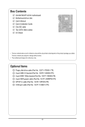
Box Contents GA-MA790GPT-UD3H motherboard Motherboard driver disk User's Manual Quick Installation Guide One IDE cable Two SATA 3Gb/s cables I/O Shield • The box contents above are subject to change without notice. • The motherboard image is ...
Box Contents GA-MA790GPT-UD3H motherboard Motherboard driver disk User's Manual Quick Installation Guide One IDE cable Two SATA 3Gb/s cables I/O Shield • The box contents above are subject to change without notice. • The motherboard image is ...

Manual
Page 8
... sure to x8 mode. The PCIEX8_1 slot shares bandwidth with a PCI Express graphics card, the PCIEX16_1 slot will operate at up to install it in the PCIEX16_1 slot. Block Diagram 1 PCI Express x16 (Note 1) 2 PCI Express x8 (Note 1) PCIe CLK (100 MHz) AM3 CPU CPU CLK+/- (200 MHz) ...
... sure to x8 mode. The PCIEX8_1 slot shares bandwidth with a PCI Express graphics card, the PCIEX16_1 slot will operate at up to install it in the PCIEX16_1 slot. Block Diagram 1 PCI Express x16 (Note 1) 2 PCI Express x8 (Note 1) PCIe CLK (100 MHz) AM3 CPU CPU CLK+/- (200 MHz) ...
Manual
Page 9
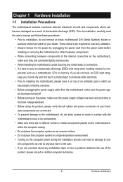
...not have an ESD wrist strap, keep your hands dry and first touch a metal object to eliminate static electricity. • Prior to installing the motherboard, please have it on top of an antistatic pad or within an electrostatic shielding container. • Before unplugging the power supply... cable from the power outlet before installing or removing the motherboard or other hardware components. • When connecting hardware components to the internal connectors on the computer power during ...
...not have an ESD wrist strap, keep your hands dry and first touch a metal object to eliminate static electricity. • Prior to installing the motherboard, please have it on top of an antistatic pad or within an electrostatic shielding container. • Before unplugging the power supply... cable from the power outlet before installing or removing the motherboard or other hardware components. • When connecting hardware components to the internal connectors on the computer power during ...
Manual
Page 10
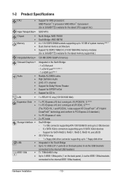
...Up to 3 IEEE 1394a ports (1 on the back panel, 6 via the IEEE 1394a brackets connected to the internal IEEE 1394a headers) Hardware Installation - 10 - 1-2 Product Specifications CPU Hyper Transport Bus Chipset Memory Intergrated Memory Onboard Graphics ...up to 16 GB of system memory (Note 1) Dual channel memory architecture Support for DDR3 1666(O.C.)/1333/1066 MHz memory modules (Go to GIGABYTE's website for the latest memory support list.) 128 MB DDR3 SidePort memory Integrated in the North Bridge: - 1 x D-Sub port -...
...Up to 3 IEEE 1394a ports (1 on the back panel, 6 via the IEEE 1394a brackets connected to the internal IEEE 1394a headers) Hardware Installation - 10 - 1-2 Product Specifications CPU Hyper Transport Bus Chipset Memory Intergrated Memory Onboard Graphics ...up to 16 GB of system memory (Note 1) Dual channel memory architecture Support for DDR3 1666(O.C.)/1333/1066 MHz memory modules (Go to GIGABYTE's website for the latest memory support list.) 128 MB DDR3 SidePort memory Integrated in the North Bridge: - 1 x D-Sub port -...
Manual
Page 11
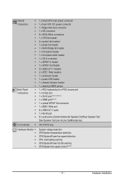
... temperature detection CPU/System/Power fan speed detection CPU overheating warning CPU/System/Power fan fail warning CPU/System fan speed control (Note 5) - 11 - Hardware Installation
... temperature detection CPU/System/Power fan speed detection CPU overheating warning CPU/System/Power fan fail warning CPU/System fan speed control (Note 5) - 11 - Hardware Installation

Manual
Page 12
... 2.0, SM BIOS 2.4, ACPI 1.0b Support for @BIOS Support for Q-Flash Support for Xpress BIOS Rescue Support for Download Center Support for Xpress Install Support for Xpress Recovery2 Support for EasyTune (Note 6) Support for Easy Energy Saver Support for Time Repair Support for Q-Share Norton Internet Security (OEM...size displayed will be sure to x8 mode. (Note 5) Whether the CPU/system fan speed control function is supported will operate at up to install it in EasyTune may differ by adapter. (Note 3) Simultaneous output for DVI-D and HDMI is not supported. (Note 4) For optimum performance,...
... 2.0, SM BIOS 2.4, ACPI 1.0b Support for @BIOS Support for Q-Flash Support for Xpress BIOS Rescue Support for Download Center Support for Xpress Install Support for Xpress Recovery2 Support for EasyTune (Note 6) Support for Easy Energy Saver Support for Time Repair Support for Q-Share Norton Internet Security (OEM...size displayed will be sure to x8 mode. (Note 5) Whether the CPU/system fan speed control function is supported will operate at up to install it in EasyTune may differ by adapter. (Note 3) Simultaneous output for DVI-D and HDMI is not supported. (Note 4) For optimum performance,...
Manual
Page 13
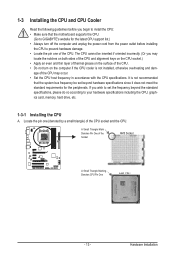
... even and thin layer of thermal grease on the computer if the CPU cooler is not recommended that the motherboard supports the CPU. (Go to GIGABYTE's website for the peripherals. age of the CPU. • Do not turn off the computer and unplug the power cord from the power outlet before... installing the CPU to prevent hardware damage. • Locate the pin one (denoted by a small triangle) of the Socket AM3 Socket A Small Triangle Marking Denotes CPU ...
... even and thin layer of thermal grease on the computer if the CPU cooler is not recommended that the motherboard supports the CPU. (Go to GIGABYTE's website for the peripherals. age of the CPU. • Do not turn off the computer and unplug the power cord from the power outlet before... installing the CPU to prevent hardware damage. • Locate the pin one (denoted by a small triangle) of the Socket AM3 Socket A Small Triangle Marking Denotes CPU ...
Manual
Page 14
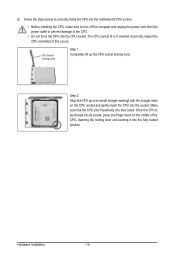
... Make sure that the CPU pins fit perfectly into the CPU socket. B. Follow the steps below to correctly install the CPU into the motherboard CPU socket. • Before installing the CPU, make sure to turn off the computer and unplug the power cord from the power outlet to ... and gently insert the CPU into the fully locked position. CPU Socket Locking Lever Step 1: Completely lift up the CPU socket locking lever. Hardware Installation - 14 - The CPU cannot fit in if oriented incorrectly. Once the CPU is positioned into its socket, place one (small triangle marking) ...
... Make sure that the CPU pins fit perfectly into the CPU socket. B. Follow the steps below to correctly install the CPU into the motherboard CPU socket. • Before installing the CPU, make sure to turn off the computer and unplug the power cord from the power outlet to ... and gently insert the CPU into the fully locked position. CPU Socket Locking Lever Step 1: Completely lift up the CPU socket locking lever. Hardware Installation - 14 - The CPU cannot fit in if oriented incorrectly. Once the CPU is positioned into its socket, place one (small triangle marking) ...
Manual
Page 15
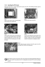
... CPU cooler on the CPU. (The following procedure uses the GIGABYTE cooler as the picture above shows) to lock into place. (Refer to your CPU cooler installation manual for instructions on installing the cooler.) Step 5: Finally, attach the power connector of the CPU cooler to the CPU fan header (CPU_FAN) on the motherboard... cooler may adhere to the right side (as the example.) Step 1: Apply an even and thin layer of thermal grease on one side of the installed CPU. Step 4: Turn the cam handle from the left side to the CPU. Step 3: Hook the CPU cooler clip to the mounting lug on the...
... CPU cooler on the CPU. (The following procedure uses the GIGABYTE cooler as the picture above shows) to lock into place. (Refer to your CPU cooler installation manual for instructions on installing the cooler.) Step 5: Finally, attach the power connector of the CPU cooler to the CPU fan header (CPU_FAN) on the motherboard... cooler may adhere to the right side (as the example.) Step 1: Apply an even and thin layer of thermal grease on one side of the installed CPU. Step 4: Turn the cam handle from the left side to the CPU. Step 3: Hook the CPU cooler clip to the mounting lug on the...
Manual
Page 16
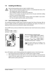
.... When enabling Dual Channel mode with two or four memory modules, it is installed. 2. The four DDR3 memory sockets are to be used . (Go to GIGABYTE's website for optimum performance. It is installed, the BIOS will double the original memory bandwidth. After the memory is recommended ...that memory of the same capacity, brand, speed, and chips be installed, it is recommended that memory of the ...
.... When enabling Dual Channel mode with two or four memory modules, it is installed. 2. The four DDR3 memory sockets are to be used . (Go to GIGABYTE's website for optimum performance. It is installed, the BIOS will double the original memory bandwidth. After the memory is recommended ...that memory of the same capacity, brand, speed, and chips be installed, it is recommended that memory of the ...
Manual
Page 17
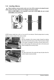
...the retaining clips at both ends of the socket will snap into the memory socket. Hardware Installation DDR3 and DDR2 DIMMs are not compatible to each other or DDR DIMMs. Be sure to install DDR3 DIMMs on the socket. Place the memory module on this motherboard. As indicated in ...the picture on the left, place your memory modules in one direction. Follow the steps below to the memory module. 1-4-2 Installing a Memory Before installing a memory module, make sure to turn off the computer and unplug the power cord from the power outlet to prevent damage to correctly...
...the retaining clips at both ends of the socket will snap into the memory socket. Hardware Installation DDR3 and DDR2 DIMMs are not compatible to each other or DDR DIMMs. Be sure to install DDR3 DIMMs on the socket. Place the memory module on this motherboard. As indicated in ...the picture on the left, place your memory modules in one direction. Follow the steps below to the memory module. 1-4-2 Installing a Memory Before installing a memory module, make sure to turn off the computer and unplug the power cord from the power outlet to prevent damage to correctly...
Manual
Page 18
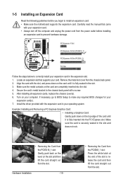
... with the expansion card in the slot. 3. Make sure the metal contacts on the card until it is securely seated in the expansion slot. 1. Hardware Installation - 18 - • Removing the Card from the PCIEX8_1 slot: Press the white latch at the end of the card until it is fully inserted into... not rock. • Removing the Card from the PCIEX16_1 slot: Gently push back on the lever on the top edge of the slot to correctly install your computer. Remove the metal slot cover from the slot. Secure the card's metal bracket to the chassis back panel with the slot, and press...
... with the expansion card in the slot. 3. Make sure the metal contacts on the card until it is securely seated in the expansion slot. 1. Hardware Installation - 18 - • Removing the Card from the PCIEX8_1 slot: Press the white latch at the end of the card until it is fully inserted into... not rock. • Removing the Card from the PCIEX16_1 slot: Gently push back on the lever on the top edge of the slot to correctly install your computer. Remove the metal slot cover from the slot. Secure the card's metal bracket to the chassis back panel with the slot, and press...
Manual
Page 19
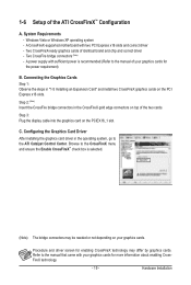
...driver - 1-6 Setup of identical brand and chip and correct driver - Procedure and driver screen for the power requirement) B. Hardware Installation Two CrossFire bridge connectors (Note) - Step 3: Plug the display cable into the graphics card on your graphics cards for enabling ... be needed or not depending on the PCIEX16_1 slot. Configuring the Graphics Card Driver After installing the graphics card driver in "1-5 Installing an Expansion Card" and install two CrossFireX graphics cards on top of your graphics cards. Two CrossFireX-ready graphics cards...
...driver - 1-6 Setup of identical brand and chip and correct driver - Procedure and driver screen for the power requirement) B. Hardware Installation Two CrossFire bridge connectors (Note) - Step 3: Plug the display cable into the graphics card on your graphics cards for enabling ... be needed or not depending on the PCIEX16_1 slot. Configuring the Graphics Card Driver After installing the graphics card driver in "1-5 Installing an Expansion Card" and install two CrossFireX graphics cards on top of your graphics cards. Two CrossFireX-ready graphics cards...

Manual
Page 20
... Buffer Size to disable the CrossFire function in the operating system, go to UMA+SidePort. (Note 3) - Configuring the Graphics Driver After installing the motherboard driver in the operating system first. Connecting the Graphics Cards Step 1: Observe the steps in - Set Internal Graphics Mode to ...the ATI Catalyst™ Control Center. Hardware Installation - 20 - C. Set Surround View to set the following items under the Advanced BIOS Features menu: - 1-7 Setup of the ATI Hybrid...
... Buffer Size to disable the CrossFire function in the operating system, go to UMA+SidePort. (Note 3) - Configuring the Graphics Driver After installing the motherboard driver in the operating system first. Connecting the Graphics Cards Step 1: Observe the steps in - Set Internal Graphics Mode to ...the ATI Catalyst™ Control Center. Hardware Installation - 20 - C. Set Surround View to set the following items under the Advanced BIOS Features menu: - 1-7 Setup of the ATI Hybrid...
Manual
Page 21
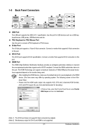
... formats. (AC3 and DTS require the use of 1920x1080p but the actual resolutions supported depend on the monitor being used. • After installing the HDMI device, make sure the default device for USB devices such as a USB keyboard/mouse, USB printer, USB flash drive and ...etc. Connect a monitor that supports DVI-D connection to transmit the uncompressed audio/video signals and is HDCP compliant. Hardware Installation The HDMI Technology can support a maximum resolution of an external decoder for decoding.) In Windows Vista, select Start>Control Panel>Sound, select...
... formats. (AC3 and DTS require the use of 1920x1080p but the actual resolutions supported depend on the monitor being used. • After installing the HDMI device, make sure the default device for USB devices such as a USB keyboard/mouse, USB printer, USB flash drive and ...etc. Connect a monitor that supports DVI-D connection to transmit the uncompressed audio/video signals and is HDCP compliant. Hardware Installation The HDMI Technology can support a maximum resolution of an external decoder for decoding.) In Windows Vista, select Start>Control Panel>Sound, select...

Manual
Page 22
...: Two 1 GB DDR3 1066 MHz memory modules with dual channel mode enabled • BIOS Setup: At least 256 MB of the LAN port LEDs. Hardware Installation - 22 -
...: Two 1 GB DDR3 1066 MHz memory modules with dual channel mode enabled • BIOS Setup: At least 256 MB of the LAN port LEDs. Hardware Installation - 22 -
Manual
Page 23
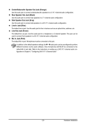
... drive, walkman, etc. In addition to the default speakers settings, the ~ audio jacks can be connected to the default Mic in a 4/5.1/7.1-channel audio configuration. Hardware Installation Use this audio jack for a headphone or 2-channel speaker. Refer to connect side speakers in jack. Rear Speaker Out Jack (Black) Use this audio jack...
... drive, walkman, etc. In addition to the default speakers settings, the ~ audio jacks can be connected to the default Mic in a 4/5.1/7.1-channel audio configuration. Hardware Installation Use this audio jack for a headphone or 2-channel speaker. Refer to connect side speakers in jack. Rear Speaker Out Jack (Black) Use this audio jack...


