Manual
Page 3
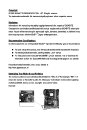
...motherboard looks like this manual are legally registered to use of GIGABYTE. No part of this product, GIGABYTE provides the following types of documentations: For quick set-up of the product, read the Quick Installation Guide included with the product. For detailed product... information, carefully read the User's Manual. For instructions on how to their respective owners. The trademarks mentioned in the use GIGABYTE's unique features, read or download ...
...motherboard looks like this manual are legally registered to use of GIGABYTE. No part of this product, GIGABYTE provides the following types of documentations: For quick set-up of the product, read the Quick Installation Guide included with the product. For detailed product... information, carefully read the User's Manual. For instructions on how to their respective owners. The trademarks mentioned in the use GIGABYTE's unique features, read or download ...

Manual
Page 4
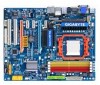
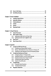
Table of Contents Box Contents ...6 Optional Items...6 GA-MA790GP-UD4H Motherboard Layout 7 Block Diagram...8 Chapter 1 Hardware Installation 9 1-1 Installation Precautions 9 1-2 Product Specifications 10 1-3 Installing the CPU and CPU Cooler 13 1-3-1 Installing the CPU 13 1-3-2 Installing the CPU Cooler 15 1-4 Installing the Memory 16 1-4-1 Dual Channel Memory Configuration 16 1-4-2 Installing a Memory 17 1-5 Installing an Expansion Card 18 1-6 Enabling the ATI Hybrid CrossFireXTM Function 19...
Table of Contents Box Contents ...6 Optional Items...6 GA-MA790GP-UD4H Motherboard Layout 7 Block Diagram...8 Chapter 1 Hardware Installation 9 1-1 Installation Precautions 9 1-2 Product Specifications 10 1-3 Installing the CPU and CPU Cooler 13 1-3-1 Installing the CPU 13 1-3-2 Installing the CPU Cooler 15 1-4 Installing the Memory 16 1-4-1 Dual Channel Memory Configuration 16 1-4-2 Installing a Memory 17 1-5 Installing an Expansion Card 18 1-6 Enabling the ATI Hybrid CrossFireXTM Function 19...
Manual
Page 5
2-13 Save & Exit Setup 58 2-14 Exit Without Saving 58 Chapter 3 Drivers Installation 59 3-1 Installing Chipset Drivers 59 3-2 Application Software 60 3-3 Technical Manuals 60 3-4 Contact ...61 3-5 System ...61 3-6 Download Center 62 Chapter 4 Unique ...Controller 75 5-1-2 Making a SATA RAID/AHCI Driver Diskette for W indows XP 81 5-1-3 Installing the SATA RAID/AHCI Driver and Operating System 82 5-2 Configuring AudioInput and Output 88 5-2-1 Configuring 2/4/5.1/7.1-Channel Audio 88 5-2-2 Installing the S/PDIF In and Out Cable (Optional 90 5-2-3 Enabling the Dolby Home Theater ...
2-13 Save & Exit Setup 58 2-14 Exit Without Saving 58 Chapter 3 Drivers Installation 59 3-1 Installing Chipset Drivers 59 3-2 Application Software 60 3-3 Technical Manuals 60 3-4 Contact ...61 3-5 System ...61 3-6 Download Center 62 Chapter 4 Unique ...Controller 75 5-1-2 Making a SATA RAID/AHCI Driver Diskette for W indows XP 81 5-1-3 Installing the SATA RAID/AHCI Driver and Operating System 82 5-2 Configuring AudioInput and Output 88 5-2-1 Configuring 2/4/5.1/7.1-Channel Audio 88 5-2-2 Installing the S/PDIF In and Out Cable (Optional 90 5-2-3 Enabling the Dolby Home Theater ...

Manual
Page 6
... No. 12CF1-2SERPW-0*R) COM port cable (Part No. 12CF1-1CM001-3*R) S/PDIF in and out cable (Part No. 12CR1-1SPINO-1*R) - 6 - Box Contents GA-MA790GP-UD4H motherboard Motherboard driver disk User's Manual Quick Installation Guide One IDE cable and one floppy disk drive cable Four SATA 3Gb/s cables 2-port USB 2.0 bracket I/O Shield • The box contents...
... No. 12CF1-2SERPW-0*R) COM port cable (Part No. 12CF1-1CM001-3*R) S/PDIF in and out cable (Part No. 12CR1-1SPINO-1*R) - 6 - Box Contents GA-MA790GP-UD4H motherboard Motherboard driver disk User's Manual Quick Installation Guide One IDE cable and one floppy disk drive cable Four SATA 3Gb/s cables 2-port USB 2.0 bracket I/O Shield • The box contents...
Manual
Page 8
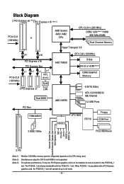
.... The PCIEX8_1 slot shares bandwidth with a PCI Express graphics card, the PCIEX16_1 slot will operate at up to install it in the PCIEX16__1 slot. Simultaneous output for DVI-D and HDMI is to be installed, be sure to x8 mode. - 8 - For optimum performance, if only one PCI Express graphics card is not supported...
.... The PCIEX8_1 slot shares bandwidth with a PCI Express graphics card, the PCIEX16_1 slot will operate at up to install it in the PCIEX16__1 slot. Simultaneous output for DVI-D and HDMI is to be installed, be sure to x8 mode. - 8 - For optimum performance, if only one PCI Express graphics card is not supported...

Manual
Page 9
...electrostatic discharge (ESD) wrist strap when handling electronic components such as a motherboard, CPU or memory. Hardware Installation Chapter 1 Hardware Installation 1-1 Installation Precautions The motherboard contains numerous delicate electronic circuits and components which can lead to damage to the local voltage... Turning on the motherboard, make sure they are connected tightly and securely. • When handling the motherboard, avoid touching any installation steps or have a problem related to the use of the product, please consult a certified computer technician. - 9 - These...
...electrostatic discharge (ESD) wrist strap when handling electronic components such as a motherboard, CPU or memory. Hardware Installation Chapter 1 Hardware Installation 1-1 Installation Precautions The motherboard contains numerous delicate electronic circuits and components which can lead to damage to the local voltage... Turning on the motherboard, make sure they are connected tightly and securely. • When handling the motherboard, avoid touching any installation steps or have a problem related to the use of the product, please consult a certified computer technician. - 9 - These...
Manual
Page 11
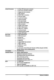
... (Note 6) BIOS 2 x 8 Mbit flash Use of licensed AWARD BIOS Support for DualBIOSTM PnP 1.0a, DMI 2.0, SM BIOS 2.4, ACPI 1.0b - 11 - Hardware Installation
... (Note 6) BIOS 2 x 8 Mbit flash Use of licensed AWARD BIOS Support for DualBIOSTM PnP 1.0a, DMI 2.0, SM BIOS 2.4, ACPI 1.0b - 11 - Hardware Installation
Manual
Page 12
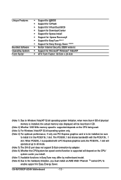
... For optimum performance, if only one PCI Express graphics card is installed, the actual memory size displayed will depend on the CPU/ system cooler you install. (Note 7) Available functions in the PCIEX16_1 slot. Unique Features Bundled...Install Support for Xpress Recovery2 Support for EasyTune (Note 7) Support for Easy Energy Saver (Note 8) Norton Internet Security (OEM version) Support for Microsoft® Windows® Vista/XP ATX Form Factor; 30.5cm x 24.4cm (Note 1) Due to enable support for Easy Energy Saver. GA-MA790GP-UD4H...
... For optimum performance, if only one PCI Express graphics card is installed, the actual memory size displayed will depend on the CPU/ system cooler you install. (Note 7) Available functions in the PCIEX16_1 slot. Unique Features Bundled...Install Support for Xpress Recovery2 Support for EasyTune (Note 7) Support for Easy Energy Saver (Note 8) Norton Internet Security (OEM version) Support for Microsoft® Windows® Vista/XP ATX Form Factor; 30.5cm x 24.4cm (Note 1) Due to enable support for Easy Energy Saver. GA-MA790GP-UD4H...

Manual
Page 13
... grease on the surface of the CPU. • Do not turn off the computer and unplug the power cord from the power outlet before installing the CPU to GIGABYTE's website for the peripherals. mended that the motherboard supports the CPU. (Go to prevent hardware damage. • Locate the pin one (denoted by...
... grease on the surface of the CPU. • Do not turn off the computer and unplug the power cord from the power outlet before installing the CPU to GIGABYTE's website for the peripherals. mended that the motherboard supports the CPU. (Go to prevent hardware damage. • Locate the pin one (denoted by...

Manual
Page 14
... their holes. Step 2: Align the CPU pin one finger down on the CPU socket and gently insert the CPU into the motherboard CPU socket. GA-MA790GP-UD4H Motherboard - 14 - Before installing the CPU, make sure to turn off the computer and unplug the power cord from the power outlet to prevent damage to correctly... install the CPU into the socket. Once the CPU is positioned into its socket, place one (small triangle marking) with the triangle mark on the middle ...
... their holes. Step 2: Align the CPU pin one finger down on the CPU socket and gently insert the CPU into the motherboard CPU socket. GA-MA790GP-UD4H Motherboard - 14 - Before installing the CPU, make sure to turn off the computer and unplug the power cord from the power outlet to prevent damage to correctly... install the CPU into the socket. Once the CPU is positioned into its socket, place one (small triangle marking) with the triangle mark on the middle ...

Manual
Page 15
... mounting lug on the CPU. Hardware Installation Step 2: Place the CPU cooler on one side of the retention frame. 1-3-2 Installing the CPU Cooler Follow the steps below to correctly install the CPU cooler on the CPU. (The following procedure uses the GIGABYTE cooler as the picture above shows)... to lock into place. (Refer to your CPU cooler installation manual for instructions on installing the cooler.) Step 5: Finally, attach the...
... mounting lug on the CPU. Hardware Installation Step 2: Place the CPU cooler on one side of the retention frame. 1-3-2 Installing the CPU Cooler Follow the steps below to correctly install the CPU cooler on the CPU. (The following procedure uses the GIGABYTE cooler as the picture above shows)... to lock into place. (Refer to your CPU cooler installation manual for instructions on installing the cooler.) Step 5: Finally, attach the...

Manual
Page 16
...GIGABYTE's website for optimum performance. 1-4 Installing the Memory Read the following guidelines before you are unable to insert the memory, switch the direction. 1-4-1 Dual Channel Memory Configuration This motherboard provides four DDR2 memory sockets and supports Dual Channel Technology. Dual Channel mode cannot be used and installed in the DDR2_1 and DDR2_2 sockets. GA-MA790GP-UD4H... Motherboard - 16 - After the memory is recommended that memory of the memory. If you begin to install the ...
...GIGABYTE's website for optimum performance. 1-4 Installing the Memory Read the following guidelines before you are unable to insert the memory, switch the direction. 1-4-1 Dual Channel Memory Configuration This motherboard provides four DDR2 memory sockets and supports Dual Channel Technology. Dual Channel mode cannot be used and installed in the DDR2_1 and DDR2_2 sockets. GA-MA790GP-UD4H... Motherboard - 16 - After the memory is recommended that memory of the memory. If you begin to install the ...

Manual
Page 17
... the memory module is securely inserted. - 17 - Place the memory module on this motherboard. Step 2: The clips at both ends of the memory socket. Hardware Installation Step 1: Note the orientation of the memory, push down on the memory and insert it can only fit in the memory sockets... , make sure to turn off the computer and unplug the power cord from the power outlet to prevent damage to install DDR2 DIMMs on the socket. Follow the steps below to correctly install your fingers on the top edge of the memory module. As indicated in the picture on the left, place...
... the memory module is securely inserted. - 17 - Place the memory module on this motherboard. Step 2: The clips at both ends of the memory socket. Hardware Installation Step 1: Note the orientation of the memory, push down on the memory and insert it can only fit in the memory sockets... , make sure to turn off the computer and unplug the power cord from the power outlet to prevent damage to install DDR2 DIMMs on the socket. Follow the steps below to correctly install your fingers on the top edge of the memory module. As indicated in the picture on the left, place...

Manual
Page 18
...with the slot, and press down on the card until it is fully inserted into the slot. 4. GA-MA790GP-UD4H Motherboard - 18 - 1-5 Installing an Expansion Card Read the following guidelines before installing an expansion card to prevent hardware damage. Align the card with the expansion card in the slot. 3.... inserted into the PCI Express slot. Locate an expansion slot that came with a screw. 5. Secure the card's metal bracket to correctly install your expansion card. • Always turn off the computer and unplug the power cord from the chassis back panel. 2. PCI Express x1...
...with the slot, and press down on the card until it is fully inserted into the slot. 4. GA-MA790GP-UD4H Motherboard - 18 - 1-5 Installing an Expansion Card Read the following guidelines before installing an expansion card to prevent hardware damage. Align the card with the expansion card in the slot. 3.... inserted into the PCI Express slot. Locate an expansion slot that came with a screw. 5. Secure the card's metal bracket to correctly install your expansion card. • Always turn off the computer and unplug the power cord from the chassis back panel. 2. PCI Express x1...
Manual
Page 19
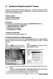
...Hybrid CrossFireXTM Function Combining the onboard GPU with a discrete graphics card, ATI Hybrid CrossFireX can provide significantly advanced display performance for installation. B. Follow the steps below to enter the Catalyst Control Center. Step 1: The ATI icon appears in the operating system first...• Set Init Display First to disable the CrossFire function in the system tray after the system restarts. Hardware Installation Graphics Card Requirement: An ATI Hybrid CrossFireX-supported graphics card. This section give instructions on configuring an ATI Hybrid ...
...Hybrid CrossFireXTM Function Combining the onboard GPU with a discrete graphics card, ATI Hybrid CrossFireX can provide significantly advanced display performance for installation. B. Follow the steps below to enter the Catalyst Control Center. Step 1: The ATI icon appears in the operating system first...• Set Init Display First to disable the CrossFire function in the system tray after the system restarts. Hardware Installation Graphics Card Requirement: An ATI Hybrid CrossFireX-supported graphics card. This section give instructions on configuring an ATI Hybrid ...
Manual
Page 20
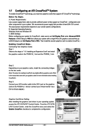
..., you need two graphics cards that provides at least 20A 12V current. We recommend a power supply that support ATI CrossFireTM technology. GA-MA790GP-UD4H Motherboard - 20 - C. Step 2: Depending on your overall system configurations. B. Refer to the manual that is able to provide ...). Before You Begin-A. Supported Operating Systems: Windows Vista and Windows XP. The exact power requirements depend on your graphics cards, install the connecting bridges on the PCIEX16_1 slot (or connect your system. Power Requirements: Use a power supply that came with a single...
..., you need two graphics cards that provides at least 20A 12V current. We recommend a power supply that support ATI CrossFireTM technology. GA-MA790GP-UD4H Motherboard - 20 - C. Step 2: Depending on your overall system configurations. B. Refer to the manual that is able to provide ...). Before You Begin-A. Supported Operating Systems: Windows Vista and Windows XP. The exact power requirements depend on your graphics cards, install the connecting bridges on the PCIEX16_1 slot (or connect your system. Power Requirements: Use a power supply that came with a single...

Manual
Page 21
Refer the figures below for details.), and enter BIOS Setup, then set the Default device for sound playback is HDCP compliant. Hardware Installation In Windows Vista, select Start>Control Panel> Sound, select Realtek HDMI Output and then click Set Default. - 21 - HDMI Port The...channel-LPCM formats. (AC3 and DTS require the use of 1920x1080p but the actual resolutions supported depend on the monitor being used. • After installing the HDMI device, make sure the default device for sound playback to this port. DVI-D Port The DVI-D port supports DVI-D specifictation. Connect...
Refer the figures below for details.), and enter BIOS Setup, then set the Default device for sound playback is HDCP compliant. Hardware Installation In Windows Vista, select Start>Control Panel> Sound, select Realtek HDMI Output and then click Set Default. - 21 - HDMI Port The...channel-LPCM formats. (AC3 and DTS require the use of 1920x1080p but the actual resolutions supported depend on the monitor being used. • After installing the HDMI device, make sure the default device for sound playback to this port. DVI-D Port The DVI-D port supports DVI-D specifictation. Connect...

Manual
Page 23
... audio jack to the default Mic in jack ( ). Only microphones still MUST be connected to prevent an electrical short inside the cable connector. - 23 - Hardware Installation Line Out Jack (Green) The default line out jack. Mic In Jack (Pink) The default Mic in devices such as an optical drive, walkman, etc...
... audio jack to the default Mic in jack ( ). Only microphones still MUST be connected to prevent an electrical short inside the cable connector. - 23 - Hardware Installation Line Out Jack (Green) The default line out jack. Mic In Jack (Pink) The default Mic in devices such as an optical drive, walkman, etc...

Manual
Page 24
GA-MA790GP-UD4H Motherboard - 24 - Unplug the power cord from the power outlet to prevent damage to the devices. • After installing the device and before connecting external devices: • First make sure the device cable has been securely attached to the connector on the computer..., make sure your devices are compliant with the connectors you wish to connect. • Before installing the devices, be sure to turn off the devices and your computer. 1-9 Internal Connectors 13 2 6 7 13 11 14 4 15 16 20 9 18 8 ...
GA-MA790GP-UD4H Motherboard - 24 - Unplug the power cord from the power outlet to prevent damage to the devices. • After installing the device and before connecting external devices: • First make sure the device cable has been securely attached to the connector on the computer..., make sure your devices are compliant with the connectors you wish to connect. • Before installing the devices, be sure to turn off the devices and your computer. 1-9 Internal Connectors 13 2 6 7 13 11 14 4 15 16 20 9 18 8 ...

Manual
Page 25
...on the motherboard. When using a power supply providing a 2x2 12V and a 2x10 power connector. 5 8 1 4 ATX_12V_2X4 ATX_12V_2X4: Pin No. The power connector possesses a foolproof design. Hardware Installation The 12V power connector mainly supplies power to the power connector in the correct orientation. 1/2) ATX_12V_2X4/ATX (2x4 12V Power Connector and 2x12 Main Power...) With the use of the power connector, the power supply can lead to an unstable or unbootable system. • The power connectors are properly installed. Connect the power supply cable to the CPU.
...on the motherboard. When using a power supply providing a 2x2 12V and a 2x10 power connector. 5 8 1 4 ATX_12V_2X4 ATX_12V_2X4: Pin No. The power connector possesses a foolproof design. Hardware Installation The 12V power connector mainly supplies power to the power connector in the correct orientation. 1/2) ATX_12V_2X4/ATX (2x4 12V Power Connector and 2x12 Main Power...) With the use of the power connector, the power supply can lead to an unstable or unbootable system. • The power connectors are properly installed. Connect the power supply cable to the CPU.


