
Manual
Page 1
GA-MA790FX-DQ6 AM2+/AM2 socket motherboard for AMD PhenomTM FX processor/ AMD PhenomTM processor/ AMD AthlonTM 64 FX processor/ AMD AthlonTM 64 X2 Dual-Core processor/ AMD AthlonTM 64 processor/AMD SempronTM processor User's Manual Rev. 1003 12ME-MA79FX6-1003R
GA-MA790FX-DQ6 AM2+/AM2 socket motherboard for AMD PhenomTM FX processor/ AMD PhenomTM processor/ AMD AthlonTM 64 FX processor/ AMD AthlonTM 64 X2 Dual-Core processor/ AMD AthlonTM 64 processor/AMD SempronTM processor User's Manual Rev. 1003 12ME-MA79FX6-1003R

Manual
Page 2
Motherboard GA-MA790FX-DQ6 Sept. 28, 2007 Motherboard GA-MA790FX-DQ6 Sept. 28, 2007
Motherboard GA-MA790FX-DQ6 Sept. 28, 2007 Motherboard GA-MA790FX-DQ6 Sept. 28, 2007

Manual
Page 3
...legally registered to the specifications and features in the use GIGABYTE's unique features, read or download the information on/from the Support\Motherboard\Technology Guide page on your motherboard revision before updating motherboard BIOS, drivers, or when looking for technical information. ...translated, transmitted, or published in this product, GIGABYTE provides the following types of documentations: „ For quick set-up of the motherboard is exclusively licensed to use of GIGABYTE. No part of GIGABYTE branded motherboards. by GIGA-BYTE TECHNOLOGY CO., LTD as ...
...legally registered to the specifications and features in the use GIGABYTE's unique features, read or download the information on/from the Support\Motherboard\Technology Guide page on your motherboard revision before updating motherboard BIOS, drivers, or when looking for technical information. ...translated, transmitted, or published in this product, GIGABYTE provides the following types of documentations: „ For quick set-up of the motherboard is exclusively licensed to use of GIGABYTE. No part of GIGABYTE branded motherboards. by GIGA-BYTE TECHNOLOGY CO., LTD as ...
Manual
Page 4
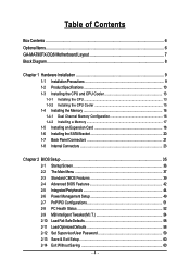
Table of Contents Box Contents ...6 OptionalItems ...6 GA-MA790FX-DQ6 Motherboard Layout 7 Block Diagram ...8 Chapter 1 Hardware Installation 9 1-1 Installation Precautions 9 1-2 Product Specifications 10 1-3 Installing the CPU and CPU Cooler 13 1-3-1 Installing the CPU 13 1-3-2 Installing the CPU ...
Table of Contents Box Contents ...6 OptionalItems ...6 GA-MA790FX-DQ6 Motherboard Layout 7 Block Diagram ...8 Chapter 1 Hardware Installation 9 1-1 Installation Precautions 9 1-2 Product Specifications 10 1-3 Installing the CPU and CPU Cooler 13 1-3-1 Installing the CPU 13 1-3-2 Installing the CPU ...

Manual
Page 6
.... 12CF1-2SERPW-01R) S/PDIF in cable (Part No. 12CR1-1SPDIN-01R) LPT port cable (Part No. 12CF1-1LP001-01R) - 6 - Box Contents GA-MA790FX-DQ6 motherboard Motherboard driver disk User's Manual Quick Installation Guide One IDE cable and one floppy disk drive cable Four SATA 3Gb/s cables One SATA bracket I/O Shield •...; The box contents above are subject to change without notice. • The motherboard image is for reference only and the actual items shall depend on product package you obtain. The box contents are for reference only.
.... 12CF1-2SERPW-01R) S/PDIF in cable (Part No. 12CR1-1SPDIN-01R) LPT port cable (Part No. 12CF1-1LP001-01R) - 6 - Box Contents GA-MA790FX-DQ6 motherboard Motherboard driver disk User's Manual Quick Installation Guide One IDE cable and one floppy disk drive cable Four SATA 3Gb/s cables One SATA bracket I/O Shield •...; The box contents above are subject to change without notice. • The motherboard image is for reference only and the actual items shall depend on product package you obtain. The box contents are for reference only.

Manual
Page 7
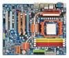
GA-MA790FX-DQ6 Motherboard Layout KB_MS OPTICAL ATX_12V_2X CPU_FAN Socket AM2 COMA COAXIAL ATX V1394 USB_LAN1 PWR_FAN USB_LAN2 USB_ESATA GA-MA790FX-DQ6 AUDIO RTL8111B F_AUDIO RTL8111B PCIE_1 PCIE_16_A NB_FAN GIGABYTE SATA2 PCIE_8_A SPDIF_IN CODEC PCIE_8_B CD_IN SPDIF_OUT PCIE_16_B TSB43AB23 PCI1 PCI2 F2_1394 SYS_FAN2 AMD 790FX DDRII_1 DDRII_2 DDRII_3 DDRII_4 IDE FDD CLR_CMOS AMD SB600 BATTERY ...
GA-MA790FX-DQ6 Motherboard Layout KB_MS OPTICAL ATX_12V_2X CPU_FAN Socket AM2 COMA COAXIAL ATX V1394 USB_LAN1 PWR_FAN USB_LAN2 USB_ESATA GA-MA790FX-DQ6 AUDIO RTL8111B F_AUDIO RTL8111B PCIE_1 PCIE_16_A NB_FAN GIGABYTE SATA2 PCIE_8_A SPDIF_IN CODEC PCIE_8_B CD_IN SPDIF_OUT PCIE_16_B TSB43AB23 PCI1 PCI2 F2_1394 SYS_FAN2 AMD 790FX DDRII_1 DDRII_2 DDRII_3 DDRII_4 IDE FDD CLR_CMOS AMD SB600 BATTERY ...

Manual
Page 9
...when handling electronic components such as a result of electrostatic discharge (ESD). Hardware Installation English Chapter 1 Hardware Installation 1-1 Installation Precautions The motherboard contains numerous delicate electronic circuits and components which can lead to damage to system components as well as physical harm to the user....wrist strap, keep your hands dry and first touch a metal object to eliminate static electricity. • Prior to installing the motherboard, please have it on top of an antistatic pad or within the computer casing. • Do not place the computer ...
...when handling electronic components such as a result of electrostatic discharge (ESD). Hardware Installation English Chapter 1 Hardware Installation 1-1 Installation Precautions The motherboard contains numerous delicate electronic circuits and components which can lead to damage to system components as well as physical harm to the user....wrist strap, keep your hands dry and first touch a metal object to eliminate static electricity. • Prior to installing the motherboard, please have it on top of an antistatic pad or within the computer casing. • Do not place the computer ...

Manual
Page 10
...4 SATA 3Gb/s devices - TSB43AB23 chip Up to 3 IEEE 1394a ports (1 on the back panel supporting up to the internal IEEE 1394a headers) GA-MA790FX-DQ6 Motherboard - 10 - English 1-2 Product Specifications CPU Š Hyper Transport Bus Š Chipset Š Š Memory Š Š Š...3Gb/s connectors (SATAII0, SATAII1, SATAII2, SATAII3) supporting up to 1 floppy disk drive T.I. Support for SATA RAID 0, RAID 1 and RAID 0+1 2 x GIGABYTE SATA2 chip: - 2 x SATA 3Gb/s connectors (GSATAII_1, GSATAII_2) supporting up to 2 SATA 3Gb/s devices - 2 x eSATA 3Gb/s ports on the back...
...4 SATA 3Gb/s devices - TSB43AB23 chip Up to 3 IEEE 1394a ports (1 on the back panel supporting up to the internal IEEE 1394a headers) GA-MA790FX-DQ6 Motherboard - 10 - English 1-2 Product Specifications CPU Š Hyper Transport Bus Š Chipset Š Š Memory Š Š Š...3Gb/s connectors (SATAII0, SATAII1, SATAII2, SATAII3) supporting up to 1 floppy disk drive T.I. Support for SATA RAID 0, RAID 1 and RAID 0+1 2 x GIGABYTE SATA2 chip: - 2 x SATA 3Gb/s connectors (GSATAII_1, GSATAII_2) supporting up to 2 SATA 3Gb/s devices - 2 x eSATA 3Gb/s ports on the back...

Manual
Page 12
... Express graphics card(s), be less than 4 GB of a CPU that supports ECC is required if you wish to 0.45V with 1 MHz increment - GA-MA790FX-DQ6 Motherboard - 12 - Increase Chipset voltage by 0.05V to install ECC memory. (Note 4) If you are installed, the PCIE_16_A and PCIE_16_B slots will operate... is supported will be sure to install it/them in the PCIE_16_A or/and PCIE_16_B slot(s) for optimum performance. Increase FSB voltage by motherboard model. (Note 7) The adjustable CPU voltage range depends on the CPU being used. (Note 3) Use of physical memory is supported ...
... Express graphics card(s), be less than 4 GB of a CPU that supports ECC is required if you wish to 0.45V with 1 MHz increment - GA-MA790FX-DQ6 Motherboard - 12 - Increase Chipset voltage by 0.05V to install ECC memory. (Note 4) If you are installed, the PCIE_16_A and PCIE_16_B slots will operate... is supported will be sure to install it/them in the PCIE_16_A or/and PCIE_16_B slot(s) for optimum performance. Increase FSB voltage by motherboard model. (Note 7) The adjustable CPU voltage range depends on the CPU being used. (Note 3) Use of physical memory is supported ...

Manual
Page 13
.... • Apply an even and thin layer of thermal grease on the computer if the CPU cooler is not recom- mended that the motherboard supports the CPU. (Go to GIGABYTE's website for the peripherals. Locate the pin one of the CPU. A Small Triangle Mark Denotes Pin One of the Socket AM2 CPU...
.... • Apply an even and thin layer of thermal grease on the computer if the CPU cooler is not recom- mended that the motherboard supports the CPU. (Go to GIGABYTE's website for the peripherals. Locate the pin one of the CPU. A Small Triangle Mark Denotes Pin One of the Socket AM2 CPU...

Manual
Page 14
... sure to turn off the computer and unplug the power cord from the power outlet to prevent damage to correctly install the CPU into the motherboard CPU socket. Make sure that the CPU pins fit perfectly into the CPU socket. Do not force the CPU into their holes. Once the CPU... into the socket. Step 2: Align the CPU pin one finger down on the CPU socket and gently insert the CPU into the fully locked position. GA-MA790FX-DQ6 Motherboard - 14 - Adjust the CPU orientation if this occurs. English B. Follow the steps below to the CPU.
... sure to turn off the computer and unplug the power cord from the power outlet to prevent damage to correctly install the CPU into the motherboard CPU socket. Make sure that the CPU pins fit perfectly into the CPU socket. Do not force the CPU into their holes. Once the CPU... into the socket. Step 2: Align the CPU pin one finger down on the CPU socket and gently insert the CPU into the fully locked position. GA-MA790FX-DQ6 Motherboard - 14 - Adjust the CPU orientation if this occurs. English B. Follow the steps below to the CPU.

Manual
Page 15
English 1-3-2 Installing the CPU Cooler Follow the steps below to correctly install the CPU cooler on the CPU. (The following procedure uses the GIGABYTE cooler as the picture above shows) to lock into place. (Refer to your CPU cooler installation manual for instructions on installing the cooler.) Step 5: ...cam handle from the left side to the right side (as the example.) Step 1: Apply an even and thin layer of thermal grease on the motherboard. Inadequately removing the CPU cooler may adhere to the mounting lug on the CPU. Step 2: Place the CPU cooler on one side of the ...
English 1-3-2 Installing the CPU Cooler Follow the steps below to correctly install the CPU cooler on the CPU. (The following procedure uses the GIGABYTE cooler as the picture above shows) to lock into place. (Refer to your CPU cooler installation manual for instructions on installing the cooler.) Step 5: ...cam handle from the left side to the right side (as the example.) Step 1: Apply an even and thin layer of thermal grease on the motherboard. Inadequately removing the CPU cooler may adhere to the mounting lug on the CPU. Step 2: Place the CPU cooler on one side of the ...

Manual
Page 16
...- Dual Channel mode cannot be enabled if only one direction. GA-MA790FX-DQ6 Motherboard - 16 - A memory module can be installed in only one DDR2 memory module is recommended that memory of the same capacity, brand, speed, and chips be used . (Go to GIGABYTE's website for optimum performance. DS/SS DS/SS Four Modules ...is recommended that you install them in Dual Channel mode. 1. After the memory is recommended that the motherboard supports the memory. DDRII_1 DDRII_2 DDRII_3 DDRII_4 Due to insert the memory, switch the direction. 1-4-1 Dual Channel Memory Configuration This...
...- Dual Channel mode cannot be enabled if only one direction. GA-MA790FX-DQ6 Motherboard - 16 - A memory module can be installed in only one DDR2 memory module is recommended that memory of the same capacity, brand, speed, and chips be used . (Go to GIGABYTE's website for optimum performance. DS/SS DS/SS Four Modules ...is recommended that you install them in Dual Channel mode. 1. After the memory is recommended that the motherboard supports the memory. DDRII_1 DDRII_2 DDRII_3 DDRII_4 Due to insert the memory, switch the direction. 1-4-1 Dual Channel Memory Configuration This...

Manual
Page 17
... the power outlet to prevent damage to correctly install your fingers on the top edge of the memory module. Place the memory module on this motherboard. DDR2 DIMMs are not compatible to DDR DIMMs. Be sure to install DDR2 DIMMs on the socket.
... the power outlet to prevent damage to correctly install your fingers on the top edge of the memory module. Place the memory module on this motherboard. DDR2 DIMMs are not compatible to DDR DIMMs. Be sure to install DDR2 DIMMs on the socket.

Manual
Page 18
..., replace the chassis cover(s). 6. Example: Installing and Removing a PCI Express x16 Graphics Card: • Installing a Graphics Card: Gently insert the graphics card into the slot. 4. GA-MA790FX-DQ6 Motherboard - 18 - English 1-5 Installing an Expansion Card Read the following guidelines before installing an expansion card to make any required BIOS changes for your operating system...
..., replace the chassis cover(s). 6. Example: Installing and Removing a PCI Express x16 Graphics Card: • Installing a Graphics Card: Gently insert the graphics card into the slot. 4. GA-MA790FX-DQ6 Motherboard - 18 - English 1-5 Installing an Expansion Card Read the following guidelines before installing an expansion card to make any required BIOS changes for your operating system...

Manual
Page 19
When you install two graphics cards, connect the power cable from the slot. • The motherboard provides a PCIE_12V power connector, which can supply extra power to this connector. - 19 - Hardware Installation English • Removing the Card (PCIE_16_A, PCIE_16_B slots): Gently push ...
When you install two graphics cards, connect the power cable from the slot. • The motherboard provides a PCIE_12V power connector, which can supply extra power to this connector. - 19 - Hardware Installation English • Removing the Card (PCIE_16_A, PCIE_16_B slots): Gently push ...

Manual
Page 20
... connector on the bracket. English 1-6 Installing the SATA Bracket The SATA bracket allows you only need to connect the SATA signal cable. GA-MA790FX-DQ6 Motherboard - 20 - the external SATA con- nector on Step 5: the bracket. Connect the other ends of the external enclosure. Follow the... bracket includes one SATA bracket, one SATA signal cable, and one free PCI slot and secure the SATA bracket to your motherboard. Step 2: Connect the SATA cable from the bracket SATA signal cable into the corresponding connectors when installing. Before connecting the SATA...
... connector on the bracket. English 1-6 Installing the SATA Bracket The SATA bracket allows you only need to connect the SATA signal cable. GA-MA790FX-DQ6 Motherboard - 20 - the external SATA con- nector on Step 5: the bracket. Connect the other ends of the external enclosure. Follow the... bracket includes one SATA bracket, one SATA signal cable, and one free PCI slot and secure the SATA bracket to your motherboard. Step 2: Connect the SATA cable from the bracket SATA signal cable into the corresponding connectors when installing. Before connecting the SATA...

Manual
Page 21
... and etc. • When removing the cable connected to a back panel connector, first remove the cable from your device and then remove it from the motherboard. • When removing the cable, pull it side to side to connect devices such as a mouse, modem or other peripherals. Use this feature, ensure that...
... and etc. • When removing the cable connected to a back panel connector, first remove the cable from your device and then remove it from the motherboard. • When removing the cable, pull it side to side to connect devices such as a mouse, modem or other peripherals. Use this feature, ensure that...

Manual
Page 22
... supported by the GIGABYTE SATA2 chip conforms to connect an external SATA device or a SATA port multiplier. Use this audio jack to connect side speakers in a 5.1/7.1-channel audio configuration. Only microphones still MUST be reconfigured to connect rear speakers in devices such as an optical drive, walkman, etc. GA-MA790FX-DQ6 Motherboard - 22 - Use the...
... supported by the GIGABYTE SATA2 chip conforms to connect an external SATA device or a SATA port multiplier. Use this audio jack to connect side speakers in a 5.1/7.1-channel audio configuration. Only microphones still MUST be reconfigured to connect rear speakers in devices such as an optical drive, walkman, etc. GA-MA790FX-DQ6 Motherboard - 22 - Use the...

Manual
Page 23
... devices and your devices are compliant with the connectors you wish to connect. • Before installing the devices, be sure to the connector on the motherboard. - 23 -
... devices and your devices are compliant with the connectors you wish to connect. • Before installing the devices, be sure to the connector on the motherboard. - 23 -


