Manual
Page 3
... use GIGABYTE's unique features, read the User's Manual. Documentation Classifications In order to the specifications and features in this : "REV: X.X." Changes to assist in any form or by GIGABYTE without GIGABYTE's prior written permission. For detailed product information, carefully read or download the information on/from the Support&Downloads\Motherboard\Technology Guide page on your motherboard revision before updating motherboard BIOS, drivers, or when looking for technical information. For instructions...
... use GIGABYTE's unique features, read the User's Manual. Documentation Classifications In order to the specifications and features in this : "REV: X.X." Changes to assist in any form or by GIGABYTE without GIGABYTE's prior written permission. For detailed product information, carefully read or download the information on/from the Support&Downloads\Motherboard\Technology Guide page on your motherboard revision before updating motherboard BIOS, drivers, or when looking for technical information. For instructions...
Manual
Page 4
.../GA-MA785GMT-UD2H(US2H 7 Motherboard Layout...7 Block Diagram...8 Chapter 1 Hardware Installation 9 1-1 Installation Precautions 9 1-2 Product Specifications 10 1-3 Installing the CPU and CPU Cooler 13 1-3-1 Installing the CPU 13 1-3-2 Installing the CPU Cooler 15 1-4 Installing the Memory 16 1-4-1 Dual Channel Memory Configuration 16 1-4-2 Installing a Memory 17 1-5 Installing an Expansion Card 18 1-6 Setup of the ATI Hybrid CrossFireX™ Configuration 19 1-7 Back Panel Connectors 20 1-8 Internal Connectors 23 Chapter 2 BIOS Setup 35 2-1 Startup Screen 36 2-2 The Main Menu...
.../GA-MA785GMT-UD2H(US2H 7 Motherboard Layout...7 Block Diagram...8 Chapter 1 Hardware Installation 9 1-1 Installation Precautions 9 1-2 Product Specifications 10 1-3 Installing the CPU and CPU Cooler 13 1-3-1 Installing the CPU 13 1-3-2 Installing the CPU Cooler 15 1-4 Installing the Memory 16 1-4-1 Dual Channel Memory Configuration 16 1-4-2 Installing a Memory 17 1-5 Installing an Expansion Card 18 1-6 Setup of the ATI Hybrid CrossFireX™ Configuration 19 1-7 Back Panel Connectors 20 1-8 Internal Connectors 23 Chapter 2 BIOS Setup 35 2-1 Startup Screen 36 2-2 The Main Menu...
Manual
Page 5
...k Only for GA-MA785GPMT-UD2H. Chapter 3 Drivers Installation 61 3-1 Installing Chipset Drivers 61 3-2 Application Software 62 3-3 Technical Manuals 62 3-4 Contact...63 3-5 System...63 3-6 Download Center 64 Chapter 4 Unique Features 65 4-1 Xpress Recovery2 65 4-2 BIOS Update Utilities 68 4-2-1 Updating the BIOS with the Q-Flash Utility 68 4-2-2 Updating the BIOS with the @BIOS Utility 71 4-3 EasyTune 6...72 4-4 Easy Energy Saver 73 4-5 Q-Share...75 4-6 Time Repair...76 Chapter 5 Appendix...77 5-1 Configuring SATA Hard Drive(s 77 5-1-1 Configuring the Onboard SATA Controller 77...
...k Only for GA-MA785GPMT-UD2H. Chapter 3 Drivers Installation 61 3-1 Installing Chipset Drivers 61 3-2 Application Software 62 3-3 Technical Manuals 62 3-4 Contact...63 3-5 System...63 3-6 Download Center 64 Chapter 4 Unique Features 65 4-1 Xpress Recovery2 65 4-2 BIOS Update Utilities 68 4-2-1 Updating the BIOS with the Q-Flash Utility 68 4-2-2 Updating the BIOS with the @BIOS Utility 71 4-3 EasyTune 6...72 4-4 Easy Energy Saver 73 4-5 Q-Share...75 4-6 Time Repair...76 Chapter 5 Appendix...77 5-1 Configuring SATA Hard Drive(s 77 5-1-1 Configuring the Onboard SATA Controller 77...
Manual
Page 10
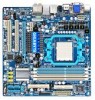
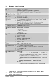
Only for GA-MA785GPMT-UD2H. Hardware Installation - 10 - Only for GA-MA785GMT-UD2H. 1-2 Product Specifications CPU Support for AM3 processors: AMD Phenom™ II processor/ AMD Athlon™ II processor (Go to GIGABYTE's website for the latest CPU support list.) Hyper Transport Bus 5200 MT/s Chipset Memory North Bridge: AMD 785G South Bridge: AMD SB710 4 x 1.5V DDR3 DIMM sockets supporting up to 16 GB of system memory (Note 1) Dual channel memory architecture Support for DDR3...
Only for GA-MA785GPMT-UD2H. Hardware Installation - 10 - Only for GA-MA785GMT-UD2H. 1-2 Product Specifications CPU Support for AM3 processors: AMD Phenom™ II processor/ AMD Athlon™ II processor (Go to GIGABYTE's website for the latest CPU support list.) Hyper Transport Bus 5200 MT/s Chipset Memory North Bridge: AMD 785G South Bridge: AMD SB710 4 x 1.5V DDR3 DIMM sockets supporting up to 16 GB of system memory (Note 1) Dual channel memory architecture Support for DDR3...
Manual
Page 19
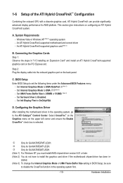
Step 2: Plug the display cable into the onboard graphics port on the PCI Express slot. BIOS Setup Enter BIOS Setup to the ATI Catalyst™ Control Center. D. Configuring the Graphics Driver After installing the motherboard driver in the operating system, go to set the following items under the Advanced BIOS Features menu: - k Only for GA-MA785GPMT-UD2H. Windows Vista or Windows XP (Note 1) operating system - C. Set Internal Graphics Mode to 256MB or 512MB. (Note 3) - Set UMA Frame Buffer Size to UMA.kl(Note 3) - An ATI Hybrid...
Step 2: Plug the display cable into the onboard graphics port on the PCI Express slot. BIOS Setup Enter BIOS Setup to the ATI Catalyst™ Control Center. D. Configuring the Graphics Driver After installing the motherboard driver in the operating system, go to set the following items under the Advanced BIOS Features menu: - k Only for GA-MA785GPMT-UD2H. Windows Vista or Windows XP (Note 1) operating system - C. Set Internal Graphics Mode to 256MB or 512MB. (Note 3) - Set UMA Frame Buffer Size to UMA.kl(Note 3) - An ATI Hybrid...

Manual
Page 25
...headers. - 25 - Most fans are designed with color-coded power connector wires. The black connector wire is the ground wire. When connecting a fan cable, be installed inside the chassis. Most fans are not configuration jumper blocks. Overheating may hang. • These fan headers are designed with colorcoded power connector wires. Pin No. 3/4) CPU_FAN/SYS_FAN (Fan Headers) The motherboard has a 4-pin CPU fan header (CPU_FAN)and a 4-pin system fan header(SYS_FAN). The motherboard supports CPU fan speed control, which requires the use of a CPU fan with fan speed control...
...headers. - 25 - Most fans are designed with color-coded power connector wires. The black connector wire is the ground wire. When connecting a fan cable, be installed inside the chassis. Most fans are not configuration jumper blocks. Overheating may hang. • These fan headers are designed with colorcoded power connector wires. Pin No. 3/4) CPU_FAN/SYS_FAN (Fan Headers) The motherboard has a 4-pin CPU fan header (CPU_FAN)and a 4-pin system fan header(SYS_FAN). The motherboard supports CPU fan speed control, which requires the use of a CPU fan with fan speed control...
Manual
Page 36
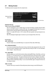
... entering BIOS Setup. In Boot Menu, use the up hard drive data using the driver disk, the key can access Boot Menu again to change it to continue IDE mode operation and stop showing this message again. After system restart, the device boot order will display a message during the POST. BIOS Setup - 36 - Press to enable AHCI mode or to AHCI mode and enable hot plug functionality for one time only. To exit Boot Menu, press . The system will appear again at IDE MODE!" Motherboard Model BIOS Version Award Modular BIOS...
... entering BIOS Setup. In Boot Menu, use the up hard drive data using the driver disk, the key can access Boot Menu again to change it to continue IDE mode operation and stop showing this message again. After system restart, the device boot order will display a message during the POST. BIOS Setup - 36 - Press to enable AHCI mode or to AHCI mode and enable hot plug functionality for one time only. To exit Boot Menu, press . The system will appear again at IDE MODE!" Motherboard Model BIOS Version Award Modular BIOS...

Manual
Page 38
... clock, frequency and voltages of your CPU, memory, etc. Standard CMOS Features Use this menu to configure the system time and date, hard drive types, floppy disk drive types, and the type of errors that stop the system boot, etc. Advanced BIOS Features Use this menu to configure the device boot order, advanced features available on the CPU, and the primary display adapter. Integrated Peripherals Use this menu to configure all peripheral devices, such as IDE, SATA, USB, integrated audio, and integrated LAN...
... clock, frequency and voltages of your CPU, memory, etc. Standard CMOS Features Use this menu to configure the system time and date, hard drive types, floppy disk drive types, and the type of errors that stop the system boot, etc. Advanced BIOS Features Use this menu to configure the device boot order, advanced features available on the CPU, and the primary display adapter. Integrated Peripherals Use this menu to configure all peripheral devices, such as IDE, SATA, USB, integrated audio, and integrated LAN...
Manual
Page 43
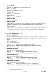
... the memory. Normal Supplies the South Bridge voltage as required. Trfc3 for GA-MA785GPMT-UD2H. - 43 - Row Cycle Time Options are : Auto (default), 4T~7T. Auto lets the BIOS automatically set memory voltage. NorthBridge Volt Control Allows you to 0.3V at 0.1V increment. j Only for DIMM4 Options are: Auto (default), 90ns, 110ns, 160ns, 300ns, 350ns. Manual allows all voltage control items below to be configurable. (Default: Manual) DDR3 Voltage Control Allows you to manually set the South Bridge voltage. Enabled...
... the memory. Normal Supplies the South Bridge voltage as required. Trfc3 for GA-MA785GPMT-UD2H. - 43 - Row Cycle Time Options are : Auto (default), 4T~7T. Auto lets the BIOS automatically set memory voltage. NorthBridge Volt Control Allows you to 0.3V at 0.1V increment. j Only for DIMM4 Options are: Auto (default), 90ns, 110ns, 160ns, 300ns, 350ns. Manual allows all voltage control items below to be configurable. (Default: Manual) DDR3 Voltage Control Allows you to manually set the South Bridge voltage. Enabled...
Manual
Page 47
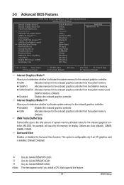
... memory. (Default) Disabled Disables the onboard graphics controller. This option is configurable only if an ATI graphics card is the total amount of system memory allocated solely for example, will use only this feature. - 47 - 2-5 Advanced BIOS Features CMOS Setup Utility-Copyright (C) 1984-2009 Award Software Advanced BIOS Features Internal Graphics Mode j Internal Graphics Mode kl UMA Frame Buffer Size x Surround View Onboard VGA output connect AMD C1E Support (Note) Virtualization Patch AMD TLB Erratum (Note) AMD K8 Cool&Quiet control } Hard Disk Boot...
... memory. (Default) Disabled Disables the onboard graphics controller. This option is configurable only if an ATI graphics card is the total amount of system memory allocated solely for example, will use only this feature. - 47 - 2-5 Advanced BIOS Features CMOS Setup Utility-Copyright (C) 1984-2009 Award Software Advanced BIOS Features Internal Graphics Mode j Internal Graphics Mode kl UMA Frame Buffer Size x Surround View Onboard VGA output connect AMD C1E Support (Note) Virtualization Patch AMD TLB Erratum (Note) AMD K8 Cool&Quiet control } Hard Disk Boot...

Manual
Page 48
.... Options are: Floppy, LS120, Hard Disk, CDROM, ZIP, USB-FDD, USB-ZIP, USB-CDROM, USB-HDD, Legacy LAN, Disabled. Hard Disk Boot Priority Specifies the sequence of the hard drive and to which port the display device is installed. (Default: Enabled) (Note) This item appears only if you enter BIOS Setup. Capability Enables or disables the S.M.A.R.T. (Self Monitoring and Reporting Technology) capability of your system to report read/write errors of loading the operating system from your computer and its power consumption. (Default) Disabled Disables this menu...
.... Options are: Floppy, LS120, Hard Disk, CDROM, ZIP, USB-FDD, USB-ZIP, USB-CDROM, USB-HDD, Legacy LAN, Disabled. Hard Disk Boot Priority Specifies the sequence of the hard drive and to which port the display device is installed. (Default: Enabled) (Note) This item appears only if you enter BIOS Setup. Capability Enables or disables the S.M.A.R.T. (Self Monitoring and Reporting Technology) capability of your system to report read/write errors of loading the operating system from your computer and its power consumption. (Default) Disabled Disables this menu...

Manual
Page 50
...hot plug. 2-6 Integrated Peripherals CMOS Setup Utility-Copyright (C) 1984-2009 Award Software Integrated Peripherals OnChip IDE Channel OnChip SATA Controller OnChip SATA Type x OnChip SATA Port4/5 Type Onboard LAN Function Onboard LAN Boot ROM } SMART LAN Onboard Audio Function Onboard 1394 Function OnChip USB Controller USB EHCI Controller USB Keyboard Support USB Mouse Support Legacy USB storage detect Onboard Serial Port 1 Onboard Parallel Port Parallel Port Mode x ECP Mode Use DMA [Enabled] [Enabled] [Native IDE] IDE [Enabled] [Disabled...
...hot plug. 2-6 Integrated Peripherals CMOS Setup Utility-Copyright (C) 1984-2009 Award Software Integrated Peripherals OnChip IDE Channel OnChip SATA Controller OnChip SATA Type x OnChip SATA Port4/5 Type Onboard LAN Function Onboard LAN Boot ROM } SMART LAN Onboard Audio Function Onboard 1394 Function OnChip USB Controller USB EHCI Controller USB Keyboard Support USB Mouse Support Legacy USB storage detect Onboard Serial Port 1 Onboard Parallel Port Parallel Port Mode x ECP Mode Use DMA [Enabled] [Enabled] [Native IDE] IDE [Enabled] [Disabled...

Manual
Page 52
... if Parallel Port Mode is set this item to Disabled. USB EHCI Controller Enables or disables the integrated USB 2.0 controller. (Default: Enabled) USB Keyboard Support Allows USB keyboard to be used in MS-DOS. (Default: Enabled) USB Mouse Support Allows USB mouse to be used in ECP mode. BIOS Setup - 52 - Onboard 1394 Function Enables or disables the onboard IEEE 1394 function. (Default: Enabled) OnChip USB Controller Enables or disables the integrated USB controller. (Default: Enabled) Disabled will turn off all of using the onboard audio, set to ECP or ECP+EPP mode. Options are : SPP...
... if Parallel Port Mode is set this item to Disabled. USB EHCI Controller Enables or disables the integrated USB 2.0 controller. (Default: Enabled) USB Keyboard Support Allows USB keyboard to be used in MS-DOS. (Default: Enabled) USB Mouse Support Allows USB mouse to be used in ECP mode. BIOS Setup - 52 - Onboard 1394 Function Enables or disables the onboard IEEE 1394 function. (Default: Enabled) OnChip USB Controller Enables or disables the integrated USB controller. (Default: Enabled) Disabled will turn off all of using the onboard audio, set to ECP or ECP+EPP mode. Options are : SPP...

Manual
Page 53
... system appears to be awakened from an ACPI sleep state by a wake-up signal from a modem that supports wake-up function. (Default: Disabled) (Note) Supported on Suspend) sleep state. Press and hold the power button for less than in the S1 state. 2-7 Power Management Setup CMOS Setup Utility-Copyright (C) 1984-2009 Award Software Power Management Setup ACPI Suspend Type Soft-Off by Power button USB Wake Up from the installed USB device. (Default: Enabled) Modem Ring Resume Allows the system to...
... system appears to be awakened from an ACPI sleep state by a wake-up signal from a modem that supports wake-up function. (Default: Disabled) (Note) Supported on Suspend) sleep state. Press and hold the power button for less than in the S1 state. 2-7 Power Management Setup CMOS Setup Utility-Copyright (C) 1984-2009 Award Software Power Management Setup ACPI Suspend Type Soft-Off by Power button USB Wake Up from the installed USB device. (Default: Enabled) Modem Ring Resume Allows the system to...
Manual
Page 68
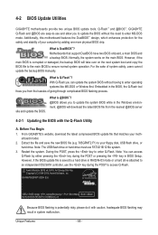
... your motherboard model. 2. Normally, the system works on the next system boot and copy the BIOS file to the main BIOS to access Q-Flash. However, if the main BIOS is saved to a hard drive in RAID/AHCI mode or a hard drive attached to an independent IDE/SATA controller, use the key during the POST or pressing the key in the Windows environment. @BIOS will take over on the main BIOS. Before You Begin 1. Restart the system. However, if the BIOS update file is...
... your motherboard model. 2. Normally, the system works on the next system boot and copy the BIOS file to the main BIOS to access Q-Flash. However, if the main BIOS is saved to a hard drive in RAID/AHCI mode or a hard drive attached to an independent IDE/SATA controller, use the key during the POST or pressing the key in the Windows environment. @BIOS will take over on the main BIOS. Before You Begin 1. Restart the system. However, if the BIOS update file is...

Manual
Page 77
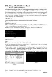
... Attach one hard drive. • An empty formatted floppy disk. • Windows Vista/XP setup disk. • Motherboard driver disk. 5-1-1 Configuring the Onboard SATA Controller A. C. Appendix Then connect the power connector from your computer. Before you begin Please prepare: • At least two SATA hard drives (to ensure optimal performance, it is set to create RAID, you use two hard drives with identical model and capacity). Configure a RAID array in BIOS Setup. If you do not want to AHCI or RAID mode. - 77...
... Attach one hard drive. • An empty formatted floppy disk. • Windows Vista/XP setup disk. • Motherboard driver disk. 5-1-1 Configuring the Onboard SATA Controller A. C. Appendix Then connect the power connector from your computer. Before you begin Please prepare: • At least two SATA hard drives (to ensure optimal performance, it is set to create RAID, you use two hard drives with identical model and capacity). Configure a RAID array in BIOS Setup. If you do not want to AHCI or RAID mode. - 77...
Manual
Page 83
... RAID/AHCI mode, you wish to copy the Windows 64-bit driver. - 83 - Figure 2 Figure 3 (Note) Change the directory from the motherboard driver disk to a USB flash drive. For installing Windows Vista, you also can copy the SATA controller driver from \x86 to \x64 if you need to install the SATA controller driver during the Windows setup process. See the instructions below about how to exit when finished. Steps: 1: Boot from the menu and press . Press any key...
... RAID/AHCI mode, you wish to copy the Windows 64-bit driver. - 83 - Figure 2 Figure 3 (Note) Change the directory from the motherboard driver disk to a USB flash drive. For installing Windows Vista, you also can copy the SATA controller driver from \x86 to \x64 if you need to install the SATA controller driver during the Windows setup process. See the instructions below about how to exit when finished. Steps: 1: Boot from the menu and press . Press any key...
Manual
Page 84
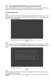
... return to configure a SCSI Adapter for use with the Windows XP installation. AMD AHCI Compatible RAID Controller-x86 platform AMD AHCI Compatible RAID Controller-x64 platform ENTER=Select F3=Exit Step 3: Figure 2 On the next screen, press to specify additional device. 5-1-3 Installing the SATA RAID/AHCI Driver and Operating System With the SATA RAID/AHCI driver diskette and correct BIOS settings, you are examples of Windows XP and Vista installation. ceed with Windows, using a device support disk provided by an adapter manufacturer. A. Then a controller menu similar to...
... return to configure a SCSI Adapter for use with the Windows XP installation. AMD AHCI Compatible RAID Controller-x86 platform AMD AHCI Compatible RAID Controller-x64 platform ENTER=Select F3=Exit Step 3: Figure 2 On the next screen, press to specify additional device. 5-1-3 Installing the SATA RAID/AHCI Driver and Operating System With the SATA RAID/AHCI driver diskette and correct BIOS settings, you are examples of Windows XP and Vista installation. ceed with Windows, using a device support disk provided by an adapter manufacturer. A. Then a controller menu similar to...
Manual
Page 88
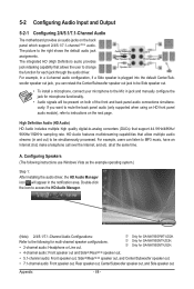
... plugged into the default Center/Sub- The integrated HD (High Definition) audio provides jack retasking capability that support 44.1KHz/48KHz/ 96KHz/192KHz sampling rate. High Definition Audio (HD Audio) HD Audio includes multiple high quality digital-to the following instructions use Windows Vista as the example operating system.) Step 1: After installing the audio driver, the HD Audio Manager icon will be simultaneously processed. Configuring Speakers (The following for GA-MA785GPMT-UD2H...
... plugged into the default Center/Sub- The integrated HD (High Definition) audio provides jack retasking capability that support 44.1KHz/48KHz/ 96KHz/192KHz sampling rate. High Definition Audio (HD Audio) HD Audio includes multiple high quality digital-to the following instructions use Windows Vista as the example operating system.) Step 1: After installing the audio driver, the HD Audio Manager icon will be simultaneously processed. Configuring Speakers (The following for GA-MA785GPMT-UD2H...
Manual
Page 96
...the instructions on the motherboard battery in Device Manager or Sound, video, and game controllers. A: The following Award BIOS beep code descriptions may help you identify possible computer problems. (For reference only.) 1 short: System boots successfully 1 long, 3 short: Keyboard error 2 short: CMOS setting error 1 long, 9 short: BIOS ROM error 1 long, 1 short: Memory or motherboard error Continuous long beeps: Graphics card not inserted properly 1 long, 2 short: Monitor or graphics card error Continuous short beeps: Power error Appendix - 96 - A: Some advanced options are...
...the instructions on the motherboard battery in Device Manager or Sound, video, and game controllers. A: The following Award BIOS beep code descriptions may help you identify possible computer problems. (For reference only.) 1 short: System boots successfully 1 long, 3 short: Keyboard error 2 short: CMOS setting error 1 long, 9 short: BIOS ROM error 1 long, 1 short: Memory or motherboard error Continuous long beeps: Graphics card not inserted properly 1 long, 2 short: Monitor or graphics card error Continuous short beeps: Power error Appendix - 96 - A: Some advanced options are...


