Manual
Page 1
GA-MA785GPMT-UD2H/ GA-MA785GMT-UD2H/ GA-MA785GMT-US2H AM3 socket motherboard for AMD Phenom™ II processor/ AMD Athlon™ II processor User's Manual Rev. 1101 12ME-MA785T2-1101R
GA-MA785GPMT-UD2H/ GA-MA785GMT-UD2H/ GA-MA785GMT-US2H AM3 socket motherboard for AMD Phenom™ II processor/ AMD Athlon™ II processor User's Manual Rev. 1101 12ME-MA785T2-1101R
Manual
Page 2
Motherboard GA-MA785GPMT-UD2H/GA-MA785GMT-UD2H/GA-MA785GMT-US2H July 16, 2009 Motherboard GA-MA785GPMT-UD2H/ GA-MA785GMT-UD2H/ GA-MA785GMT-US2H July 16, 2009
Motherboard GA-MA785GPMT-UD2H/GA-MA785GMT-UD2H/GA-MA785GMT-US2H July 16, 2009 Motherboard GA-MA785GPMT-UD2H/ GA-MA785GMT-UD2H/ GA-MA785GMT-US2H July 16, 2009
Manual
Page 3
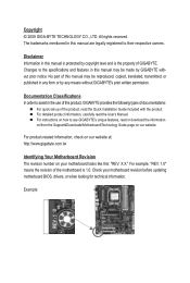
..., copied, translated, transmitted, or published in the use GIGABYTE's unique features, read or download the information on/from the Support&Downloads\Motherboard\Technology Guide page on your motherboard revision before updating motherboard BIOS, drivers, or when looking for technical information. For... Quick Installation Guide included with the product. For product-related information, check on our website at: http://www.gigabyte.com.tw Identifying Your Motherboard Revision The revision number on our website. All rights reserved. Copyright © 2009 GIGA-BYTE TECHNOLOGY CO., LTD...
..., copied, translated, transmitted, or published in the use GIGABYTE's unique features, read or download the information on/from the Support&Downloads\Motherboard\Technology Guide page on your motherboard revision before updating motherboard BIOS, drivers, or when looking for technical information. For... Quick Installation Guide included with the product. For product-related information, check on our website at: http://www.gigabyte.com.tw Identifying Your Motherboard Revision The revision number on our website. All rights reserved. Copyright © 2009 GIGA-BYTE TECHNOLOGY CO., LTD...
Manual
Page 4
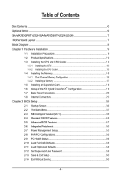
Table of Contents Box Contents...6 Optional Items...6 GA-MA785GPMT-UD2H/GA-MA785GMT-UD2H(US2H 7 Motherboard Layout...7 Block Diagram...8 Chapter 1 Hardware Installation 9 1-1 Installation Precautions 9 1-2 Product Specifications 10 1-3 Installing the CPU and CPU Cooler 13 1-3-1 Installing the CPU 13 1-3-2 Installing the CPU ...
Table of Contents Box Contents...6 Optional Items...6 GA-MA785GPMT-UD2H/GA-MA785GMT-UD2H(US2H 7 Motherboard Layout...7 Block Diagram...8 Chapter 1 Hardware Installation 9 1-1 Installation Precautions 9 1-2 Product Specifications 10 1-3 Installing the CPU and CPU Cooler 13 1-3-1 Installing the CPU 13 1-3-2 Installing the CPU ...
Manual
Page 6
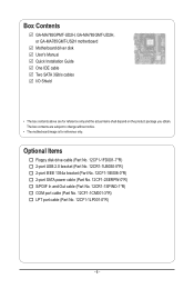
... and Out cable (Part No. 12CR1-1SPINO-1*R) COM port cable (Part No. 12CF1-1CM001-3*R) LPT port cable (Part No. 12CF1-1LP001-0*R) - 6 - Box Contents GA-MA785GPMT-UD2H, GA-MA785GMT-UD2H, or GA-MA785GMT-US2H motherboard Motherboard driver disk User's Manual Quick Installation Guide One IDE cable Two SATA 3Gb/s cables I/O Shield • The box contents above are subject to...
... and Out cable (Part No. 12CR1-1SPINO-1*R) COM port cable (Part No. 12CF1-1CM001-3*R) LPT port cable (Part No. 12CF1-1LP001-0*R) - 6 - Box Contents GA-MA785GPMT-UD2H, GA-MA785GMT-UD2H, or GA-MA785GMT-US2H motherboard Motherboard driver disk User's Manual Quick Installation Guide One IDE cable Two SATA 3Gb/s cables I/O Shield • The box contents above are subject to...
Manual
Page 7
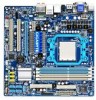
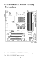
...-UD2H. DDR3_1 DDR3_2 DDR3_3 DDR3_4 M_BIOS IT8718 ATX GA-MA785GPMT-UD2H/GA-MA785GMT-UD2H(US2H) Motherboard Layout DVI VGA KB(Note)_USB ATX_12V_2X4 Socket AM3 B_BIOS CI HDMI USB ESATA 1394 OPTICAL CPU_FAN FDD USB LAN AUDIO F_AUDIO PCIEX1 GA-MA785GPMT-UD2H/ GA-MA785GMT-UD2H/ GA-MA785GMT-US2H AMD 785G SidePort Memoryj NB_FAN RTL8111C PCI1 CD_IN CODEC PCI2 PCIEX16 CLR_CMOS BATTERY...
...-UD2H. DDR3_1 DDR3_2 DDR3_3 DDR3_4 M_BIOS IT8718 ATX GA-MA785GPMT-UD2H/GA-MA785GMT-UD2H(US2H) Motherboard Layout DVI VGA KB(Note)_USB ATX_12V_2X4 Socket AM3 B_BIOS CI HDMI USB ESATA 1394 OPTICAL CPU_FAN FDD USB LAN AUDIO F_AUDIO PCIEX1 GA-MA785GPMT-UD2H/ GA-MA785GMT-UD2H/ GA-MA785GMT-US2H AMD 785G SidePort Memoryj NB_FAN RTL8111C PCI1 CD_IN CODEC PCI2 PCIEX16 CLR_CMOS BATTERY...

Manual
Page 9
...have an ESD wrist strap, keep your hands dry and first touch a metal object to eliminate static electricity. • Prior to installing the motherboard, please have it on top of an antistatic pad or within the computer casing. • Do not place the computer system on an ...to damage to system components as well as physical harm to the user. • If you are connected tightly and securely. • When handling the motherboard, avoid touching any installation steps or have a problem related to the use of the product, please consult a certified computer technician. - 9 - These stickers...
...have an ESD wrist strap, keep your hands dry and first touch a metal object to eliminate static electricity. • Prior to installing the motherboard, please have it on top of an antistatic pad or within the computer casing. • Do not place the computer system on an ...to damage to system components as well as physical harm to the user. • If you are connected tightly and securely. • When handling the motherboard, avoid touching any installation steps or have a problem related to the use of the product, please consult a certified computer technician. - 9 - These stickers...
Manual
Page 12
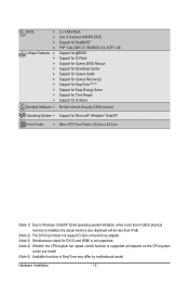
... CPU/system fan speed control function is supported will depend on the CPU/system cooler you install. (Note 5) Available functions in EasyTune may differ by motherboard model.
... CPU/system fan speed control function is supported will depend on the CPU/system cooler you install. (Note 5) Available functions in EasyTune may differ by motherboard model.

Manual
Page 13
... the CPU socket.) • Apply an even and thin layer of thermal grease on the computer if the CPU cooler is not recommended that the motherboard supports the CPU. (Go to GIGABYTE's website for the peripherals.
... the CPU socket.) • Apply an even and thin layer of thermal grease on the computer if the CPU cooler is not recommended that the motherboard supports the CPU. (Go to GIGABYTE's website for the peripherals.

Manual
Page 14
Follow the steps below to correctly install the CPU into the motherboard CPU socket. • Before installing the CPU, make sure to turn off the computer and unplug the power cord from the power outlet to prevent ...
Follow the steps below to correctly install the CPU into the motherboard CPU socket. • Before installing the CPU, make sure to turn off the computer and unplug the power cord from the power outlet to prevent ...

Manual
Page 15
Inadequately removing the CPU cooler may adhere to the CPU fan header (CPU_FAN) on the motherboard. Step 3: Hook the CPU cooler clip to the mounting lug on the retention frame. Hardware Installation On the other side,push straight down on the ... the installed CPU. 1-3-2 Installing the CPU Cooler Follow the steps below to correctly install the CPU cooler on the CPU. (The following procedure uses the GIGABYTE cooler as the picture above shows) to lock into place. (Refer to your CPU cooler installation manual for instructions on installing the cooler.) Step 5: Finally...
Inadequately removing the CPU cooler may adhere to the CPU fan header (CPU_FAN) on the motherboard. Step 3: Hook the CPU cooler clip to the mounting lug on the retention frame. Hardware Installation On the other side,push straight down on the ... the installed CPU. 1-3-2 Installing the CPU Cooler Follow the steps below to correctly install the CPU cooler on the CPU. (The following procedure uses the GIGABYTE cooler as the picture above shows) to lock into place. (Refer to your CPU cooler installation manual for instructions on installing the cooler.) Step 5: Finally...
Manual
Page 16
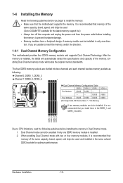
...Sided, "- -"=No Memory) If two memory modules are to insert the memory, switch the direction. 1-4-1 Dual Channel Memory Configuration This motherboard provides four DDR3 memory sockets and supports Dual Channel Technology. When enabling Dual Channel mode with two or four memory modules, it is... recommended that the motherboard supports the memory. A memory module can be used . (Go to GIGABYTE's website for optimum performance. Hardware Installation - 16 - The four DDR3 memory sockets are unable to ...
...Sided, "- -"=No Memory) If two memory modules are to insert the memory, switch the direction. 1-4-1 Dual Channel Memory Configuration This motherboard provides four DDR3 memory sockets and supports Dual Channel Technology. When enabling Dual Channel mode with two or four memory modules, it is... recommended that the motherboard supports the memory. A memory module can be used . (Go to GIGABYTE's website for optimum performance. Hardware Installation - 16 - The four DDR3 memory sockets are unable to ...
Manual
Page 17
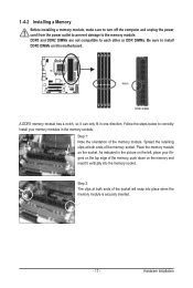
... power cord from the power outlet to prevent damage to correctly install your fingers on the top edge of the memory, push down on this motherboard.
... power cord from the power outlet to prevent damage to correctly install your fingers on the top edge of the memory, push down on this motherboard.
Manual
Page 18
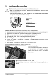
.... Hardware Installation - 18 - 1-5 Installing an Expansion Card Read the following guidelines before installing an expansion card to install an expansion card: • Make sure the motherboard supports the expansion card.
.... Hardware Installation - 18 - 1-5 Installing an Expansion Card Read the following guidelines before installing an expansion card to install an expansion card: • Make sure the motherboard supports the expansion card.
Manual
Page 19
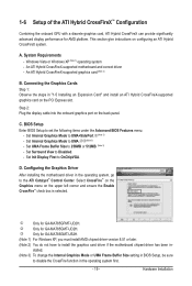
... Size to the ATI Catalyst™ Control Center. Configuring the Graphics Driver After installing the motherboard driver in the operating system first. - 19 - l Only for GA-MA785GMT-UD2H. Hardware Installation This section give instructions on the upper left corner and ensure the Enable...driver if the motherboard chipset driver has been in "1-5 Installing an Expansion Card" and install an ATI Hybrid CrossFireX-supported graphics card on the back panel. Set Internal Graphics Mode to UMA+SidePort.j(Note 3) - D. j Only for AMD platform. k Only for GA-MA785GMT-US2H. (Note ...
... Size to the ATI Catalyst™ Control Center. Configuring the Graphics Driver After installing the motherboard driver in the operating system first. - 19 - l Only for GA-MA785GMT-UD2H. Hardware Installation This section give instructions on the upper left corner and ensure the Enable...driver if the motherboard chipset driver has been in "1-5 Installing an Expansion Card" and install an ATI Hybrid CrossFireX-supported graphics card on the back panel. Set Internal Graphics Mode to UMA+SidePort.j(Note 3) - D. j Only for AMD platform. k Only for GA-MA785GMT-US2H. (Note ...
Manual
Page 21
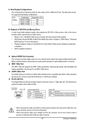
... 3Gb/s standard and is occurring • When removing the cable connected to an external audio system that your device and then remove it from the motherboard. • When removing the cable, pull it side to side to connect an external SATA device or a SATA port multiplier. Connection/ Speed LED Activity LED... LAN port provides Internet connection at up to the recommended system requirements (or better) below shows the supported dual display configurations. Dual Display Configurations: This motherboard provides three ports for an IEEE 1394a device.
... 3Gb/s standard and is occurring • When removing the cable connected to an external audio system that your device and then remove it from the motherboard. • When removing the cable, pull it side to side to connect an external SATA device or a SATA port multiplier. Connection/ Speed LED Activity LED... LAN port provides Internet connection at up to the recommended system requirements (or better) below shows the supported dual display configurations. Dual Display Configurations: This motherboard provides three ports for an IEEE 1394a device.

Manual
Page 23
..., make sure your devices are compliant with the connectors you wish to connect. • Before installing the devices, be sure to the connector on the motherboard. - 23 - Unplug the power cord from the power outlet to prevent damage to the devices. • After installing the device and before connecting external devices...
..., make sure your devices are compliant with the connectors you wish to connect. • Before installing the devices, be sure to the connector on the motherboard. - 23 - Unplug the power cord from the power outlet to prevent damage to the devices. • After installing the device and before connecting external devices...

Manual
Page 24
...not connected, the computer will not start. • To meet expansion requirements, it is turned off and all the components on the motherboard. Do not insert the power supply cables into pins under the protective covers when using a power supply providing a 2x4 12V and ...a 2x12 power connector, remove the protective covers from the 12V power connector and the main power connector on the motherboard. When using a power supply providing a 2x2 12V and a 2x10 power connector. 1 5 4 8 ATX_12V_2X4 ATX_12V_2X4: Pin No. 1/2) ATX_12V_2X4/ATX (...
...not connected, the computer will not start. • To meet expansion requirements, it is turned off and all the components on the motherboard. Do not insert the power supply cables into pins under the protective covers when using a power supply providing a 2x4 12V and ...a 2x12 power connector, remove the protective covers from the 12V power connector and the main power connector on the motherboard. When using a power supply providing a 2x2 12V and a 2x10 power connector. 1 5 4 8 ATX_12V_2X4 ATX_12V_2X4: Pin No. 1/2) ATX_12V_2X4/ATX (...

Manual
Page 25
..., North Bridge and system from overheating. A red power connector wire indicates a positive connection and requires a +12V voltage. Hardware Installation The motherboard supports CPU fan speed control, which requires the use of a CPU fan with color-coded power connector wires. A red power connector wire ... in the correct orientation. Pin No. Do not place a jumper cap on the headers. - 25 - 3/4) CPU_FAN/SYS_FAN (Fan Headers) The motherboard has a 4-pin CPU fan header (CPU_FAN)and a 4-pin system fan header(SYS_FAN). The black connector wire is the ground wire. Each fan ...
..., North Bridge and system from overheating. A red power connector wire indicates a positive connection and requires a +12V voltage. Hardware Installation The motherboard supports CPU fan speed control, which requires the use of a CPU fan with color-coded power connector wires. A red power connector wire ... in the correct orientation. Pin No. Do not place a jumper cap on the headers. - 25 - 3/4) CPU_FAN/SYS_FAN (Fan Headers) The motherboard has a 4-pin CPU fan header (CPU_FAN)and a 4-pin system fan header(SYS_FAN). The black connector wire is the ground wire. Each fan ...
Manual
Page 29
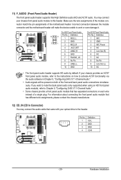
... module to work or even damage it. Definition 1 CD-L 1 2 GND 3 GND 4 CD-R - 29 - Incorrect connection between the module connector and the motherboard header will be present on both of the motherboard header. For HD Front Panel Audio: For AC'97 Front Panel Audio: Pin No. For information about connecting the front panel...
... module to work or even damage it. Definition 1 CD-L 1 2 GND 3 GND 4 CD-R - 29 - Incorrect connection between the module connector and the motherboard header will be present on both of the motherboard header. For HD Front Panel Audio: For AC'97 Front Panel Audio: Pin No. For information about connecting the front panel...


