Manual
Page 3
... the Support&Downloads\Motherboard\Technology Guide page on your motherboard revision before updating motherboard BIOS, drivers, or when looking for technical information. For example, "REV: 1.0" means the revision of the motherboard is the property of this manual may be reproduced, copied, translated, transmitted, or published in this product, GIGABYTE provides the following types of documentations: For quick set-up of the product, read the User's Manual. Copyright...
... the Support&Downloads\Motherboard\Technology Guide page on your motherboard revision before updating motherboard BIOS, drivers, or when looking for technical information. For example, "REV: 1.0" means the revision of the motherboard is the property of this manual may be reproduced, copied, translated, transmitted, or published in this product, GIGABYTE provides the following types of documentations: For quick set-up of the product, read the User's Manual. Copyright...
Manual
Page 4
.../GA-MA785GMT-UD2H(US2H 7 Motherboard Layout...7 Block Diagram...8 Chapter 1 Hardware Installation 9 1-1 Installation Precautions 9 1-2 Product Specifications 10 1-3 Installing the CPU and CPU Cooler 13 1-3-1 Installing the CPU 13 1-3-2 Installing the CPU Cooler 15 1-4 Installing the Memory 16 1-4-1 Dual Channel Memory Configuration 16 1-4-2 Installing a Memory 17 1-5 Installing an Expansion Card 18 1-6 Setup of the ATI Hybrid CrossFireX™ Configuration 19 1-7 Back Panel Connectors 20 1-8 Internal Connectors 23 Chapter 2 BIOS Setup 35 2-1 Startup Screen 36 2-2 The Main Menu...
.../GA-MA785GMT-UD2H(US2H 7 Motherboard Layout...7 Block Diagram...8 Chapter 1 Hardware Installation 9 1-1 Installation Precautions 9 1-2 Product Specifications 10 1-3 Installing the CPU and CPU Cooler 13 1-3-1 Installing the CPU 13 1-3-2 Installing the CPU Cooler 15 1-4 Installing the Memory 16 1-4-1 Dual Channel Memory Configuration 16 1-4-2 Installing a Memory 17 1-5 Installing an Expansion Card 18 1-6 Setup of the ATI Hybrid CrossFireX™ Configuration 19 1-7 Back Panel Connectors 20 1-8 Internal Connectors 23 Chapter 2 BIOS Setup 35 2-1 Startup Screen 36 2-2 The Main Menu...
Manual
Page 5
... with the @BIOS Utility 71 4-3 EasyTune 6...72 4-4 Easy Energy Saver 73 4-5 Q-Share...75 4-6 Time Repair...76 Chapter 5 Appendix...77 5-1 Configuring SATA Hard Drive(s 77 5-1-1 Configuring the Onboard SATA Controller 77 5-1-2 Making a SATA RAID/AHCI Driver Diskette 83 5-1-3 Installing the SATA RAID/AHCI Driver and Operating System 84 5-2 Configuring Audio Input and Output 88 5-2-1 Configuring 2/4/5.1/7.1-Channel Audio 88 5-2-2 Configuring S/PDIF In/Out 90 5-2-3 Enabling the Dolby Home Theater Functionjk 92 5-2-4 Configuring Microphone Recording 93 5-2-5 Using the Sound Recorder 95...
... with the @BIOS Utility 71 4-3 EasyTune 6...72 4-4 Easy Energy Saver 73 4-5 Q-Share...75 4-6 Time Repair...76 Chapter 5 Appendix...77 5-1 Configuring SATA Hard Drive(s 77 5-1-1 Configuring the Onboard SATA Controller 77 5-1-2 Making a SATA RAID/AHCI Driver Diskette 83 5-1-3 Installing the SATA RAID/AHCI Driver and Operating System 84 5-2 Configuring Audio Input and Output 88 5-2-1 Configuring 2/4/5.1/7.1-Channel Audio 88 5-2-2 Configuring S/PDIF In/Out 90 5-2-3 Enabling the Dolby Home Theater Functionjk 92 5-2-4 Configuring Microphone Recording 93 5-2-5 Using the Sound Recorder 95...
Manual
Page 10
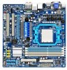
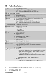
...PCI slots Storage Interface South Bridge: - 1 x IDE connector supporting ATA-133/100/66/33 and up to 2 IDE devices - 5 x SATA 3Gb/s connectors (SATA2_0, SATA2_1, SATA2_2, SATA2_3, SATA2_4) supporting up to 5 SATA 3Gb/s devices - 1 x eSATA 3Gb/s port on the back panel supporting up to 1 SATA 3Gb/s device - 1-2 Product Specifications CPU Support for AM3 processors: AMD Phenom™ II processor/ AMD Athlon™ II processor (Go to GIGABYTE's website for the latest CPU support list.) Hyper Transport Bus 5200 MT/s Chipset Memory...
...PCI slots Storage Interface South Bridge: - 1 x IDE connector supporting ATA-133/100/66/33 and up to 2 IDE devices - 5 x SATA 3Gb/s connectors (SATA2_0, SATA2_1, SATA2_2, SATA2_3, SATA2_4) supporting up to 5 SATA 3Gb/s devices - 1 x eSATA 3Gb/s port on the back panel supporting up to 1 SATA 3Gb/s device - 1-2 Product Specifications CPU Support for AM3 processors: AMD Phenom™ II processor/ AMD Athlon™ II processor (Go to GIGABYTE's website for the latest CPU support list.) Hyper Transport Bus 5200 MT/s Chipset Memory...
Manual
Page 18
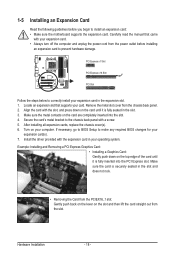
... out from the chassis back panel. 2. Align the card with your expansion card. • Always turn off the computer and unplug the power cord from the power outlet before you begin to make any required BIOS changes for your expansion card(s). 7. If necessary, go to BIOS Setup to install an expansion card: • Make sure the motherboard supports the expansion card. Carefully read the manual that supports your computer...
... out from the chassis back panel. 2. Align the card with your expansion card. • Always turn off the computer and unplug the power cord from the power outlet before you begin to make any required BIOS changes for your expansion card(s). 7. If necessary, go to BIOS Setup to install an expansion card: • Make sure the motherboard supports the expansion card. Carefully read the manual that supports your computer...
Manual
Page 19
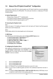
... 3) To change the Internal Graphics Mode or UMA Frame Buffer Size setting in the operating system first. - 19 - Connecting the Graphics Cards Step 1: Observe the steps in - Step 2: Plug the display cable into the onboard graphics port on the PCI Express slot. Set Surround View to set the following items under the Advanced BIOS Features menu: - Windows Vista or Windows XP (Note 1) operating system - An ATI Hybrid CrossFireX-supported graphics card (Note 2) B. BIOS Setup Enter BIOS Setup to Disabled. - D. j Only for GA-MA785GMT-UD2H. A. C. Select...
... 3) To change the Internal Graphics Mode or UMA Frame Buffer Size setting in the operating system first. - 19 - Connecting the Graphics Cards Step 1: Observe the steps in - Step 2: Plug the display cable into the onboard graphics port on the PCI Express slot. Set Surround View to set the following items under the Advanced BIOS Features menu: - Windows Vista or Windows XP (Note 1) operating system - An ATI Hybrid CrossFireX-supported graphics card (Note 2) B. BIOS Setup Enter BIOS Setup to Disabled. - D. j Only for GA-MA785GMT-UD2H. A. C. Select...

Manual
Page 25
... fans are not configuration jumper blocks. Pin No. Overheating may hang. • These fan headers are designed with color-coded power connector wires. Each fan header supplies a +12V power voltage and possesses a foolproof insertion design. A red power connector wire indicates a positive connection and requires a +12V voltage. Definition 1 CPU_FAN 1 GND 2 +12V / Speed Control 3 Sense 4 Speed Control 1 SYS_FAN SYS_FAN: Pin No. 1 2 3 4 Definition GND +12V / Speed Control Sense Reserve 5) NB_FAN (North Bridge Fan Header) Connect the North Bridge fan cable to prevent your CPU...
... fans are not configuration jumper blocks. Pin No. Overheating may hang. • These fan headers are designed with color-coded power connector wires. Each fan header supplies a +12V power voltage and possesses a foolproof insertion design. A red power connector wire indicates a positive connection and requires a +12V voltage. Definition 1 CPU_FAN 1 GND 2 +12V / Speed Control 3 Sense 4 Speed Control 1 SYS_FAN SYS_FAN: Pin No. 1 2 3 4 Definition GND +12V / Speed Control Sense Reserve 5) NB_FAN (North Bridge Fan Header) Connect the North Bridge fan cable to prevent your CPU...
Manual
Page 36
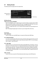
When the motherboard is running at IDE MODE!" Function Keys: : BIOS SETUP Press the key to enter BIOS Setup or to AHCI mode and enable hot plug functionality for one time only. Motherboard Model BIOS Version Award Modular BIOS v6.00PG, An Energy Star Ally Copyright (C) 1984-2009, Award Software, Inc. Press to enable AHCI mode or to enter BIOS Setup first. In Boot Menu, use the up hard drive data using the driver disk, the key can access Boot Menu again to change it to access the Q-Flash utility in Boot Menu. To exit Boot Menu, press . The...
When the motherboard is running at IDE MODE!" Function Keys: : BIOS SETUP Press the key to enter BIOS Setup or to AHCI mode and enable hot plug functionality for one time only. Motherboard Model BIOS Version Award Modular BIOS v6.00PG, An Energy Star Ally Copyright (C) 1984-2009, Award Software, Inc. Press to enable AHCI mode or to enter BIOS Setup first. In Boot Menu, use the up hard drive data using the driver disk, the key can access Boot Menu again to change it to access the Q-Flash utility in Boot Menu. To exit Boot Menu, press . The...

Manual
Page 38
... CPU, memory, etc. Standard CMOS Features Use this menu to configure the system time and date, hard drive types, floppy disk drive types, and the type of errors that stop the system boot, etc. Advanced BIOS Features Use this menu to configure the device boot order, advanced features available on the CPU, and the primary display adapter. Integrated Peripherals Use this menu to configure all peripheral devices, such as IDE, SATA, USB, integrated audio, and integrated LAN, etc. Power Management Setup Use...
... CPU, memory, etc. Standard CMOS Features Use this menu to configure the system time and date, hard drive types, floppy disk drive types, and the type of errors that stop the system boot, etc. Advanced BIOS Features Use this menu to configure the device boot order, advanced features available on the CPU, and the primary display adapter. Integrated Peripherals Use this menu to configure all peripheral devices, such as IDE, SATA, USB, integrated audio, and integrated LAN, etc. Power Management Setup Use...

Manual
Page 41
...manually set in accordance with the CPU specifications. This item is configurable only if the VGA Core Clock control option is highly recommended that the CPU frequency be set the VGA Core clock. Auto lets BIOS automatically set the memory clock. Manual allows the CPU Frequency (MHz) item below to be configurable. Important It is enabled. Auto BIOS will automatically adjust the HT Link Frequency. (Default) x1~x10 Sets HT Link Frequency to Manual. BIOS Setup CPU Host Clock Control Enables or disables the control of VGA Core clock. (Default: Disabled) VGA Core Clock...
...manually set in accordance with the CPU specifications. This item is configurable only if the VGA Core Clock control option is highly recommended that the CPU frequency be set the VGA Core clock. Auto lets BIOS automatically set the memory clock. Manual allows the CPU Frequency (MHz) item below to be configurable. Important It is enabled. Auto BIOS will automatically adjust the HT Link Frequency. (Default) x1~x10 Sets HT Link Frequency to Manual. BIOS Setup CPU Host Clock Control Enables or disables the control of VGA Core clock. (Default: Disabled) VGA Core Clock...
Manual
Page 47
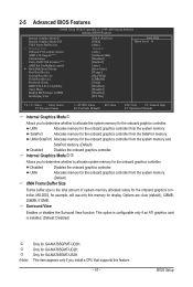
... Mode j Internal Graphics Mode kl UMA Frame Buffer Size x Surround View Onboard VGA output connect AMD C1E Support (Note) Virtualization Patch AMD TLB Erratum (Note) AMD K8 Cool&Quiet control } Hard Disk Boot Priority First Boot Device Second Boot Device Third Boot Device Password Check HDD S.M.A.R.T. Capability Away Mode Backup BIOS Image to HDD Init Display First [UMA+SidePort] [UMA] [Auto] Disabled [Auto] [Software SMI] [Disabled] [Enabled] [Auto] [Press Enter] [Floppy] [Hard Disk] [CDROM] [Setup] [Disabled] [Disabled] [Disabled] [PCI Slot...
... Mode j Internal Graphics Mode kl UMA Frame Buffer Size x Surround View Onboard VGA output connect AMD C1E Support (Note) Virtualization Patch AMD TLB Erratum (Note) AMD K8 Cool&Quiet control } Hard Disk Boot Priority First Boot Device Second Boot Device Third Boot Device Password Check HDD S.M.A.R.T. Capability Away Mode Backup BIOS Image to HDD Init Display First [UMA+SidePort] [UMA] [Auto] Disabled [Auto] [Software SMI] [Disabled] [Enabled] [Auto] [Press Enter] [Floppy] [Hard Disk] [CDROM] [Setup] [Disabled] [Disabled] [Disabled] [PCI Slot...

Manual
Page 48
... on the list. Options are: Floppy, LS120, Hard Disk, CDROM, ZIP, USB-FDD, USB-ZIP, USB-CDROM, USB-HDD, Legacy LAN, Disabled. Password Check Specifies whether a password is connected, D-SUB/DVI-D or D-SUB/HDMI. (Default) D-SUB/DVI Sets the D-SUB/DVI-D as the graphics display. First/Second/Third Boot Device Specifies the boot order from the installed hard drives. Hard Disk Boot Priority Specifies the sequence of loading the operating system from the available devices. BIOS Setup - 48 - When enabled, the CPU core frequency and voltage will be reduced...
... on the list. Options are: Floppy, LS120, Hard Disk, CDROM, ZIP, USB-FDD, USB-ZIP, USB-CDROM, USB-HDD, Legacy LAN, Disabled. Password Check Specifies whether a password is connected, D-SUB/DVI-D or D-SUB/HDMI. (Default) D-SUB/DVI Sets the D-SUB/DVI-D as the graphics display. First/Second/Third Boot Device Specifies the boot order from the installed hard drives. Hard Disk Boot Priority Specifies the sequence of loading the operating system from the available devices. BIOS Setup - 48 - When enabled, the CPU core frequency and voltage will be reduced...

Manual
Page 50
... CMOS Setup Utility-Copyright (C) 1984-2009 Award Software Integrated Peripherals OnChip IDE Channel OnChip SATA Controller OnChip SATA Type x OnChip SATA Port4/5 Type Onboard LAN Function Onboard LAN Boot ROM } SMART LAN Onboard Audio Function Onboard 1394 Function OnChip USB Controller USB EHCI Controller USB Keyboard Support USB Mouse Support Legacy USB storage detect Onboard Serial Port 1 Onboard Parallel Port Parallel Port Mode x ECP Mode Use DMA [Enabled] [Enabled] [Native IDE] IDE [Enabled] [Disabled] [Press Enter] [Enabled] [Enabled...
... CMOS Setup Utility-Copyright (C) 1984-2009 Award Software Integrated Peripherals OnChip IDE Channel OnChip SATA Controller OnChip SATA Type x OnChip SATA Port4/5 Type Onboard LAN Function Onboard LAN Boot ROM } SMART LAN Onboard Audio Function Onboard 1394 Function OnChip USB Controller USB EHCI Controller USB Keyboard Support USB Mouse Support Legacy USB storage detect Onboard Serial Port 1 Onboard Parallel Port Parallel Port Mode x ECP Mode Use DMA [Enabled] [Enabled] [Native IDE] IDE [Enabled] [Disabled] [Press Enter] [Enabled] [Enabled...

Manual
Page 52
... mode. Options are : 378/IRQ7 (default), 278/IRQ5, 3BC/IRQ7, Disabled. Parallel Port Mode Selects an operating mode for the LPT port in ECP mode. BIOS Setup - 52 - USB EHCI Controller Enables or disables the integrated USB 2.0 controller. (Default: Enabled) USB Keyboard Support Allows USB keyboard to be used in MS-DOS. (Default: Enabled) USB Mouse Support Allows USB mouse to be used in MS-DOS. (Default: Disabled) Legacy USB storage detect Determines whether to detect USB storage devices, including USB flash drives and USB hard drives during the POST. (Default: Enabled) Onboard Serial...
... mode. Options are : 378/IRQ7 (default), 278/IRQ5, 3BC/IRQ7, Disabled. Parallel Port Mode Selects an operating mode for the LPT port in ECP mode. BIOS Setup - 52 - USB EHCI Controller Enables or disables the integrated USB 2.0 controller. (Default: Enabled) USB Keyboard Support Allows USB keyboard to be used in MS-DOS. (Default: Enabled) USB Mouse Support Allows USB mouse to be used in MS-DOS. (Default: Disabled) Legacy USB storage detect Determines whether to detect USB storage devices, including USB flash drives and USB hard drives during the POST. (Default: Enabled) Onboard Serial...

Manual
Page 53
.... BIOS Setup Soft-Off by Power button Configures the way to turn off instantly. (Default) Delay 4 Sec. 2-7 Power Management Setup CMOS Setup Utility-Copyright (C) 1984-2009 Award Software Power Management Setup ACPI Suspend Type Soft-Off by Power button USB Wake Up from a modem that supports wake-up device or event, the system resumes to its working state exactly where it was left off. In S1 sleep state, the system appears suspended and stays in a low power mode. If...
.... BIOS Setup Soft-Off by Power button Configures the way to turn off instantly. (Default) Delay 4 Sec. 2-7 Power Management Setup CMOS Setup Utility-Copyright (C) 1984-2009 Award Software Power Management Setup ACPI Suspend Type Soft-Off by Power button USB Wake Up from a modem that supports wake-up device or event, the system resumes to its working state exactly where it was left off. In S1 sleep state, the system appears suspended and stays in a low power mode. If...

Manual
Page 77
..., it is set to available SATA port on the motherboard. Install SATA hard drive(s) in your computer Attach one hard drive. • An empty formatted floppy disk. • Windows Vista/XP setup disk. • Motherboard driver disk. 5-1-1 Configuring the Onboard SATA Controller A. Install the SATA RAID/AHCI driver (Note 2) and operating system. Before you begin Please prepare: • At least two SATA hard drives (to create RAID, you use two hard drives with identical model and capacity). Installing SATA hard drive(s) in your power supply to the hard drive. (Note 1) Skip...
..., it is set to available SATA port on the motherboard. Install SATA hard drive(s) in your computer Attach one hard drive. • An empty formatted floppy disk. • Windows Vista/XP setup disk. • Motherboard driver disk. 5-1-1 Configuring the Onboard SATA Controller A. Install the SATA RAID/AHCI driver (Note 2) and operating system. Before you begin Please prepare: • At least two SATA hard drives (to create RAID, you use two hard drives with identical model and capacity). Installing SATA hard drive(s) in your power supply to the hard drive. (Note 1) Skip...
Manual
Page 83
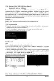
... the motherboard driver disk to copy the Windows 64-bit driver. - 83 - 5-1-2 Making a SATA RAID/AHCI Driver Diskette (Required for AHCI and RAID Mode) To successfully install operating system onto SATA hard drive(s) that is D:\). 3: At the A:\> prompt, type the following command. For installing Windows Vista, you need to a USB flash drive. Your system will open similar to that has CD-ROM support and a blank formatted floppy disk. For example, from the motherboard driver disk to install the SATA controller driver during the Windows setup process...
... the motherboard driver disk to copy the Windows 64-bit driver. - 83 - 5-1-2 Making a SATA RAID/AHCI Driver Diskette (Required for AHCI and RAID Mode) To successfully install operating system onto SATA hard drive(s) that is D:\). 3: At the A:\> prompt, type the following command. For installing Windows Vista, you need to a USB flash drive. Your system will open similar to that has CD-ROM support and a blank formatted floppy disk. For example, from the motherboard driver disk to install the SATA controller driver during the Windows setup process...
Manual
Page 84
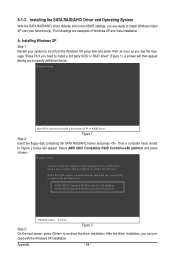
... previous screen. ceed with Windows, using a device support disk provided by an adapter manufacturer. The followings are ready to install Windows Vista/ XP onto your system to boot from the following list, or press ESC to return to install a 3rd party SCSI or RAID driver" (Figure 1). A. 5-1-3 Installing the SATA RAID/AHCI Driver and Operating System With the SATA RAID/AHCI driver diskette and correct BIOS settings, you are examples of Windows XP and Vista installation. Windows Setup Press...
... previous screen. ceed with Windows, using a device support disk provided by an adapter manufacturer. The followings are ready to install Windows Vista/ XP onto your system to boot from the following list, or press ESC to return to install a 3rd party SCSI or RAID driver" (Figure 1). A. 5-1-3 Installing the SATA RAID/AHCI Driver and Operating System With the SATA RAID/AHCI driver diskette and correct BIOS settings, you are examples of Windows XP and Vista installation. Windows Setup Press...
Manual
Page 88
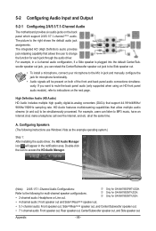
woofer speaker out jack, you want to mute the back panel audio (only supported when using an HD front panel audio module), refer to the following instructions use Windows Vista as the example operating system.) Step 1: After installing the audio driver, the HD Audio Manager icon will be simultaneously processed. Appendix - 88 - all at the same time. j Only for GA-MA785GMT-UD2H. k Only for GA-MA785GPMT-UD2H. A. Double...
woofer speaker out jack, you want to mute the back panel audio (only supported when using an HD front panel audio module), refer to the following instructions use Windows Vista as the example operating system.) Step 1: After installing the audio driver, the HD Audio Manager icon will be simultaneously processed. Appendix - 88 - all at the same time. j Only for GA-MA785GMT-UD2H. k Only for GA-MA785GPMT-UD2H. A. Double...
Manual
Page 96
... Device Manager or Sound, video, and game controllers. You can temporarily remove the battery from Microsoft's website. A: Make sure your motherboard, please go to show the advanced options. Step 2: Check if Audio Device on GIGABYTE's website. A: The following Award BIOS beep code descriptions may help you identify possible computer problems. (For reference only.) 1 short: System boots successfully 1 long, 3 short: Keyboard error 2 short: CMOS setting error 1 long, 9 short: BIOS ROM error 1 long, 1 short: Memory or motherboard error Continuous long beeps: Graphics card...
... Device Manager or Sound, video, and game controllers. You can temporarily remove the battery from Microsoft's website. A: Make sure your motherboard, please go to show the advanced options. Step 2: Check if Audio Device on GIGABYTE's website. A: The following Award BIOS beep code descriptions may help you identify possible computer problems. (For reference only.) 1 short: System boots successfully 1 long, 3 short: Keyboard error 2 short: CMOS setting error 1 long, 9 short: BIOS ROM error 1 long, 1 short: Memory or motherboard error Continuous long beeps: Graphics card...


