Manual
Page 3
... on/from the Support&Downloads\Motherboard\Technology Guide page on our website. For instructions on your motherboard revision before updating motherboard BIOS, drivers, or when looking for technical information. Check your motherboard looks like this manual is protected by any form or ...by copyright laws and is 1.0. The trademarks mentioned in the use GIGABYTE's unique features, read the User's Manual. Disclaimer Information in any means without prior notice. Documentation Classifications In order to assist in...
... on/from the Support&Downloads\Motherboard\Technology Guide page on our website. For instructions on your motherboard revision before updating motherboard BIOS, drivers, or when looking for technical information. Check your motherboard looks like this manual is protected by any form or ...by copyright laws and is 1.0. The trademarks mentioned in the use GIGABYTE's unique features, read the User's Manual. Disclaimer Information in any means without prior notice. Documentation Classifications In order to assist in...
Manual
Page 4
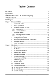
Table of Contents Box Contents...6 Optional Items...6 GA-MA785GPMT-UD2H/GA-MA785GMT-UD2H(US2H 7 Motherboard Layout...7 Block Diagram...8 Chapter 1 Hardware Installation 9 1-1 Installation Precautions 9 1-2 Product Specifications 10 1-3 Installing the CPU and CPU...8482; Configuration 19 1-7 Back Panel Connectors 20 1-8 Internal Connectors 23 Chapter 2 BIOS Setup 35 2-1 Startup Screen 36 2-2 The Main Menu 37 2-3 MB Intelligent Tweaker(M.I.T 39 2-4 Standard CMOS Features 45 2-5 Advanced BIOS Features 47 2-6 Integrated Peripherals 50 2-7 Power Management Setup 53 2-8 PnP/PCI ...
Table of Contents Box Contents...6 Optional Items...6 GA-MA785GPMT-UD2H/GA-MA785GMT-UD2H(US2H 7 Motherboard Layout...7 Block Diagram...8 Chapter 1 Hardware Installation 9 1-1 Installation Precautions 9 1-2 Product Specifications 10 1-3 Installing the CPU and CPU...8482; Configuration 19 1-7 Back Panel Connectors 20 1-8 Internal Connectors 23 Chapter 2 BIOS Setup 35 2-1 Startup Screen 36 2-2 The Main Menu 37 2-3 MB Intelligent Tweaker(M.I.T 39 2-4 Standard CMOS Features 45 2-5 Advanced BIOS Features 47 2-6 Integrated Peripherals 50 2-7 Power Management Setup 53 2-8 PnP/PCI ...
Manual
Page 5
...Only for GA-MA785GPMT-UD2H. Chapter 3 Drivers Installation 61 3-1 Installing Chipset Drivers 61 3-2 Application Software 62 3-3 Technical Manuals 62 3-4 Contact...63 3-5 System...63 3-6 Download Center 64 Chapter 4 Unique Features 65 4-1 Xpress Recovery2 65 4-2 BIOS Update Utilities 68 4-2-1 Updating the BIOS with the Q-Flash Utility 68 4-2-2 Updating the BIOS with the @BIOS Utility 71... 5-2-5 Using the Sound Recorder 95 5-3 Troubleshooting 96 5-3-1 Frequently Asked Questions 96 5-3-2 Troubleshooting Procedure 97 5-4 Regulatory Statements 99 j Only for GA-MA785GMT-UD2H. - 5 -
...Only for GA-MA785GPMT-UD2H. Chapter 3 Drivers Installation 61 3-1 Installing Chipset Drivers 61 3-2 Application Software 62 3-3 Technical Manuals 62 3-4 Contact...63 3-5 System...63 3-6 Download Center 64 Chapter 4 Unique Features 65 4-1 Xpress Recovery2 65 4-2 BIOS Update Utilities 68 4-2-1 Updating the BIOS with the Q-Flash Utility 68 4-2-2 Updating the BIOS with the @BIOS Utility 71... 5-2-5 Using the Sound Recorder 95 5-3 Troubleshooting 96 5-3-1 Frequently Asked Questions 96 5-3-2 Troubleshooting Procedure 97 5-4 Regulatory Statements 99 j Only for GA-MA785GMT-UD2H. - 5 -

Manual
Page 8
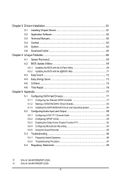
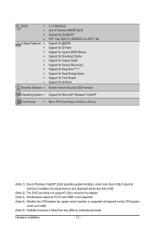
... Express x16 Dual Channel Memory Hyper Transport 3.0 PCI Express x16 PCI Express Bus x1 PCIe CLK (100 MHz) 1 PCI Express x1 RTL8111C RJ45 LAN Dual BIOS PCI Bus TSB43AB23 2 IEEE 1394a AMD 785G GFX CLK (100 MHz) D-Sub DVI-D or HDMI (Note) DDR3 SidePort Memoryj 12 USB Ports AMD SB710 ATA... Speaker Out Center/Subwoofer Speaker Out Side Speaker Out MIC Line Out Line In S/PDIF In S/ PDIF Out 2 PCI PCI CLK (33 MHz) j Only for GA-MA785GPMT-UD2H. (Note) Simultaneous output for DVI-D and HDMI is not supported. - 8 -
... Express x16 Dual Channel Memory Hyper Transport 3.0 PCI Express x16 PCI Express Bus x1 PCIe CLK (100 MHz) 1 PCI Express x1 RTL8111C RJ45 LAN Dual BIOS PCI Bus TSB43AB23 2 IEEE 1394a AMD 785G GFX CLK (100 MHz) D-Sub DVI-D or HDMI (Note) DDR3 SidePort Memoryj 12 USB Ports AMD SB710 ATA... Speaker Out Center/Subwoofer Speaker Out Side Speaker Out MIC Line Out Line In S/PDIF In S/ PDIF Out 2 PCI PCI CLK (33 MHz) j Only for GA-MA785GPMT-UD2H. (Note) Simultaneous output for DVI-D and HDMI is not supported. - 8 -
Manual
Page 12
... w w w w w w w w w w Bundled Software w 2 x 8 Mbit flash Use of licensed AWARD BIOS Support for DualBIOS™ PnP 1.0a, DMI 2.0, SM BIOS 2.4, ACPI 1.0b Support for @BIOS Support for Q-Flash Support for Xpress BIOS Rescue Support for Download Center Support for Xpress Install Support for Xpress Recovery2 Support for EasyTune (Note 5) Support for Easy Energy Saver Support for...
... w w w w w w w w w w Bundled Software w 2 x 8 Mbit flash Use of licensed AWARD BIOS Support for DualBIOS™ PnP 1.0a, DMI 2.0, SM BIOS 2.4, ACPI 1.0b Support for @BIOS Support for Q-Flash Support for Xpress BIOS Rescue Support for Download Center Support for Xpress Install Support for Xpress Recovery2 Support for EasyTune (Note 5) Support for Easy Energy Saver Support for...
Manual
Page 16
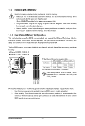
... are to be installed, it is recommended that memory of the same capacity, brand, speed, and chips be used . (Go to GIGABYTE's website for optimum performance. 1-4 Installing the Memory Read the following guidelines before you begin to install the memory: • Make sure that...8226; Memory modules have a foolproof design. After the memory is recommended that the motherboard supports the memory. It is installed, the BIOS will double the original memory bandwidth. Enabling Dual Channel memory mode will automatically detect the specifications and capacity of the memory. Dual ...
... are to be installed, it is recommended that memory of the same capacity, brand, speed, and chips be used . (Go to GIGABYTE's website for optimum performance. 1-4 Installing the Memory Read the following guidelines before you begin to install the memory: • Make sure that...8226; Memory modules have a foolproof design. After the memory is recommended that the motherboard supports the memory. It is installed, the BIOS will double the original memory bandwidth. Enabling Dual Channel memory mode will automatically detect the specifications and capacity of the memory. Dual ...
Manual
Page 18
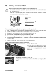
... Express x1 Slot PCI Express x16 Slot PCI Slot Follow the steps below to correctly install your expansion card(s). 7. If necessary, go to BIOS Setup to make any required BIOS changes for your expansion card in the slot and does not rock. • Removing the Card from the slot. Install the driver...
... Express x1 Slot PCI Express x16 Slot PCI Slot Follow the steps below to correctly install your expansion card(s). 7. If necessary, go to BIOS Setup to make any required BIOS changes for your expansion card in the slot and does not rock. • Removing the Card from the slot. Install the driver...
Manual
Page 19
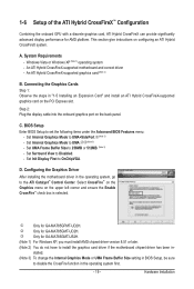
...Internal Graphics Mode to UMA+SidePort.j(Note 3) - Set UMA Frame Buffer Size to set the following items under the Advanced BIOS Features menu: - D. k Only for GA-MA785GMT-US2H. (Note 1) For Windows XP, you must install AMD chipset driver version 8.51 or later. (Note 2) You do... the steps in the operating system, go to OnChipVGA. l Only for GA-MA785GMT-UD2H. System Requirements - BIOS Setup Enter BIOS Setup to 256MB or 512MB. (Note 3) - Set Surround View to disable the CrossFire function in BIOS Setup, be sure to Disabled. - j Only for AMD platform. Hardware...
...Internal Graphics Mode to UMA+SidePort.j(Note 3) - Set UMA Frame Buffer Size to set the following items under the Advanced BIOS Features menu: - D. k Only for GA-MA785GMT-US2H. (Note 1) For Windows XP, you must install AMD chipset driver version 8.51 or later. (Note 2) You do... the steps in the operating system, go to OnChipVGA. l Only for GA-MA785GMT-UD2H. System Requirements - BIOS Setup Enter BIOS Setup to 256MB or 512MB. (Note 3) - Set Surround View to disable the CrossFire function in BIOS Setup, be sure to Disabled. - j Only for AMD platform. Hardware...
Manual
Page 21
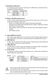
... Do not rock it straight out from the motherboard. • When removing the cable, pull it side to side to Chapter 2, "BIOS Setup," "Advanced BIOS Features," for an IEEE 1394a device. Before using this port for more information) • Playback software: CyberLink PowerDVD 8.0 or later ... Description Blinking Data transmission or receiving is occurring Off No data transmission or receiving is compatible with dual channel mode enabled • BIOS Setup: At least 256 MB of UMA Frame Buffer Size (refer to prevent an electrical short inside the cable connector. - 21...
... Do not rock it straight out from the motherboard. • When removing the cable, pull it side to side to Chapter 2, "BIOS Setup," "Advanced BIOS Features," for an IEEE 1394a device. Before using this port for more information) • Playback software: CyberLink PowerDVD 8.0 or later ... Description Blinking Data transmission or receiving is occurring Off No data transmission or receiving is compatible with dual channel mode enabled • BIOS Setup: At least 256 MB of UMA Frame Buffer Size (refer to prevent an electrical short inside the cable connector. - 21...

Manual
Page 28
...on the chassis front panel. The system reports system startup status by chassis. When connecting your system using the power switch (refer to Chapter 2, "BIOS Setup," "Power Management Setup," for information about beep codes. • HD (Hard Drive Activity LED, Blue) Connects to this header according to ...Header) Connect the power switch, reset switch, speaker and system status indicator on the chassis front panel. The LED S0 On is detected, the BIOS may configure the way to turn off (S5). • PW (Power Switch, Red): Connects to the speaker on when the system is ...
...on the chassis front panel. The system reports system startup status by chassis. When connecting your system using the power switch (refer to Chapter 2, "BIOS Setup," "Power Management Setup," for information about beep codes. • HD (Hard Drive Activity LED, Blue) Connects to this header according to ...Header) Connect the power switch, reset switch, speaker and system status indicator on the chassis front panel. The LED S0 On is detected, the BIOS may configure the way to turn off (S5). • PW (Power Switch, Red): Connects to the speaker on when the system is ...

Manual
Page 33
...computer is replaced with an incorrect model. • Contact the place of purchase or local dealer if you are not able to Chapter 2, "BIOS Setup," for one . self or uncertain about the battery model. • When installing the battery, note the orientation of the positive side ...with an equivalent one minute. (Or use a metal object like a screwdriver to touch the two pins for 5 seconds.) 3. date information and BIOS configurations) and reset the CMOS values to clear the CMOS values (e.g. Turn off your - Hardware Installation You may be accurate or may clear the ...
...computer is replaced with an incorrect model. • Contact the place of purchase or local dealer if you are not able to Chapter 2, "BIOS Setup," for one . self or uncertain about the battery model. • When installing the battery, note the orientation of the positive side ...with an equivalent one minute. (Or use a metal object like a screwdriver to touch the two pins for 5 seconds.) 3. date information and BIOS configurations) and reset the CMOS values to clear the CMOS values (e.g. Turn off your - Hardware Installation You may be accurate or may clear the ...

Manual
Page 35
... you need to) to clear the CMOS values.) - 35 - To upgrade the BIOS, use either the GIGABYTE Q-Flash or @BIOS utility. • Q-Flash allows the user to quickly and easily upgrade or back up BIOS without entering the operating system. • @BIOS is recommended that allows the user to modify basic system configuration settings or...
... you need to) to clear the CMOS values.) - 35 - To upgrade the BIOS, use either the GIGABYTE Q-Flash or @BIOS utility. • Q-Flash allows the user to quickly and easily upgrade or back up BIOS without entering the operating system. • @BIOS is recommended that allows the user to modify basic system configuration settings or...
Manual
Page 36
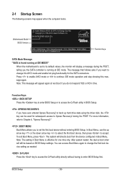
...continue IDE mode operation and stop showing this message again. You can be based on BIOS Setup settings. 2-1 Startup Screen The following screens may appear when the computer boots. GA-MA785GPMT-UD2H E3c . . . . : BIOS Setup : XpressRecovery2 : Boot Menu : Qflash 06/05/2009-RS785-SB710-7A66BG03C-00 ... used for one time only. After system restart, the device boot order will display a message during the POST. Motherboard Model BIOS Version Award Modular BIOS v6.00PG, An Energy Star Ally Copyright (C) 1984-2009, Award Software, Inc. Press to enable AHCI mode or to Xpress...
...continue IDE mode operation and stop showing this message again. You can be based on BIOS Setup settings. 2-1 Startup Screen The following screens may appear when the computer boots. GA-MA785GPMT-UD2H E3c . . . . : BIOS Setup : XpressRecovery2 : Boot Menu : Qflash 06/05/2009-RS785-SB710-7A66BG03C-00 ... used for one time only. After system restart, the device boot order will display a message during the POST. Motherboard Model BIOS Version Award Modular BIOS v6.00PG, An Energy Star Ally Copyright (C) 1984-2009, Award Software, Inc. Press to enable AHCI mode or to Xpress...
Manual
Page 37
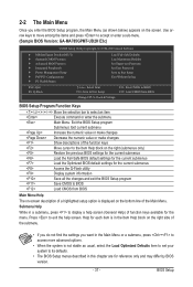
...described in this chapter are for reference only and may differ by BIOS version. - 37 - Use arrow keys to move among the items and press to accept or enter a sub-menu. (Sample BIOS Version: GA-MA785GPMT-UD2H E3c) CMOS Setup Utility-Copyright (C) 1984-2009 Award ...Software MB Intelligent Tweaker(M.I.T.) Standard CMOS Features Advanced BIOS Features Integrated Peripherals Power Management Setup ...
...described in this chapter are for reference only and may differ by BIOS version. - 37 - Use arrow keys to move among the items and press to accept or enter a sub-menu. (Sample BIOS Version: GA-MA785GPMT-UD2H E3c) CMOS Setup Utility-Copyright (C) 1984-2009 Award ...Software MB Intelligent Tweaker(M.I.T.) Standard CMOS Features Advanced BIOS Features Integrated Peripherals Power Management Setup ...

Manual
Page 38
...time and date, hard drive types, floppy disk drive types, and the type of errors that stop the system boot, etc. Advanced BIOS Features Use this menu to configure the device boot order, advanced features available on the CPU, and the primary display adapter. Integrated ...devices, such as IDE, SATA, USB, integrated audio, and integrated LAN, etc. Power Management Setup Use this menu to the system and BIOS Setup. It allows you to restrict access to see information about autodetected system/CPU temperature, system voltage and fan speed, etc. Load Fail...
...time and date, hard drive types, floppy disk drive types, and the type of errors that stop the system boot, etc. Advanced BIOS Features Use this menu to configure the device boot order, advanced features available on the CPU, and the primary display adapter. Integrated ...devices, such as IDE, SATA, USB, integrated audio, and integrated LAN, etc. Power Management Setup Use this menu to the system and BIOS Setup. It allows you to restrict access to see information about autodetected system/CPU temperature, system voltage and fan speed, etc. Load Fail...
Manual
Page 39
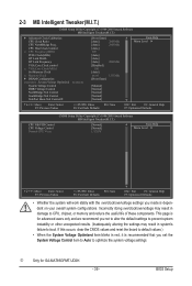
...not to alter the default settings to prevent system instability or other unexpected results. (Inadequately altering the settings may result in red, it is for GA-MA785GPMT-UD2H. - 39 - If this occurs, clear the CMOS values and reset the board to boot. This page is recommended that you ...set the System Voltage Control item to Auto to CPU, chipset, or memory and reduce the useful life of these components. BIOS Setup CPU Host Clock Control x CPU Frequency(MHz) PCIE Clock(MHz) HT Link Width HT Link Frequency VGA Core Clock control x VGA Core...
...not to alter the default settings to prevent system instability or other unexpected results. (Inadequately altering the settings may result in red, it is for GA-MA785GPMT-UD2H. - 39 - If this occurs, clear the CMOS values and reset the board to boot. This page is recommended that you ...set the System Voltage Control item to Auto to CPU, chipset, or memory and reduce the useful life of these components. BIOS Setup CPU Host Clock Control x CPU Frequency(MHz) PCIE Clock(MHz) HT Link Width HT Link Frequency VGA Core Clock control x VGA Core...

Manual
Page 40
...Default) Hybrid Uses the specific AMD EC firmware version. Per Core Individually configures Advanced Clock Calibration for the settings to take effect. BIOS Setup - 40 - Advanced Clock Calibration Allows you to select the EC firmware version when Advanced Clock Calibration is enabled. Value (...Calibration for all CPU cores. Options are : -12%~+12%. Options are : -12%~+12%. Disabled Disables this function. (Default) Auto Lets the BIOS to configure the settings to All Cores. Value (Core 0), Value (Core 1), Value (Core 2), Value (Core 3) This option is configurable only ...
...Default) Hybrid Uses the specific AMD EC firmware version. Per Core Individually configures Advanced Clock Calibration for the settings to take effect. BIOS Setup - 40 - Advanced Clock Calibration Allows you to select the EC firmware version when Advanced Clock Calibration is enabled. Value (...Calibration for all CPU cores. Options are : -12%~+12%. Options are : -12%~+12%. Disabled Disables this function. (Default) Auto Lets the BIOS to configure the settings to All Cores. Value (Core 0), Value (Core 1), Value (Core 2), Value (Core 3) This option is configurable only ...

Manual
Page 41
... CPU being used . This item is configurable only if the VGA Core Clock control option is from 200 MHz to default values. Auto lets BIOS automatically set the width for automated system reboot, or clear the CMOS values to reset the board to 2000 MHz. Auto (default) allows the... (MHz) item below to be set in accordance with the CPU specifications. CPU Frequency(MHz) Allows you to x1~x10 (200 MHz~2.0 GHz). Auto BIOS will automatically adjust the HT Link Frequency. (Default) x1~x10 Sets HT Link Frequency to manually set the memory clock as required. The adjustable range...
... CPU being used . This item is configurable only if the VGA Core Clock control option is from 200 MHz to default values. Auto lets BIOS automatically set the width for automated system reboot, or clear the CMOS values to reset the board to 2000 MHz. Auto (default) allows the... (MHz) item below to be set in accordance with the CPU specifications. CPU Frequency(MHz) Allows you to x1~x10 (200 MHz~2.0 GHz). Auto BIOS will automatically adjust the HT Link Frequency. (Default) x1~x10 Sets HT Link Frequency to manually set the memory clock as required. The adjustable range...
Manual
Page 42
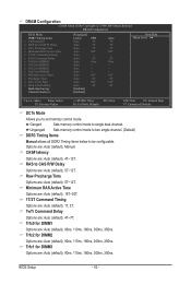
... Options are : Auto (default), Manual. Trfc1 for DIMM3 Options are : Auto (default), 4T~12T. CAS# latency Options are : Auto (default), 90ns, 110ns, 160ns, 300ns, 350ns. BIOS Setup - 42 - TwTr Command Delay Options are: Auto (default), 4T~7T. DRAM Configuration CMOS Setup Utility-Copyright (C) 1984-2009 Award Software DRAM Configuration DCTs Mode...
... Options are : Auto (default), Manual. Trfc1 for DIMM3 Options are : Auto (default), 4T~12T. CAS# latency Options are : Auto (default), 90ns, 110ns, 160ns, 300ns, 350ns. BIOS Setup - 42 - TwTr Command Delay Options are: Auto (default), 4T~7T. DRAM Configuration CMOS Setup Utility-Copyright (C) 1984-2009 Award Software DRAM Configuration DCTs Mode...
Manual
Page 43
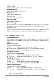
...memory to increase memory performance and stability. (Default: Enabled) ******** System Voltage Optimized ******** System Voltage Control Determines whether to 0.3V at 0.05V increment. Auto lets the BIOS automatically set the SidePort memory voltage. Precharge Time Options are : Auto (default), 90ns, 110ns, 160ns, 300ns, 350ns. Normal Supplies the memory voltage as required. ...you to set the system voltages as required. (Default) +0.050V ~ +0.750V Increases memory voltage by 0.1V to manually set the South Bridge voltage. Trfc3 for GA-MA785GPMT-UD2H. - 43 - BIOS Setup
...memory to increase memory performance and stability. (Default: Enabled) ******** System Voltage Optimized ******** System Voltage Control Determines whether to 0.3V at 0.05V increment. Auto lets the BIOS automatically set the SidePort memory voltage. Precharge Time Options are : Auto (default), 90ns, 110ns, 160ns, 300ns, 350ns. Normal Supplies the memory voltage as required. ...you to set the system voltages as required. (Default) +0.050V ~ +0.750V Increases memory voltage by 0.1V to manually set the South Bridge voltage. Trfc3 for GA-MA785GPMT-UD2H. - 43 - BIOS Setup


