Manual
Page 3
.../from the Support&Downloads\Motherboard\Technology Guide page on your motherboard revision before updating motherboard BIOS, drivers, or when looking for technical information. All rights reserved. Check your motherboard looks like this manual may be reproduced, copied, translated, transmitted, or published in the use GIGABYTE's unique features, read the User's Manual. Copyright © 2009 GIGA-BYTE TECHNOLOGY CO., LTD. No part of the product, read the Quick Installation Guide included with...
.../from the Support&Downloads\Motherboard\Technology Guide page on your motherboard revision before updating motherboard BIOS, drivers, or when looking for technical information. All rights reserved. Check your motherboard looks like this manual may be reproduced, copied, translated, transmitted, or published in the use GIGABYTE's unique features, read the User's Manual. Copyright © 2009 GIGA-BYTE TECHNOLOGY CO., LTD. No part of the product, read the Quick Installation Guide included with...
Manual
Page 4
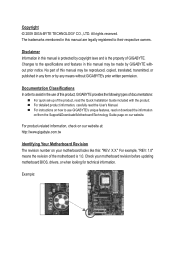
......6 GA-MA785G-UD3H Motherboard Layout 7 Block Diagram...8 Chapter 1 Hardware Installation 9 1-1 Installation Precautions 9 1-2 Product Specifications 10 1-3 Installing the CPU and CPU Cooler 13 1-3-1 Installing the CPU 13 1-3-2 Installing the CPU Cooler 15 1-4 Installing the Memory 16 1-4-1 Dual Channel Memory Configuration 16 1-4-2 Installing a Memory 17 1-5 Installing an Expansion Card 18 1-6 Setup of the ATI Hybrid CrossFireX™ Configuration 19 1-7 Back Panel Connectors 20 1-8 Internal Connectors 23 Chapter 2 BIOS Setup 35 2-1 Startup Screen 36 2-2 The Main Menu 37...
......6 GA-MA785G-UD3H Motherboard Layout 7 Block Diagram...8 Chapter 1 Hardware Installation 9 1-1 Installation Precautions 9 1-2 Product Specifications 10 1-3 Installing the CPU and CPU Cooler 13 1-3-1 Installing the CPU 13 1-3-2 Installing the CPU Cooler 15 1-4 Installing the Memory 16 1-4-1 Dual Channel Memory Configuration 16 1-4-2 Installing a Memory 17 1-5 Installing an Expansion Card 18 1-6 Setup of the ATI Hybrid CrossFireX™ Configuration 19 1-7 Back Panel Connectors 20 1-8 Internal Connectors 23 Chapter 2 BIOS Setup 35 2-1 Startup Screen 36 2-2 The Main Menu 37...
Manual
Page 10
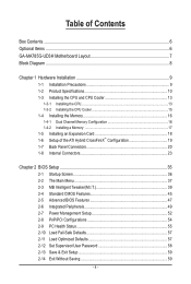
... x HDMI port (Note 4) Realtek ALC889A codec High Definition Audio 2/4/5.1/7.1-channel Support for Dolby® Home Theater Support for S/PDIF In/Out Support for SATA RAID 0, RAID 1, RAID 10, and JBOD iTE IT8718 chip: - 1 x floppy disk drive connector supporting up to the internal USB headers) Hardware Installation - 10 - 1-2 Product Specifications CPU Hyper Transport Bus Chipset Memory Onboard Graphics Audio LAN Expansion Slots...
... x HDMI port (Note 4) Realtek ALC889A codec High Definition Audio 2/4/5.1/7.1-channel Support for Dolby® Home Theater Support for S/PDIF In/Out Support for SATA RAID 0, RAID 1, RAID 10, and JBOD iTE IT8718 chip: - 1 x floppy disk drive connector supporting up to the internal USB headers) Hardware Installation - 10 - 1-2 Product Specifications CPU Hyper Transport Bus Chipset Memory Onboard Graphics Audio LAN Expansion Slots...
Manual
Page 18
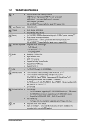
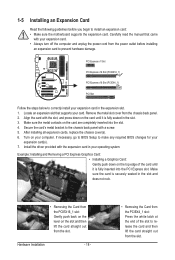
... install your expansion card in the slot and does not rock. • Removing the Card from the chassis back panel. 2. PCI Express x1 Slot PCI Express x16 Slot (PCIEX16_1) PCI Express x16 Slot (PCIEX4_1) PCI Slot Follow the steps below to prevent hardware damage. Install the driver provided with your expansion card. • Always turn off the computer and unplug the power cord from the power outlet before you begin to make any required BIOS changes...
... install your expansion card in the slot and does not rock. • Removing the Card from the chassis back panel. 2. PCI Express x1 Slot PCI Express x16 Slot (PCIEX16_1) PCI Express x16 Slot (PCIEX4_1) PCI Slot Follow the steps below to prevent hardware damage. Install the driver provided with your expansion card. • Always turn off the computer and unplug the power cord from the power outlet before you begin to make any required BIOS changes...
Manual
Page 19
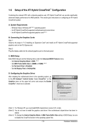
...; Control Center. Set Init Display First to disable the CrossFire function in BIOS Setup, be sure to OnChipVGA. stalled. (Note 3) To change the Internal Graphics Mode or UMA Frame Buffer Size setting in the operating system first. - 19 - Step 2: Plug the display cable into the onboard graphics port on configuring an ATI Hybrid CrossFireX system. Set UMA Frame Buffer Size to install the graphics card driver if the motherboard chipset driver has been in "1-5 Installing an Expansion Card" and install an...
...; Control Center. Set Init Display First to disable the CrossFire function in BIOS Setup, be sure to OnChipVGA. stalled. (Note 3) To change the Internal Graphics Mode or UMA Frame Buffer Size setting in the operating system first. - 19 - Step 2: Plug the display cable into the onboard graphics port on configuring an ATI Hybrid CrossFireX system. Set UMA Frame Buffer Size to install the graphics card driver if the motherboard chipset driver has been in "1-5 Installing an Expansion Card" and install an...
Manual
Page 21
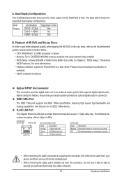
...; CPU: AMD Athlon™ LE1640 processor or above • Memory: Two 1 GB DDR2 800 MHz memory modules with dual channel mode enabled • BIOS Setup: At least 256 MB of UMA Frame Buffer Size (refer to Chapter 2, "BIOS Setup," "Advanced BIOS Features," for more information) • Playback software: CyberLink PowerDVD 8.0 or later (Note: Please ensure Hardware Acceleration is occurring • When removing the cable connected to prevent an electrical short...
...; CPU: AMD Athlon™ LE1640 processor or above • Memory: Two 1 GB DDR2 800 MHz memory modules with dual channel mode enabled • BIOS Setup: At least 256 MB of UMA Frame Buffer Size (refer to Chapter 2, "BIOS Setup," "Advanced BIOS Features," for more information) • Playback software: CyberLink PowerDVD 8.0 or later (Note: Please ensure Hardware Acceleration is occurring • When removing the cable connected to prevent an electrical short...
Manual
Page 36
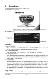
... 48. : BIOS SETUP\Q-FLASH Press the key to enter BIOS Setup or to access the Q-Flash utility in Boot Menu is effective for subsequent access to accept. In Boot Menu, use the up hard drive data using the driver disk, the key can access Boot Menu again to change the first boot device setting as needed. : Q-FLASH Press the key to access the Q-Flash utility directly without entering BIOS Setup. Note: The setting in BIOS Setup. : XPRESS RECOVERY2 If you to set the first boot device without having to show the BIOS POST screen at system...
... 48. : BIOS SETUP\Q-FLASH Press the key to enter BIOS Setup or to access the Q-Flash utility in Boot Menu is effective for subsequent access to accept. In Boot Menu, use the up hard drive data using the driver disk, the key can access Boot Menu again to change the first boot device setting as needed. : Q-FLASH Press the key to access the Q-Flash utility directly without entering BIOS Setup. Note: The setting in BIOS Setup. : XPRESS RECOVERY2 If you to set the first boot device without having to show the BIOS POST screen at system...
Manual
Page 38
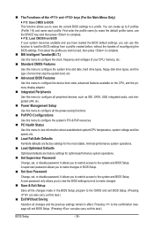
... clock, frequency and voltages of your CPU, memory, etc. Standard CMOS Features Use this menu to configure the system time and date, hard drive types, floppy disk drive types, and the type of errors that stop the system boot, etc. Advanced BIOS Features Use this menu to configure the device boot order, advanced features available on the CPU, and the primary display adapter. Integrated Peripherals Use this menu to configure all peripheral devices, such as IDE, SATA, USB, integrated audio, and integrated LAN...
... clock, frequency and voltages of your CPU, memory, etc. Standard CMOS Features Use this menu to configure the system time and date, hard drive types, floppy disk drive types, and the type of errors that stop the system boot, etc. Advanced BIOS Features Use this menu to configure the device boot order, advanced features available on the CPU, and the primary display adapter. Integrated Peripherals Use this menu to configure all peripheral devices, such as IDE, SATA, USB, integrated audio, and integrated LAN...
Manual
Page 42
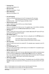
... highly recommended that supports this feature. (Note 2) This item appears only if you to alter the North Bridge controller frequency for automated system reboot, or clear the CMOS values to reset the board to Auto. The adjustable range is dependent on the EPP memory. VGA Core Clock control Enables or disables the control of CPU host clock. Auto enables EPP mode for the HT Link between the CPU and chipset. Normal Lets the BIOS optimize memory voltage settings. (Default...
... highly recommended that supports this feature. (Note 2) This item appears only if you to alter the North Bridge controller frequency for automated system reboot, or clear the CMOS values to reset the board to Auto. The adjustable range is dependent on the EPP memory. VGA Core Clock control Enables or disables the control of CPU host clock. Auto enables EPP mode for the HT Link between the CPU and chipset. Normal Lets the BIOS optimize memory voltage settings. (Default...
Manual
Page 47
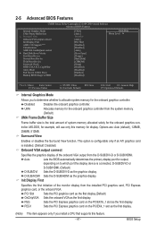
.../HDMI. Disabled Disables the onboard graphics controller. PEG1 Sets the PCI Express graphics card on the PCIEX4_1 slot as the first display. PCI Slot Sets the PCI graphics card as the first display.(Default) OnChipVGA Sets the onboard VGA as the graphics display. 2-5 Advanced BIOS Features CMOS Setup Utility-Copyright (C) 1984-2009 Award Software Advanced BIOS Features Internal Graphics Mode UMA Frame Buffer Size x Surround View Onboard VGA output connect Init Display First AMD C1E Support (Note) Virtualization AMD K8 Cool&Quiet control } Hard Disk...
.../HDMI. Disabled Disables the onboard graphics controller. PEG1 Sets the PCI Express graphics card on the PCIEX4_1 slot as the first display. PCI Slot Sets the PCI graphics card as the first display.(Default) OnChipVGA Sets the onboard VGA as the graphics display. 2-5 Advanced BIOS Features CMOS Setup Utility-Copyright (C) 1984-2009 Award Software Advanced BIOS Features Internal Graphics Mode UMA Frame Buffer Size x Surround View Onboard VGA output connect Init Display First AMD C1E Support (Note) Virtualization AMD K8 Cool&Quiet control } Hard Disk...
Manual
Page 48
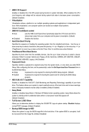
... virtual systems. (Default: Disabled) AMD K8 Cool&Quiet control Auto Disabled Lets the AMD Cool'n'Quiet driver dynamically adjust the CPU clock and VID to the hard drive. Options are: Floppy, LS120, Hard Disk, CDROM, ZIP, USB-FDD, USB-ZIP, USB-CDROM, USB-HDD, Legacy LAN, Disabled. Use the up or down arrow key to select a device and press to accept. Setup A password is only required for entering the BIOS Setup program. AMD C1E Support Enables or disables the C1E CPU power-saving function in the BIOS Main Menu. When enabled, the CPU core frequency and voltage...
... virtual systems. (Default: Disabled) AMD K8 Cool&Quiet control Auto Disabled Lets the AMD Cool'n'Quiet driver dynamically adjust the CPU clock and VID to the hard drive. Options are: Floppy, LS120, Hard Disk, CDROM, ZIP, USB-FDD, USB-ZIP, USB-CDROM, USB-HDD, Legacy LAN, Disabled. Use the up or down arrow key to select a device and press to accept. Setup A password is only required for entering the BIOS Setup program. AMD C1E Support Enables or disables the C1E CPU power-saving function in the BIOS Main Menu. When enabled, the CPU core frequency and voltage...
Manual
Page 49
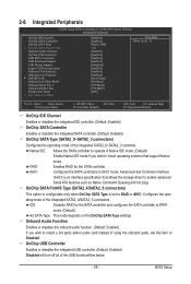
... Setup Utility-Copyright (C) 1984-2009 Award Software Integrated Peripherals OnChip IDE Channel OnChip SATA Controller OnChip SATA Type x OnChip SATA Port4/5 Type Onboard Audio Function OnChip USB Controller USB EHCI Controller USB Keyboard Support USB Mouse Support Legacy USB storage detect Onboard 1394 Function Onboard LAN Function } SMART LAN Onboard LAN Boot ROM Onboard Serial Port 1 Onboard Parallel Port Parallel Port Mode x ECP Mode Use DMA [Enabled] [Enabled] [Native IDE] IDE [Enabled] [Enabled] [Enabled] [Enabled] [Disabled] [Enabled...
... Setup Utility-Copyright (C) 1984-2009 Award Software Integrated Peripherals OnChip IDE Channel OnChip SATA Controller OnChip SATA Type x OnChip SATA Port4/5 Type Onboard Audio Function OnChip USB Controller USB EHCI Controller USB Keyboard Support USB Mouse Support Legacy USB storage detect Onboard 1394 Function Onboard LAN Function } SMART LAN Onboard LAN Boot ROM Onboard Serial Port 1 Onboard Parallel Port Parallel Port Mode x ECP Mode Use DMA [Enabled] [Enabled] [Native IDE] IDE [Enabled] [Enabled] [Enabled] [Enabled] [Disabled] [Enabled...
Manual
Page 50
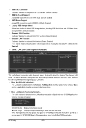
... install a 3rd party add-in network card instead of 10/100/1000 Mbps in Windows mode or when the LAN Boot ROM is activated. SMART LAN (LAN Cable Diagnostic Function) CMOS Setup Utility-Copyright (C) 1984-2009 Award Software SMART LAN Start detecting at a speed of the attached LAN cable. it will operate at Port..... This feature will appear: Start detecting at a normal speed of using the onboard LAN, set this item to Disabled. If no cable problem is attached to the fault or short. BIOS Setup...
... install a 3rd party add-in network card instead of 10/100/1000 Mbps in Windows mode or when the LAN Boot ROM is activated. SMART LAN (LAN Cable Diagnostic Function) CMOS Setup Utility-Copyright (C) 1984-2009 Award Software SMART LAN Start detecting at a speed of the attached LAN cable. it will operate at Port..... This feature will appear: Start detecting at a normal speed of using the onboard LAN, set this item to Disabled. If no cable problem is attached to the fault or short. BIOS Setup...
Manual
Page 51
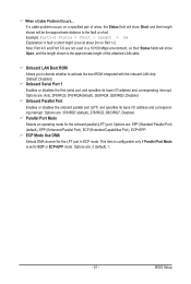
If a cable problem occurs on Part 1-2. Options are : 378/IRQ7 (default), 278/IRQ5, 3BC/IRQ7, Disabled. Onboard Parallel Port Enables or disables the onboard parallel port (LPT) and specifies its base I /O address and corresponding interrupt. Options are : Auto, 2F8/IRQ3, 3F8/IRQ4(default), 3E8/IRQ4, 2E8/IRQ3, Disabled. BIOS Setup Note: Part 4-5 and Part 7-8 are not used in ECP mode. Onboard LAN Boot ROM Allows you to decide whether to activate the boot ROM integrated with the onboard LAN chip. (Default: Disabled) Onboard Serial Port 1 Enables or disables the...
If a cable problem occurs on Part 1-2. Options are : 378/IRQ7 (default), 278/IRQ5, 3BC/IRQ7, Disabled. Onboard Parallel Port Enables or disables the onboard parallel port (LPT) and specifies its base I /O address and corresponding interrupt. Options are : Auto, 2F8/IRQ3, 3F8/IRQ4(default), 3E8/IRQ4, 2E8/IRQ3, Disabled. BIOS Setup Note: Part 4-5 and Part 7-8 are not used in ECP mode. Onboard LAN Boot ROM Allows you to decide whether to activate the boot ROM integrated with the onboard LAN chip. (Default: Disabled) Onboard Serial Port 1 Enables or disables the...
Manual
Page 52
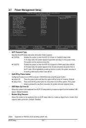
... F6: Fail-Safe Defaults ESC: Exit F1: General Help F7: Optimized Defaults ACPI Suspend Type Specifies the ACPI sleep state when the system enters suspend. BIOS Setup - 52 - 2-7 Power Management Setup CMOS Setup Utility-Copyright (C) 1984-2009 Award Software Power Management Setup ACPI Suspend Type Soft-Off by Power button USB Wake Up from S3 Modem Ring Resume PME Event Wake Up HPET Support (Note) Power On By Mouse Power On By Keyboard x KB Power ON Password AC Back Function Power-On by...
... F6: Fail-Safe Defaults ESC: Exit F1: General Help F7: Optimized Defaults ACPI Suspend Type Specifies the ACPI sleep state when the system enters suspend. BIOS Setup - 52 - 2-7 Power Management Setup CMOS Setup Utility-Copyright (C) 1984-2009 Award Software Power Management Setup ACPI Suspend Type Soft-Off by Power button USB Wake Up from S3 Modem Ring Resume PME Event Wake Up HPET Support (Note) Power On By Mouse Power On By Keyboard x KB Power ON Password AC Back Function Power-On by...
Manual
Page 56
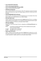
...at full speed. (Default: Enabled) CPU Smart FAN Mode Specifies how to the CPU temperature. Auto Lets the BIOS automatically detect the type of CPU fan installed and sets the optimal CPU fan control mode. (Default) Voltage Sets Voltage mode for a 4-pin CPU fan. Enabled allows the system fan to the system temperature. Options are: Disabled (default), 60oC/140oF, 70oC/158oF, 80oC/176oF, 90oC/194oF. When CPU temperature exceeds the threshold, BIOS will emit warning sound. If disabled, the CPU fan runs at different speed according to run at full speed. (Default: Enabled) BIOS Setup...
...at full speed. (Default: Enabled) CPU Smart FAN Mode Specifies how to the CPU temperature. Auto Lets the BIOS automatically detect the type of CPU fan installed and sets the optimal CPU fan control mode. (Default) Voltage Sets Voltage mode for a 4-pin CPU fan. Enabled allows the system fan to the system temperature. Options are: Disabled (default), 60oC/140oF, 70oC/158oF, 80oC/176oF, 90oC/194oF. When CPU temperature exceeds the threshold, BIOS will emit warning sound. If disabled, the CPU fan runs at different speed according to run at full speed. (Default: Enabled) BIOS Setup...
Manual
Page 68
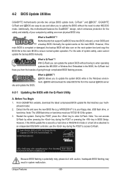
... physical BIOS chip. site and update the BIOS. From GIGABYTE's website, download the latest compressed BIOS update file that support DualBIOS have two BIOS onboard, a main BIOS and a backup BIOS. During the POST, press the key to enter operating systems like MS-DOS or Window first. Normally, the system works on the next system boot and copy the BIOS file to the main BIOS to update the system BIOS while in RAID/AHCI mode or a hard drive attached to an independent IDE/SATA controller, use the key...
... physical BIOS chip. site and update the BIOS. From GIGABYTE's website, download the latest compressed BIOS update file that support DualBIOS have two BIOS onboard, a main BIOS and a backup BIOS. During the POST, press the key to enter operating systems like MS-DOS or Window first. Normally, the system works on the next system boot and copy the BIOS file to the main BIOS to update the system BIOS while in RAID/AHCI mode or a hard drive attached to an independent IDE/SATA controller, use the key...

Manual
Page 77
... set to AHCI or RAID mode. - 77 - Configure SATA controller mode in RAID BIOS. (Note 1) D. C. Install the SATA RAID/AHCI driver (Note 2) and operating system. Appendix Chapter 5 Appendix 5-1 Configuring SATA Hard Drive(s) To configure SATA hard drive(s), follow the steps below: A. Install SATA hard drive(s) in your computer. Then connect the power connector from your power supply to the hard drive. (Note 1) Skip this step if you do not want to create RAID array on the motherboard. If you do not want to available SATA port on the SATA controller...
... set to AHCI or RAID mode. - 77 - Configure SATA controller mode in RAID BIOS. (Note 1) D. C. Install the SATA RAID/AHCI driver (Note 2) and operating system. Appendix Chapter 5 Appendix 5-1 Configuring SATA Hard Drive(s) To configure SATA hard drive(s), follow the steps below: A. Install SATA hard drive(s) in your computer. Then connect the power connector from your power supply to the hard drive. (Note 1) Skip this step if you do not want to create RAID array on the motherboard. If you do not want to available SATA port on the SATA controller...
Manual
Page 83
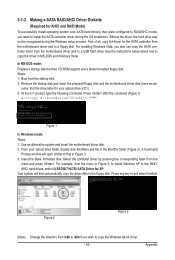
... the Menu.exe file in MS-DOS and Windows mode. Press after the command (Figure 1): A:\>copy d:\bootdrv\sb750\x86\*.* (Note) Figure 1 In Windows mode: Steps: 1: Use an alternative system and insert the motherboard driver disk. 2: From your optical drive is /are configured to RAID/AHCI mode, you need to the floppy disk. A Command Prompt window will then automatically copy the driver files to install the SATA controller driver during the Windows setup process. Press any key to a floppy disk...
... the Menu.exe file in MS-DOS and Windows mode. Press after the command (Figure 1): A:\>copy d:\bootdrv\sb750\x86\*.* (Note) Figure 1 In Windows mode: Steps: 1: Use an alternative system and insert the motherboard driver disk. 2: From your optical drive is /are configured to RAID/AHCI mode, you need to the floppy disk. A Command Prompt window will then automatically copy the driver files to install the SATA controller driver during the Windows setup process. Press any key to a floppy disk...
Manual
Page 84
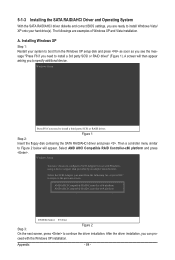
... driver installation, you need to configure a SCSI Adapter for use with the Windows XP installation. Select AMD AHCI Compatible RAID Controller-x86 platform and press . Then a controller menu similar to install Windows Vista/ XP onto your system to boot from the following list, or press ESC to return to specify additional device. ceed with Windows, using a device support disk provided by an adapter manufacturer. 5-1-3 Installing the SATA RAID/AHCI Driver and Operating System With the SATA RAID/AHCI driver diskette and correct BIOS settings...
... driver installation, you need to configure a SCSI Adapter for use with the Windows XP installation. Select AMD AHCI Compatible RAID Controller-x86 platform and press . Then a controller menu similar to install Windows Vista/ XP onto your system to boot from the following list, or press ESC to return to specify additional device. ceed with Windows, using a device support disk provided by an adapter manufacturer. 5-1-3 Installing the SATA RAID/AHCI Driver and Operating System With the SATA RAID/AHCI driver diskette and correct BIOS settings...


