
Manual
Page 3
... The revision number on your motherboard revision before updating motherboard BIOS, drivers, or when looking for technical information. Check your motherboard looks like this product, GIGABYTE provides the following types of documentations: For quick set-up of the motherboard is protected by GIGABYTE without GIGABYTE's prior written permission. For instructions on our website. All...
... The revision number on your motherboard revision before updating motherboard BIOS, drivers, or when looking for technical information. Check your motherboard looks like this product, GIGABYTE provides the following types of documentations: For quick set-up of the motherboard is protected by GIGABYTE without GIGABYTE's prior written permission. For instructions on our website. All...

Manual
Page 4
Table of Contents Box Contents...6 Optional Items...6 GA-MA770-ES3 Motherboard Layout 7 GA-MA770-ES3 Motherboard Block Diagram 8 Chapter 1 Hardware Installation 9 1-1 Installation Precautions 9 1-2 Product Specifications 10 1-3 Installing the CPU and CPU ... an Expansion Card 18 1-6 Back Panel Connectors 19 1-7 Internal Connectors 21 Chapter 2 BIOS Setup 31 2-1 Startup Screen 32 2-2 The Main Menu 33 2-3 MB Intelligent Tweaker(M.I.T 35 2-4 Standard CMOS Features 40 2-5 Advanced BIOS Features 42 2-6 Integrated Peripherals 44 2-7 Power Management Setup 47 2-8 PC Health Status ...
Table of Contents Box Contents...6 Optional Items...6 GA-MA770-ES3 Motherboard Layout 7 GA-MA770-ES3 Motherboard Block Diagram 8 Chapter 1 Hardware Installation 9 1-1 Installation Precautions 9 1-2 Product Specifications 10 1-3 Installing the CPU and CPU ... an Expansion Card 18 1-6 Back Panel Connectors 19 1-7 Internal Connectors 21 Chapter 2 BIOS Setup 31 2-1 Startup Screen 32 2-2 The Main Menu 33 2-3 MB Intelligent Tweaker(M.I.T 35 2-4 Standard CMOS Features 40 2-5 Advanced BIOS Features 42 2-6 Integrated Peripherals 44 2-7 Power Management Setup 47 2-8 PC Health Status ...

Manual
Page 5
... 56 3-3 Technical Manuals 56 3-4 Contact...57 3-5 System...57 3-6 Download Center 58 Chapter 4 Unique Features 59 4-1 Xpress Recovery2 59 4-2 BIOS Update Utilities 62 4-2-1 Updating the BIOS with the Q-Flash Utility 62 4-2-2 Updating the BIOS with the @BIOS Utility 65 4-3 EasyTune 6...66 4-4 Easy Energy Saver 67 4-5 Q-Share...69 4-6 SMART Recovery 70 Chapter 5 Appendix...71 5-1 Configuring SATA...
... 56 3-3 Technical Manuals 56 3-4 Contact...57 3-5 System...57 3-6 Download Center 58 Chapter 4 Unique Features 59 4-1 Xpress Recovery2 59 4-2 BIOS Update Utilities 62 4-2-1 Updating the BIOS with the Q-Flash Utility 62 4-2-2 Updating the BIOS with the @BIOS Utility 65 4-3 EasyTune 6...66 4-4 Easy Energy Saver 67 4-5 Q-Share...69 4-6 SMART Recovery 70 Chapter 5 Appendix...71 5-1 Configuring SATA...

Manual
Page 8
GA-MA770-ES3 Motherboard Block Diagram CPU CLK+/- (200 MHz) PCIe CLK (100 MHz) AM3/AM2+/AM2 CPU DDR2 1200(O.C.)/1066(Note)/800 MHz Dual Channel Memory 1 PCI ... Hyper Transport 3.0 PCI Express x16 PCI Express Bus PCIe CLK (100 MHz) x1 x1 x1 x1 4 PCI Express x1 RTL8111D RJ45 LAN PCI Bus Dual BIOS AMD 770 12 USB Ports AMD SB710 ATA-133/100/66/33 IDE Channel 6 SATA 3Gb/s CODEC LPC Bus IT8720 Floppy LPT Port COM Port...
GA-MA770-ES3 Motherboard Block Diagram CPU CLK+/- (200 MHz) PCIe CLK (100 MHz) AM3/AM2+/AM2 CPU DDR2 1200(O.C.)/1066(Note)/800 MHz Dual Channel Memory 1 PCI ... Hyper Transport 3.0 PCI Express x16 PCI Express Bus PCIe CLK (100 MHz) x1 x1 x1 x1 4 PCI Express x1 RTL8111D RJ45 LAN PCI Bus Dual BIOS AMD 770 12 USB Ports AMD SB710 ATA-133/100/66/33 IDE Channel 6 SATA 3Gb/s CODEC LPC Bus IT8720 Floppy LPT Port COM Port...

Manual
Page 11
... port w 1 x serial port w 1 x coaxial S/PDIF Out connector w 8 x USB 2.0/1.1 ports w 1 x RJ-45 port w 3 x audio jacks (Line In/Line Out/Microphone) I/O Controller w iTE IT8720 chip Hardware Monitor w w w w w w BIOS w w w w System voltage detection CPU/System temperature detection CPU/System/Power fan speed detection CPU overheating warning CPU/System/Power fan fail warning CPU/System fan...
... port w 1 x serial port w 1 x coaxial S/PDIF Out connector w 8 x USB 2.0/1.1 ports w 1 x RJ-45 port w 3 x audio jacks (Line In/Line Out/Microphone) I/O Controller w iTE IT8720 chip Hardware Monitor w w w w w w BIOS w w w w System voltage detection CPU/System temperature detection CPU/System/Power fan speed detection CPU overheating warning CPU/System/Power fan fail warning CPU/System fan...

Manual
Page 12
Hardware Installation - 12 - Unique Features w w w w w w w w w w Bundled Software w Support for @BIOS Support for Q-Flash Support for Xpress BIOS Rescue Support for Download Center Support for Xpress Install Support for Xpress Recovery2 Support for EasyTune (Note 6) Support for Easy Energy Saver (Note 7) Support for ...
Hardware Installation - 12 - Unique Features w w w w w w w w w w Bundled Software w Support for @BIOS Support for Q-Flash Support for Xpress BIOS Rescue Support for Download Center Support for Xpress Install Support for Xpress Recovery2 Support for EasyTune (Note 6) Support for Easy Energy Saver (Note 7) Support for ...

Manual
Page 16
...Installation - 16 - After the memory is recommended that the motherboard supports the memory. Dual Channel mode cannot be used . (Go to GIGABYTE's website for the latest memory support list.) • Always turn off the computer and unplug the power cord from the power outlet before... damage. • Memory modules have a foolproof design. When enabling Dual Channel mode with two memory modules, it is installed, the BIOS will double the original memory bandwidth. Enabling Dual Channel memory mode will automatically detect the specifications and capacity of the same capacity, brand,...
...Installation - 16 - After the memory is recommended that the motherboard supports the memory. Dual Channel mode cannot be used . (Go to GIGABYTE's website for the latest memory support list.) • Always turn off the computer and unplug the power cord from the power outlet before... damage. • Memory modules have a foolproof design. When enabling Dual Channel mode with two memory modules, it is installed, the BIOS will double the original memory bandwidth. Enabling Dual Channel memory mode will automatically detect the specifications and capacity of the same capacity, brand,...

Manual
Page 18
... on the slot and then lift the card straight out from the slot. Align the card with a screw. 5. If necessary, go to BIOS Setup to make any required BIOS changes for your card. After installing all expansion cards, replace the chassis cover(s). 6. Locate an expansion slot that came with the expansion card...
... on the slot and then lift the card straight out from the slot. Align the card with a screw. 5. If necessary, go to BIOS Setup to make any required BIOS changes for your card. After installing all expansion cards, replace the chassis cover(s). 6. Locate an expansion slot that came with the expansion card...

Manual
Page 25
...; RES (Reset Switch, Green): Connects to the reset switch on the chassis front panel. The LED is off when the system is detected, the BIOS may issue beeps in S3/S4 sleep S3/S4/S5 Off state or powered off your chassis front panel module to this header according to...pin assignments are matched correctly. - 25 - PW+ PWSPEAK+ SPEAK- 2 20 1 19 HD+ HD- When connecting your system using the power switch (refer to Chapter 2, "BIOS Setup," "Power Management Setup," for information about beep codes. • HD (Hard Drive Activity LED, Blue) Connects to the hard drive activity LED on the...
...; RES (Reset Switch, Green): Connects to the reset switch on the chassis front panel. The LED is off when the system is detected, the BIOS may issue beeps in S3/S4 sleep S3/S4/S5 Off state or powered off your chassis front panel module to this header according to...pin assignments are matched correctly. - 25 - PW+ PWSPEAK+ SPEAK- 2 20 1 19 HD+ HD- When connecting your system using the power switch (refer to Chapter 2, "BIOS Setup," "Power Management Setup," for information about beep codes. • HD (Hard Drive Activity LED, Blue) Connects to the hard drive activity LED on the...

Manual
Page 28
.... • Always turn off your computer and unplug the power cord. 2. Replace the battery when the battery voltage drops to keep the values (such as BIOS configurations, date, and time information) in accordance with an equivalent one minute. (Or use a metal object like a screwdriver to touch the positive and negative terminals...
.... • Always turn off your computer and unplug the power cord. 2. Replace the battery when the battery voltage drops to keep the values (such as BIOS configurations, date, and time information) in accordance with an equivalent one minute. (Or use a metal object like a screwdriver to touch the positive and negative terminals...

Manual
Page 29
... to do so may cause damage to the motherboard. • After system restart, go to BIOS Setup to load factory defaults (select Load Optimized Defaults) or manually configure the BIOS settings (refer to remove the jumper cap from the power outlet before clearing the CMOS values. ...the CMOS values, place a jumper cap on your computer, be sure to Chapter 2, "BIOS Setup," for a few seconds. date information and BIOS configurations) and reset the CMOS values to touch the two pins for BIOS configurations). - 29 - Hardware Installation 16) CLR_CMOS (Clearing CMOS Jumper) Use this jumper...
... to do so may cause damage to the motherboard. • After system restart, go to BIOS Setup to load factory defaults (select Load Optimized Defaults) or manually configure the BIOS settings (refer to remove the jumper cap from the power outlet before clearing the CMOS values. ...the CMOS values, place a jumper cap on your computer, be sure to Chapter 2, "BIOS Setup," for a few seconds. date information and BIOS configurations) and reset the CMOS values to touch the two pins for BIOS configurations). - 29 - Hardware Installation 16) CLR_CMOS (Clearing CMOS Jumper) Use this jumper...

Manual
Page 31
... the power is turned off, the battery on using the current version of the BIOS Setup program. To upgrade the BIOS, use either the GIGABYTE Q-Flash or @BIOS utility. • Q-Flash allows the user to Chapter 4, "BIOS Update Utilities." • Because BIOS flashing is potentially risky, if you do it is a Windows-based utility that allows...
... the power is turned off, the battery on using the current version of the BIOS Setup program. To upgrade the BIOS, use either the GIGABYTE Q-Flash or @BIOS utility. • Q-Flash allows the user to Chapter 4, "BIOS Update Utilities." • Because BIOS flashing is potentially risky, if you do it is a Windows-based utility that allows...

Manual
Page 32
...used for GA-MA770-ES3 D2 . . . . : BIOS Setup : XpressRecovery2 : Boot Menu : Qflash 10/20/2009-RX780-SB710-7A66AG0PC-00 Function Keys Function Keys: : POST SCREEN Press the key to show the BIOS POST screen at system startup, refer to the instructions on the Full Screen LOGO Show item on BIOS Setup settings... access Boot Menu again to change the first boot device setting as needed. : Q-FLASH Press the key to enter BIOS Setup first. Note: The setting in BIOS Setup. : XPRESS RECOVERY2 If you to set the first boot device without having to access the Q-Flash utility directly without...
...used for GA-MA770-ES3 D2 . . . . : BIOS Setup : XpressRecovery2 : Boot Menu : Qflash 10/20/2009-RX780-SB710-7A66AG0PC-00 Function Keys Function Keys: : POST SCREEN Press the key to show the BIOS POST screen at system startup, refer to the instructions on the Full Screen LOGO Show item on BIOS Setup settings... access Boot Menu again to change the first boot device setting as needed. : Q-FLASH Press the key to enter BIOS Setup first. Note: The setting in BIOS Setup. : XPRESS RECOVERY2 If you to set the first boot device without having to access the Q-Flash utility directly without...

Manual
Page 33
... to select an item Execute command or enter the submenu Main Menu: Exit the BIOS Setup program Submenus: Exit current submenu Increase the numeric value or make changes Decrease ... Select Item F10: Save & Exit Setup Change CPU's Clock & Voltage F11: Save CMOS to BIOS F12: Load CMOS from BIOS Main Menu Help The on-screen description of a highlighted setup option is displayed on the screen. ... right side of the submenu. • If you do not find the settings you enter the BIOS Setup program, the Main Menu (as shown below) appears on the bottom line of function keys...
... to select an item Execute command or enter the submenu Main Menu: Exit the BIOS Setup program Submenus: Exit current submenu Increase the numeric value or make changes Decrease ... Select Item F10: Save & Exit Setup Change CPU's Clock & Voltage F11: Save CMOS to BIOS F12: Load CMOS from BIOS Main Menu Help The on-screen description of a highlighted setup option is displayed on the screen. ... right side of the submenu. • If you do not find the settings you enter the BIOS Setup program, the Main Menu (as shown below) appears on the bottom line of function keys...
Manual
Page 34
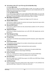
...and date, hard drive types, floppy disk drive types, and the type of errors that stop the system boot, etc. Advanced BIOS Features Use this menu to configure the device boot order, advanced features available on the CPU, and the primary display adapter. ...password. It allows you to restrict access to the confirmation message will exit BIOS Setup. (Pressing can create up to the system and BIOS Setup. The Functions of reconfiguring the BIOS settings. Pressing to the system and BIOS Setup. A supervisor password allows you to restrict access to 8 profiles (...
...and date, hard drive types, floppy disk drive types, and the type of errors that stop the system boot, etc. Advanced BIOS Features Use this menu to configure the device boot order, advanced features available on the CPU, and the primary display adapter. ...password. It allows you to restrict access to the confirmation message will exit BIOS Setup. (Pressing can create up to the system and BIOS Setup. The Functions of reconfiguring the BIOS settings. Pressing to the system and BIOS Setup. A supervisor password allows you to restrict access to 8 profiles (...

Manual
Page 35
BIOS Setup Advanced Clock Calibration CMOS Setup Utility-Copyright (C) 1984-2009 Award Software Advanced Clock Calibration EC Firmware Selection Advanced Clock Calibration x Value (All Cores) x Value (...
BIOS Setup Advanced Clock Calibration CMOS Setup Utility-Copyright (C) 1984-2009 Award Software Advanced Clock Calibration EC Firmware Selection Advanced Clock Calibration x Value (All Cores) x Value (...
Manual
Page 36
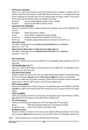
...the PCIe clock frequency to standard 100 MHz. (Default: Auto) HT Link Frequency Allows you install a CPU that the CPU frequency be configurable. BIOS Setup - 36 - EC Firmware Selection Allows you to alter the North Bridge controller frequency for the installed CPU. Wait for the installed CPU. ... system reboot, or clear the CMOS values to reset the board to automatically adjust the CPU host frequency. Auto (default) allows the BIOS to default values. Important It is dependent on the CPU being used . Set Memory Clock Determines whether to enable Advanced Clock Calibration when...
...the PCIe clock frequency to standard 100 MHz. (Default: Auto) HT Link Frequency Allows you install a CPU that the CPU frequency be configurable. BIOS Setup - 36 - EC Firmware Selection Allows you to alter the North Bridge controller frequency for the installed CPU. Wait for the installed CPU. ... system reboot, or clear the CMOS values to reset the board to automatically adjust the CPU host frequency. Auto (default) allows the BIOS to default values. Important It is dependent on the CPU being used . Set Memory Clock Determines whether to enable Advanced Clock Calibration when...
Manual
Page 37
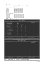
...-Safe Defaults ESC: Exit F1: General Help F7: Optimized Defaults CMOS Setup Utility-Copyright (C) 1984-2009 Award Software MB Intelligent Tweaker(M.I.T.) x RAS to X2.66. BIOS Setup X3.33 Sets Memory Clock to DDR 400.
...-Safe Defaults ESC: Exit F1: General Help F7: Optimized Defaults CMOS Setup Utility-Copyright (C) 1984-2009 Award Software MB Intelligent Tweaker(M.I.T.) x RAS to X2.66. BIOS Setup X3.33 Sets Memory Clock to DDR 400.

Manual
Page 38
...), 3T~6T. TwTr Command Delay Options are : Auto (default), 75ns, 105ns, 127.5ns, 195ns, 327.5ns. Trfc1 for DIMM2 Options are : Auto (default), 11T~26T. BIOS Setup - 38 - Precharge Time Options are : Auto (default), Manual. Ganged Sets memory control mode to be configurable. Unganged Sets memory control mode to two single...
...), 3T~6T. TwTr Command Delay Options are : Auto (default), 75ns, 105ns, 127.5ns, 195ns, 327.5ns. Trfc1 for DIMM2 Options are : Auto (default), 11T~26T. BIOS Setup - 38 - Precharge Time Options are : Auto (default), Manual. Ganged Sets memory control mode to be configurable. Unganged Sets memory control mode to two single...

Manual
Page 39
Auto lets the BIOS automatically set the system voltages as required. The adjustable range is dependent on the CPU being installed. (Default: Normal) Note: Increasing CPU voltage may result ... useful life of the CPU. Normal Supplies the North Bridge voltage as required. CPU Voltage Control Allows you install a CPU that supports this feature. - 39 - BIOS Setup
Auto lets the BIOS automatically set the system voltages as required. The adjustable range is dependent on the CPU being installed. (Default: Normal) Note: Increasing CPU voltage may result ... useful life of the CPU. Normal Supplies the North Bridge voltage as required. CPU Voltage Control Allows you install a CPU that supports this feature. - 39 - BIOS Setup


