
Manual
Page 1
GA-MA74GM-S2H/ GA-MA74GM-S2 AM2+/AM2 socket motherboard for AMD Phenom™ II processor/ AMD Phenom™ processor/ AMD Athlon™ II processor/ AMD Athlon™ processor/ AMD Sempron™ processor User's Manual Rev. 4001 12ME-MA74G2H-4001R
GA-MA74GM-S2H/ GA-MA74GM-S2 AM2+/AM2 socket motherboard for AMD Phenom™ II processor/ AMD Phenom™ processor/ AMD Athlon™ II processor/ AMD Athlon™ processor/ AMD Sempron™ processor User's Manual Rev. 4001 12ME-MA74G2H-4001R

Manual
Page 2
Motherboard GA-MA74GM-S2H/GA-MA74GM-S2 Sept. 7, 2009 Motherboard GA-MA74GM-S2H/ GA-MA74GM-S2 Sept. 7, 2009
Motherboard GA-MA74GM-S2H/GA-MA74GM-S2 Sept. 7, 2009 Motherboard GA-MA74GM-S2H/ GA-MA74GM-S2 Sept. 7, 2009
Manual
Page 3
..."REV: X.X." For product-related information, check on our website at: http://www.gigabyte.com.tw Identifying Your Motherboard Revision The revision number on your motherboard revision before updating motherboard BIOS, drivers, or when looking for technical information. Example: The trademarks mentioned in ...this manual is protected by any form or by copyright laws and is 1.0. Check your motherboard looks like this product, GIGABYTE provides the following types of GIGABYTE. Changes to the specifications and features in this manual are legally registered to their respective ...
..."REV: X.X." For product-related information, check on our website at: http://www.gigabyte.com.tw Identifying Your Motherboard Revision The revision number on your motherboard revision before updating motherboard BIOS, drivers, or when looking for technical information. Example: The trademarks mentioned in ...this manual is protected by any form or by copyright laws and is 1.0. Check your motherboard looks like this product, GIGABYTE provides the following types of GIGABYTE. Changes to the specifications and features in this manual are legally registered to their respective ...

Manual
Page 4
Table of Contents Box Contents...6 Optional Items...6 GA-MA74GM-S2H/GA-MA74GM-S2 Motherboard Layout 7 Block Diagram...8 Chapter 1 Hardware Installation 9 1-1 Installation Precautions 9 1-2 Product Specifications 10 1-3 Installing the CPU and CPU Cooler 13 1-3-1 Installing the CPU 13 1-3-2 Installing the CPU ...
Table of Contents Box Contents...6 Optional Items...6 GA-MA74GM-S2H/GA-MA74GM-S2 Motherboard Layout 7 Block Diagram...8 Chapter 1 Hardware Installation 9 1-1 Installation Precautions 9 1-2 Product Specifications 10 1-3 Installing the CPU and CPU Cooler 13 1-3-1 Installing the CPU 13 1-3-2 Installing the CPU ...

Manual
Page 6
Box Contents GA-MA74GM-S2H or GA-MA74GM-S2 motherboard Motherboard driver disk User's Manual One IDE cable Two SATA 3Gb/s cables I/O Shield • The box contents above are subject to change without notice. • The motherboard image is for reference only and the actual items shall depend on the product package you obtain. The box contents are for...
Box Contents GA-MA74GM-S2H or GA-MA74GM-S2 motherboard Motherboard driver disk User's Manual One IDE cable Two SATA 3Gb/s cables I/O Shield • The box contents above are subject to change without notice. • The motherboard image is for reference only and the actual items shall depend on the product package you obtain. The box contents are for...

Manual
Page 7
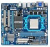
GA-MA74GM-S2H/GA-MA74GM-S2 Motherboard Layout DVI VGA KB(Note)_USB ATX_12V CPU_FAN Socket AM2 M_BIOS B_BIOS ATX IT8718 HDMIj R_USB USB IDE FDD LAN AUDIO F_AUDIO PCIEX1 AMD 740G DDR2_1 DDR2_2 PCIEX16 RTL8111D PCI1 GA-MA74GM-S2H/GA-MA74GM-S2 AMD SB710 CD_IN CODEC PCI2 BAT SATA2_0 COM SATA2_3 SATA2_2 SATA2_1 F_PANEL SPDIF_IO SYS_FAN CLR_CMOS F_USB2 F_USB1 j Only for GA-MA74GM-S2H (Note) Use this port to connect a PS/2 keyboard or PS/2 mouse. - 7 -
GA-MA74GM-S2H/GA-MA74GM-S2 Motherboard Layout DVI VGA KB(Note)_USB ATX_12V CPU_FAN Socket AM2 M_BIOS B_BIOS ATX IT8718 HDMIj R_USB USB IDE FDD LAN AUDIO F_AUDIO PCIEX1 AMD 740G DDR2_1 DDR2_2 PCIEX16 RTL8111D PCI1 GA-MA74GM-S2H/GA-MA74GM-S2 AMD SB710 CD_IN CODEC PCI2 BAT SATA2_0 COM SATA2_3 SATA2_2 SATA2_1 F_PANEL SPDIF_IO SYS_FAN CLR_CMOS F_USB2 F_USB1 j Only for GA-MA74GM-S2H (Note) Use this port to connect a PS/2 keyboard or PS/2 mouse. - 7 -

Manual
Page 9
...• It is best to the use of electrostatic discharge (ESD). Hardware Installation Chapter 1 Hardware Installation 1-1 Installation Precautions The motherboard contains numerous delicate electronic circuits and components which can lead to damage to system components as well as physical harm to the user... wrist strap, keep your hands dry and first touch a metal object to eliminate static electricity. • Prior to installing the motherboard, please have a problem related to wear an electrostatic discharge (ESD) wrist strap when handling electronic com- ponents such as a ...
...• It is best to the use of electrostatic discharge (ESD). Hardware Installation Chapter 1 Hardware Installation 1-1 Installation Precautions The motherboard contains numerous delicate electronic circuits and components which can lead to damage to system components as well as physical harm to the user... wrist strap, keep your hands dry and first touch a metal object to eliminate static electricity. • Prior to installing the motherboard, please have a problem related to wear an electrostatic discharge (ESD) wrist strap when handling electronic com- ponents such as a ...
Manual
Page 12
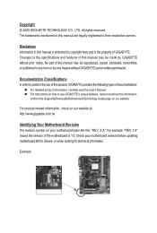
... 5) Whether the CPU fan speed control function is supported will depend on the CPU cooler you install. (Note 6) Available functions in EasyTune may differ by motherboard model.
... 5) Whether the CPU fan speed control function is supported will depend on the CPU cooler you install. (Note 6) Available functions in EasyTune may differ by motherboard model.
Manual
Page 13
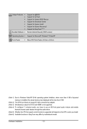
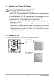
...the system bus frequency be inserted if oriented incorrectly. (Or you wish to set beyond the standard specifications, please do so according to GIGABYTE's website for the peripherals. If you may occur. • Set the CPU host frequency in accordance with the CPU specifications. The CPU... the standard requirements for the latest CPU support list.) • Always turn on the computer if the CPU cooler is not recommended that the motherboard supports the CPU. (Go to your hardware specifications including the CPU, graphics card, memory, hard drive, etc. 1-3-1 Installing the CPU A. ...
...the system bus frequency be inserted if oriented incorrectly. (Or you wish to set beyond the standard specifications, please do so according to GIGABYTE's website for the peripherals. If you may occur. • Set the CPU host frequency in accordance with the CPU specifications. The CPU... the standard requirements for the latest CPU support list.) • Always turn on the computer if the CPU cooler is not recommended that the motherboard supports the CPU. (Go to your hardware specifications including the CPU, graphics card, memory, hard drive, etc. 1-3-1 Installing the CPU A. ...
Manual
Page 14
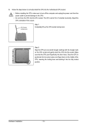
... the CPU orientation if this occurs. The CPU cannot fit in if oriented incorrectly. Follow the steps below to correctly install the CPU into the motherboard CPU socket. • Before installing the CPU, make sure to turn off the computer and unplug the power cord from the power outlet to prevent...
... the CPU orientation if this occurs. The CPU cannot fit in if oriented incorrectly. Follow the steps below to correctly install the CPU into the motherboard CPU socket. • Before installing the CPU, make sure to turn off the computer and unplug the power cord from the power outlet to prevent...

Manual
Page 15
1-3-2 Installing the CPU Cooler Follow the steps below to correctly install the CPU cooler on the CPU. (The following procedure uses the GIGABYTE cooler as the picture above shows) to lock into place. (Refer to your CPU cooler installation manual for instructions on installing the cooler.)...the CPU cooler to the mounting lug on one side of the retention frame. Hardware Installation Step 2: Place the CPU cooler on the motherboard. Inadequately removing the CPU cooler may adhere to the mounting lug on the retention frame. Use extreme care when removing the CPU cooler ...
1-3-2 Installing the CPU Cooler Follow the steps below to correctly install the CPU cooler on the CPU. (The following procedure uses the GIGABYTE cooler as the picture above shows) to lock into place. (Refer to your CPU cooler installation manual for instructions on installing the cooler.)...the CPU cooler to the mounting lug on one side of the retention frame. Hardware Installation Step 2: Place the CPU cooler on the motherboard. Inadequately removing the CPU cooler may adhere to the mounting lug on the retention frame. Use extreme care when removing the CPU cooler ...
Manual
Page 16
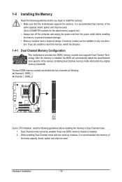
... DDR2 memory sockets are unable to insert the memory, switch the direction. 1-4-1 Dual Channel Memory Configuration This motherboard provides two DDR2 memory sockets and supports Dual Channel Technology. A memory module can be used . (Go to GIGABYTE's website for the latest memory support list.) • Always turn off the computer and unplug the... modules have a foolproof design. 1-4 Installing the Memory Read the following guidelines before installing the memory in only one DDR2 memory module is recommended that the motherboard supports the memory.
... DDR2 memory sockets are unable to insert the memory, switch the direction. 1-4-1 Dual Channel Memory Configuration This motherboard provides two DDR2 memory sockets and supports Dual Channel Technology. A memory module can be used . (Go to GIGABYTE's website for the latest memory support list.) • Always turn off the computer and unplug the... modules have a foolproof design. 1-4 Installing the Memory Read the following guidelines before installing the memory in only one DDR2 memory module is recommended that the motherboard supports the memory.

Manual
Page 17
... retaining clips at both ends of the memory, push down on the socket. Hardware Installation Follow the steps below to install DDR2 DIMMs on this motherboard. Place the memory module on the memory and insert it can only fit in the memory sockets. DDR2 DIMMs are not compatible to DDR DIMMs...
... retaining clips at both ends of the memory, push down on the socket. Hardware Installation Follow the steps below to install DDR2 DIMMs on this motherboard. Place the memory module on the memory and insert it can only fit in the memory sockets. DDR2 DIMMs are not compatible to DDR DIMMs...

Manual
Page 18
... system. After installing all expansion cards, replace the chassis cover(s). 6. If necessary, go to BIOS Setup to install an expansion card: • Make sure the motherboard supports the expansion card. Example: Installing and Removing a PCI Express Graphics Card: • Installing a Graphics Card: Gently push down on the card until it is...
... system. After installing all expansion cards, replace the chassis cover(s). 6. If necessary, go to BIOS Setup to install an expansion card: • Make sure the motherboard supports the expansion card. Example: Installing and Removing a PCI Express Graphics Card: • Installing a Graphics Card: Gently push down on the card until it is...
Manual
Page 20
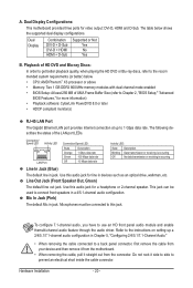
...is occurring Line In Jack (Blue) The default line in a 4/5.1-channel audio configuration. Do not rock it straight out from the motherboard. • When removing the cable, pull it side to side to use an HD front panel audio module and enable themulti-channel.... Use this jack. To configure 7.1-channel audio, you have to prevent an electrical short inside the cable connector. Dual Display Configurations: This motherboard provides three ports for more information) • Playback software: CyberLink PowerDVD 8.0 or later • HDCP compliant monitor(s) RJ-45 LAN Port...
...is occurring Line In Jack (Blue) The default line in a 4/5.1-channel audio configuration. Do not rock it straight out from the motherboard. • When removing the cable, pull it side to side to use an HD front panel audio module and enable themulti-channel.... Use this jack. To configure 7.1-channel audio, you have to prevent an electrical short inside the cable connector. Dual Display Configurations: This motherboard provides three ports for more information) • Playback software: CyberLink PowerDVD 8.0 or later • HDCP compliant monitor(s) RJ-45 LAN Port...

Manual
Page 21
..., make sure your devices are compliant with the connectors you wish to connect. • Before installing the devices, be sure to the connector on the motherboard. - 21 - Hardware Installation Unplug the power cord from the power outlet to prevent damage to the devices. • After installing the device and before connecting...
..., make sure your devices are compliant with the connectors you wish to connect. • Before installing the devices, be sure to the connector on the motherboard. - 21 - Hardware Installation Unplug the power cord from the power outlet to prevent damage to the devices. • After installing the device and before connecting...
Manual
Page 22
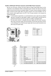
...used that can lead to an unstable or unbootable system. • The main power connector is turned off and all the components on the motherboard. Do not insert the power supply cable into pins under the protective cover when using a 2x12 power supply, remove the protective cover from ...the main power connector on the motherboard. 1/2) ATX_12V/ATX (2x2 12V Power Connector and 2x12 Main Power Connector) With the use of the power connector, the power supply can supply...
...used that can lead to an unstable or unbootable system. • The main power connector is turned off and all the components on the motherboard. Do not insert the power supply cable into pins under the protective cover when using a 2x12 power supply, remove the protective cover from ...the main power connector on the motherboard. 1/2) ATX_12V/ATX (2x2 12V Power Connector and 2x12 Main Power Connector) With the use of the power connector, the power supply can supply...

Manual
Page 23
The motherboard supports CPU fan speed control, which requires the use of floppy disk drives supported are not configuration jumper blocks. Overheating may hang. • These fan ... connect a floppy disk drive. The pin 1 of the cable is used to connect it is the ground wire). Hardware Installation 3/4) CPU_FAN/SYS_FAN (Fan Headers) The motherboard has a 4-pin CPU fan header (CPU_FAN) and a 3-pin (SYS_FAN) system fan headers. Definition 1 GND 2 +12V / Speed Control 3 Sense 4 Speed Control SYS_FAN: Pin No. 1 2 3 Definition GND...
The motherboard supports CPU fan speed control, which requires the use of floppy disk drives supported are not configuration jumper blocks. Overheating may hang. • These fan ... connect a floppy disk drive. The pin 1 of the cable is used to connect it is the ground wire). Hardware Installation 3/4) CPU_FAN/SYS_FAN (Fan Headers) The motherboard has a 4-pin CPU fan header (CPU_FAN) and a 3-pin (SYS_FAN) system fan headers. Definition 1 GND 2 +12V / Speed Control 3 Sense 4 Speed Control SYS_FAN: Pin No. 1 2 3 Definition GND...

Manual
Page 26
... activate AC'97 functionality via the audio software in Chapter 5, "Configuring 2/4/5.1/7.1-Channel Audio." • Audio signals will be present on each wire instead of the motherboard header. For HD Front Panel Audio: For AC'97 Front Panel Audio: 2 Pin No. Pin No. If you want to mute the back panel audio...
... activate AC'97 functionality via the audio software in Chapter 5, "Configuring 2/4/5.1/7.1-Channel Audio." • Audio signals will be present on each wire instead of the motherboard header. For HD Front Panel Audio: For AC'97 Front Panel Audio: 2 Pin No. Pin No. If you want to mute the back panel audio...
Manual
Page 28
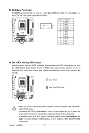
... - 28 - date information and BIOS configurations) and reset the CMOS values to clear the CMOS values (e.g. Failure to do so may cause damage to the motherboard. • After system restart, go to BIOS Setup to load factory defaults (select Load Optimized Defaults) or manually configure the BIOS settings (refer to remove...
... - 28 - date information and BIOS configurations) and reset the CMOS values to clear the CMOS values (e.g. Failure to do so may cause damage to the motherboard. • After system restart, go to BIOS Setup to load factory defaults (select Load Optimized Defaults) or manually configure the BIOS settings (refer to remove...


