
Manual
Page 1
GA-MA69GM-S2H AM2 socket motherboard for AMD AthlonTM 64 FX processor/ AMD AthlonTM 64 X2 Dual-Core processor/ AMD AthlonTM 64 processor/AMD SempronTM processor User's Manual Rev. 1001 12ME-MA69GMS2H-1001R * The WEEE marking on the product indicates this product must not be disposed of with user's other household waste and must be handed over to a designated collection point for the recycling of waste electrical and electronic equipment!! * The WEEE marking applies only in European Union's member states.
GA-MA69GM-S2H AM2 socket motherboard for AMD AthlonTM 64 FX processor/ AMD AthlonTM 64 X2 Dual-Core processor/ AMD AthlonTM 64 processor/AMD SempronTM processor User's Manual Rev. 1001 12ME-MA69GMS2H-1001R * The WEEE marking on the product indicates this product must not be disposed of with user's other household waste and must be handed over to a designated collection point for the recycling of waste electrical and electronic equipment!! * The WEEE marking applies only in European Union's member states.

Manual
Page 3
... owners. No part of documentations: „ For detailed product information, carefully read or download the information on/from the Support\Motherboard\Technology Guide page on how to use of this product, GIGABYTE provides the following types of this manual may be reproduced, copied, translated, transmitted, or published in this manual are legally...
... owners. No part of documentations: „ For detailed product information, carefully read or download the information on/from the Support\Motherboard\Technology Guide page on how to use of this product, GIGABYTE provides the following types of this manual may be reproduced, copied, translated, transmitted, or published in this manual are legally...

Manual
Page 4
Table of Contents OptionalItems ...6 Box Contents ...6 GA-MA69GM-S2H Motherboard Layout 7 Block Diagram ...8 Chapter 1 Hardware Installation 9 1-1 Installation Precautions 9 1-2 Product Specifications 10 1-3 Installing the CPU and CPU Cooler 13 1-3-1 Installing the CPU 13 1-3-2 Installing the CPU ...
Table of Contents OptionalItems ...6 Box Contents ...6 GA-MA69GM-S2H Motherboard Layout 7 Block Diagram ...8 Chapter 1 Hardware Installation 9 1-1 Installation Precautions 9 1-2 Product Specifications 10 1-3 Installing the CPU and CPU Cooler 13 1-3-1 Installing the CPU 13 1-3-2 Installing the CPU ...

Manual
Page 6
Box Contents GA-MA69GM-S2H motherboard Motherboard driver disk Motherboard driver disk (For Windows Vista) User's Manual One IDE cable and one floppy disk drive cable Two SATA 3Gb/s cables One TV Out bracket I/O Shield ...
Box Contents GA-MA69GM-S2H motherboard Motherboard driver disk Motherboard driver disk (For Windows Vista) User's Manual One IDE cable and one floppy disk drive cable Two SATA 3Gb/s cables One TV Out bracket I/O Shield ...

Manual
Page 7
GA-MA69GM-S2H Motherboard Layout KB_MS ATX_12V ATX Socket AM2 DVI-D VGA HDMI OPTICAL CPU_FAN 1394 USB CI TV LAN USB AUDIO F_AUDIO PCIE_4_1 AMD 690G LPT IDE FDD DDRII_1 DDRII_2 DDRII_3 DDRII_4 IT8716 PCIE_16 RTL 8110SC PCI1 CODEC PCI2 CD_IN GA-MA69GM-S2H AMD SB600 TSB43AB23 F_USB1 BIOS BATTERY CLR_CMOS COM F1_1394 F2_1394 F_USB2 F_USB3 SATAII2 SATAII0 SATAII3 SATAII1 SPDIF_IO SYS_FAN PWR_LED F_PANEL - 7 -
GA-MA69GM-S2H Motherboard Layout KB_MS ATX_12V ATX Socket AM2 DVI-D VGA HDMI OPTICAL CPU_FAN 1394 USB CI TV LAN USB AUDIO F_AUDIO PCIE_4_1 AMD 690G LPT IDE FDD DDRII_1 DDRII_2 DDRII_3 DDRII_4 IT8716 PCIE_16 RTL 8110SC PCI1 CODEC PCI2 CD_IN GA-MA69GM-S2H AMD SB600 TSB43AB23 F_USB1 BIOS BATTERY CLR_CMOS COM F1_1394 F2_1394 F_USB2 F_USB3 SATAII2 SATAII0 SATAII3 SATAII1 SPDIF_IO SYS_FAN PWR_LED F_PANEL - 7 -

Manual
Page 9
...high-temperature environment. • Turning on the power, make sure they are connected tightly and securely. • When handling the motherboard, avoid touching any installation steps or have a problem related to installation, do not have an ESD wrist strap, keep your ..., please verify that all cables and power connectors of electrostatic discharge (ESD). English Chapter 1 Hardware Installation 1-1 Installation Precautions The motherboard contains numerous delicate electronic circuits and components which can lead to damage to system components as well as physical harm to the user...
...high-temperature environment. • Turning on the power, make sure they are connected tightly and securely. • When handling the motherboard, avoid touching any installation steps or have a problem related to installation, do not have an ESD wrist strap, keep your ..., please verify that all cables and power connectors of electrostatic discharge (ESD). English Chapter 1 Hardware Installation 1-1 Installation Precautions The motherboard contains numerous delicate electronic circuits and components which can lead to damage to system components as well as physical harm to the user...

Manual
Page 10
...AMD AthlonTM 64 FX processor/AMD AthlonTM 64 X2 Dual-Core processor/ AMD AthlonTM 64 processor/AMD SempronTM processor (Go to GIGABYTE's website for the latest CPU support list.) Š 2000 MHz FSB Š North Bridge: AMD 690G Š South... (Note 1) Š Dual channel memory architecture Š Support for DDR2 800/667/533 MHz memory modules (Go to GIGABYTE's website for the latest memory support list.) Š Integrated in the South Bridge Š Up to 10 USB 2.0/1.1 ...to 2 IDE devices - 4 x SATA 3Gb/s connectors supporting up to the internal USB headers) GA-MA69GM-S2H Motherboard - 10 -
...AMD AthlonTM 64 FX processor/AMD AthlonTM 64 X2 Dual-Core processor/ AMD AthlonTM 64 processor/AMD SempronTM processor (Go to GIGABYTE's website for the latest CPU support list.) Š 2000 MHz FSB Š North Bridge: AMD 690G Š South... (Note 1) Š Dual channel memory architecture Š Support for DDR2 800/667/533 MHz memory modules (Go to GIGABYTE's website for the latest memory support list.) Š Integrated in the South Bridge Š Up to 10 USB 2.0/1.1 ...to 2 IDE devices - 4 x SATA 3Gb/s connectors supporting up to the internal USB headers) GA-MA69GM-S2H Motherboard - 10 -

Manual
Page 12
.... (Note 3) Whether the CPU fan speed control function is supported will depend on the CPU you install. (Note 4) Available functions in Easytune may differ by motherboard model. GA-MA69GM-S2H Motherboard - 12 -
.... (Note 3) Whether the CPU fan speed control function is supported will depend on the CPU you install. (Note 4) Available functions in Easytune may differ by motherboard model. GA-MA69GM-S2H Motherboard - 12 -

Manual
Page 13
... installing the CPU to your hardware specifications including the CPU, graphics card, memory, hard drive, etc. 1-3-1 Installing the CPU A. mended that the motherboard supports the CPU. (Go to GIGABYTE's website for the peripherals. The CPU cannot be set the frequency beyond hardware specifications since it does not meet the standard requirements for...
... installing the CPU to your hardware specifications including the CPU, graphics card, memory, hard drive, etc. 1-3-1 Installing the CPU A. mended that the motherboard supports the CPU. (Go to GIGABYTE's website for the peripherals. The CPU cannot be set the frequency beyond hardware specifications since it does not meet the standard requirements for...

Manual
Page 14
... the motherboard CPU socket. CPU Socket Locking Lever Step 1: Completely lift up the CPU socket locking lever. Adjust the CPU orientation if this occurs. Make sure that the CPU pins fit perfectly into the CPU socket. Do not force the CPU into their holes. Follow the steps below to the CPU. GA-MA69GM-S2H Motherboard...
... the motherboard CPU socket. CPU Socket Locking Lever Step 1: Completely lift up the CPU socket locking lever. Adjust the CPU orientation if this occurs. Make sure that the CPU pins fit perfectly into the CPU socket. Do not force the CPU into their holes. Follow the steps below to the CPU. GA-MA69GM-S2H Motherboard...

Manual
Page 15
...15 - English 1-3-2 Installing the CPU Cooler Follow the steps below to correctly install the CPU cooler on the CPU. (The following procedure uses the GIGABYTE cooler as the picture above shows) to lock into place. (Refer to your CPU cooler installation manual for instructions on installing the cooler.) Step ...5: Finally, attach the power connector of the CPU cooler to the CPU fan header (CPU_FAN) on the motherboard. Step 3: Hook the CPU cooler clip to the mounting lug on the surface of the installed CPU. Inadequately removing the CPU cooler may ...
...15 - English 1-3-2 Installing the CPU Cooler Follow the steps below to correctly install the CPU cooler on the CPU. (The following procedure uses the GIGABYTE cooler as the picture above shows) to lock into place. (Refer to your CPU cooler installation manual for instructions on installing the cooler.) Step ...5: Finally, attach the power connector of the CPU cooler to the CPU fan header (CPU_FAN) on the motherboard. Step 3: Hook the CPU cooler clip to the mounting lug on the surface of the installed CPU. Inadequately removing the CPU cooler may ...

Manual
Page 16
...two or four memory modules, it is recommended that memory of the memory. A memory module can be used . (Go to GIGABYTE's website for optimum performance. The four DDR2 memory sockets are divided into two channels and each channel has two memory sockets as ... DDRII_1, DDRII_3 Channel 1: DDRII_2, DDRII_4 Dual Channel Memory Configurations Table DDRII_1 DDRII_2 DDRII_3 DDRII_4 Two Modules DS/SS DS/SS - - - - - - - - GA-MA69GM-S2H Motherboard - 16 - If you begin to install the memory: • Make sure that memory of the same capacity, brand, speed, and chips be installed in Dual...
...two or four memory modules, it is recommended that memory of the memory. A memory module can be used . (Go to GIGABYTE's website for optimum performance. The four DDR2 memory sockets are divided into two channels and each channel has two memory sockets as ... DDRII_1, DDRII_3 Channel 1: DDRII_2, DDRII_4 Dual Channel Memory Configurations Table DDRII_1 DDRII_2 DDRII_3 DDRII_4 Two Modules DS/SS DS/SS - - - - - - - - GA-MA69GM-S2H Motherboard - 16 - If you begin to install the memory: • Make sure that memory of the same capacity, brand, speed, and chips be installed in Dual...

Manual
Page 17
... only fit in one direction. Place the memory module on the socket. Step 2: The clips at both ends of the memory, push down on this motherboard.
... only fit in one direction. Place the memory module on the socket. Step 2: The clips at both ends of the memory, push down on this motherboard.

Manual
Page 18
...Card: Pull out the small white- You can also press the latch on the card until it is fully seated in the expansion slot. 1. GA-MA69GM-S2H Motherboard - 18 - Remove the metal slot cover from the power outlet before you begin to install an expansion card: • Make sure the... motherboard supports the expansion card. Install the driver provided with your computer. English 1-5 Installing an Expansion Card Read the following guidelines before installing an ...
...Card: Pull out the small white- You can also press the latch on the card until it is fully seated in the expansion slot. 1. GA-MA69GM-S2H Motherboard - 18 - Remove the metal slot cover from the power outlet before you begin to install an expansion card: • Make sure the... motherboard supports the expansion card. Install the driver provided with your computer. English 1-5 Installing an Expansion Card Read the following guidelines before installing an ...

Manual
Page 20
...Optical S/PDIF Out Connector This connector provides digital audio out to an external audio system that your device and then remove it from the motherboard. • When removing the cable, pull it side to side to prevent an electrical short inside the cable connector. USB Port The ...to the instructions on setting up to connect front speakers in devices such as an USB keyboard/mouse, USB printer, USB flash drive and etc. GA-MA69GM-S2H Motherboard - 20 - Use this port for a headphone or 2-channel speaker. Use this audio jack for an IEEE 1394a device. Before using this feature...
...Optical S/PDIF Out Connector This connector provides digital audio out to an external audio system that your device and then remove it from the motherboard. • When removing the cable, pull it side to side to prevent an electrical short inside the cable connector. USB Port The ...to the instructions on setting up to connect front speakers in devices such as an USB keyboard/mouse, USB printer, USB flash drive and etc. GA-MA69GM-S2H Motherboard - 20 - Use this port for a headphone or 2-channel speaker. Use this audio jack for an IEEE 1394a device. Before using this feature...

Manual
Page 21
..., make sure your devices are compliant with the connectors you wish to connect. • Before installing the devices, be sure to the connector on the motherboard. - 21 -
..., make sure your devices are compliant with the connectors you wish to connect. • Before installing the devices, be sure to the connector on the motherboard. - 21 -

Manual
Page 22
... supply cable into pins under the protective cover when using a 2x12 power supply, remove the protective cover from the main power connector on the motherboard. If the 12V power connector is not connected, the computer will not start. • To meet expansion requirements, it is used (400W or...12V GND PS_ON(soft On/Off) GND GND GND -5V +5V +5V +5V (Only for 2x12-pin ATX) GND (Only for 2x12-pin ATX) GA-MA69GM-S2H Motherboard - 22 - The power connector possesses a foolproof design. Connect the power supply cable to an unstable or unbootable system. • The main power connector is...
... supply cable into pins under the protective cover when using a 2x12 power supply, remove the protective cover from the main power connector on the motherboard. If the 12V power connector is not connected, the computer will not start. • To meet expansion requirements, it is used (400W or...12V GND PS_ON(soft On/Off) GND GND GND -5V +5V +5V +5V (Only for 2x12-pin ATX) GND (Only for 2x12-pin ATX) GA-MA69GM-S2H Motherboard - 22 - The power connector possesses a foolproof design. Connect the power supply cable to an unstable or unbootable system. • The main power connector is...
Manual
Page 23
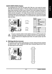
The black connector wire is recommended that a system fan be installed inside the chassis. The motherboard supports CPU fan speed control, which requires the use of floppy disk drives supported are designed with fan speed control design. CPU_FAN : Pin No. Overheating ... it is the ground wire. When connecting a fan cable, be sure to prevent your CPU and system from overheating. English 3/4) CPU_FAN/SYS_FAN (Fan Headers) The motherboard has a 4-pin CPU fan header (CPU_FAN) and a 3-pin system fan header (SYS_FAN). Most fans are : 360 KB, 720 KB, 1.2 MB, 1.44 MB, and 2.88 MB...
The black connector wire is recommended that a system fan be installed inside the chassis. The motherboard supports CPU fan speed control, which requires the use of floppy disk drives supported are designed with fan speed control design. CPU_FAN : Pin No. Overheating ... it is the ground wire. When connecting a fan cable, be sure to prevent your CPU and system from overheating. English 3/4) CPU_FAN/SYS_FAN (Fan Headers) The motherboard has a 4-pin CPU fan header (CPU_FAN) and a 3-pin system fan header (SYS_FAN). Most fans are : 360 KB, 720 KB, 1.2 MB, 1.44 MB, and 2.88 MB...

Manual
Page 24
... 6 RXP 7 GND • A RAID 0 or RAID 1 configuration requires at least four hard drives and the total number of hard drives must be an even number. GA-MA69GM-S2H Motherboard - 24 - If you wish to connect two IDE devices, remember to set the jumpers and the cabling according to the role of the IDE devices...
... 6 RXP 7 GND • A RAID 0 or RAID 1 configuration requires at least four hard drives and the total number of hard drives must be an even number. GA-MA69GM-S2H Motherboard - 24 - If you wish to connect two IDE devices, remember to set the jumpers and the cabling according to the role of the IDE devices...

Manual
Page 26
... Setup," for information about beep codes. • HD (IDE Hard Drive Activity LED) Connects to the hard drive activity LED on the chassis front panel. GA-MA69GM-S2H Motherboard - 26 - Refer to Chapter 5, "Troubleshooting," for more information). • SPEAK (Speaker): Connects to the speaker on the chassis front panel. The S0 On LED is...
... Setup," for information about beep codes. • HD (IDE Hard Drive Activity LED) Connects to the hard drive activity LED on the chassis front panel. GA-MA69GM-S2H Motherboard - 26 - Refer to Chapter 5, "Troubleshooting," for more information). • SPEAK (Speaker): Connects to the speaker on the chassis front panel. The S0 On LED is...


