
Manual
Page 4
...Contents ...6 GA-MA69GM-S2H Motherboard Layout 7 Block Diagram ...8 Chapter 1 Hardware Installation 9 1-1 Installation Precautions 9 1-2 Product Specifications 10 1-3 Installing the CPU and CPU Cooler 13 1-3-1 Installing the CPU 13 1-3-2 Installing the CPU Cooler 15 1-4 Installing the Memory 16 1-4-1 Dual Channel Memory Configuration 16 1-4-2 Installing a Memory 17 1-5 Installing an Expansion Card 18 1-6 Back Panel Connectors 19 1-7 Internal Connectors 21 Chapter 2 BIOS Setup 33 2-1 Startup Screen 34 2-2 The Main Menu 35 2-3 Standard CMOS Features 37 2-4 Advanced BIOS Features...
...Contents ...6 GA-MA69GM-S2H Motherboard Layout 7 Block Diagram ...8 Chapter 1 Hardware Installation 9 1-1 Installation Precautions 9 1-2 Product Specifications 10 1-3 Installing the CPU and CPU Cooler 13 1-3-1 Installing the CPU 13 1-3-2 Installing the CPU Cooler 15 1-4 Installing the Memory 16 1-4-1 Dual Channel Memory Configuration 16 1-4-2 Installing a Memory 17 1-5 Installing an Expansion Card 18 1-6 Back Panel Connectors 19 1-7 Internal Connectors 21 Chapter 2 BIOS Setup 33 2-1 Startup Screen 34 2-2 The Main Menu 35 2-3 Standard CMOS Features 37 2-4 Advanced BIOS Features...

Manual
Page 10
...; 1 x PCI Express x4 slot Š 2 x PCI slots Š South Bridge: - 1 x floppy disk drive connector supporting up to 1 floppy disk drive - 1 x IDE connector supporting ATA-133/100/66/33 and up to 2 IDE devices - 4 x SATA 3Gb/s connectors supporting up to the internal USB headers) GA-MA69GM-S2H Motherboard - 10 - TSB43AB23 chip Š Up to 3 IEEE 1394a ports (1 on the back panel, 6 via the IEEE 1394 bracket connected to the internal IEEE 1394 headers) Š Integrated in the North Bridge Š Realtek ALC889A codec Š High Definition Audio...
...; 1 x PCI Express x4 slot Š 2 x PCI slots Š South Bridge: - 1 x floppy disk drive connector supporting up to 1 floppy disk drive - 1 x IDE connector supporting ATA-133/100/66/33 and up to 2 IDE devices - 4 x SATA 3Gb/s connectors supporting up to the internal USB headers) GA-MA69GM-S2H Motherboard - 10 - TSB43AB23 chip Š Up to 3 IEEE 1394a ports (1 on the back panel, 6 via the IEEE 1394 bracket connected to the internal IEEE 1394 headers) Š Integrated in the North Bridge Š Realtek ALC889A codec Š High Definition Audio...

Manual
Page 16
... Dual Channel mode. 1. Dual Channel mode cannot be used and installed in the DDRII_1 and DDRII_2 sockets. Enabling Dual Channel memory mode will automatically detect the specifications and capacity of the memory. The four DDR2 memory sockets are unable to prevent hardware damage. • Memory modules have a foolproof design. GA-MA69GM-S2H Motherboard - 16 - If you install them in the same colored DDR2 sockets for the latest memory support list.) • Always turn off the computer and unplug the power...
... Dual Channel mode. 1. Dual Channel mode cannot be used and installed in the DDRII_1 and DDRII_2 sockets. Enabling Dual Channel memory mode will automatically detect the specifications and capacity of the memory. The four DDR2 memory sockets are unable to prevent hardware damage. • Memory modules have a foolproof design. GA-MA69GM-S2H Motherboard - 16 - If you install them in the same colored DDR2 sockets for the latest memory support list.) • Always turn off the computer and unplug the power...

Manual
Page 18
... 1-5 Installing an Expansion Card Read the following guidelines before installing an expansion card to prevent hardware damage. PCI Express x4 Slot PCI Express x16 Slot PCI Slot Follow the steps below to correctly install your expansion card(s). 7. If necessary, go to BIOS Setup to release the card. drawable bar at the end of the white-drawable bar to make any required BIOS changes for your expansion card in the expansion slot. 1. GA-MA69GM-S2H Motherboard...
... 1-5 Installing an Expansion Card Read the following guidelines before installing an expansion card to prevent hardware damage. PCI Express x4 Slot PCI Express x16 Slot PCI Slot Follow the steps below to correctly install your expansion card(s). 7. If necessary, go to BIOS Setup to release the card. drawable bar at the end of the white-drawable bar to make any required BIOS changes for your expansion card in the expansion slot. 1. GA-MA69GM-S2H Motherboard...
Manual
Page 23
... power connector wire indicates a positive connection and requires a +12V voltage. Do not place a jumper cap on the connector. 34 33 2 1 - 23 - The motherboard supports CPU fan speed control, which requires the use of floppy disk drives supported are not configuration jumper blocks. The types of a CPU fan with color-coded power connector wires. For optimum heat dissipation, it in damage to connect a floppy disk drive. Before connecting a floppy disk drive, locate the foolproof groove on the headers. 5) FDD (Floppy Disk Drive Connector) This connector is used...
... power connector wire indicates a positive connection and requires a +12V voltage. Do not place a jumper cap on the connector. 34 33 2 1 - 23 - The motherboard supports CPU fan speed control, which requires the use of floppy disk drives supported are not configuration jumper blocks. The types of a CPU fan with color-coded power connector wires. For optimum heat dissipation, it in damage to connect a floppy disk drive. Before connecting a floppy disk drive, locate the foolproof groove on the headers. 5) FDD (Floppy Disk Drive Connector) This connector is used...

Manual
Page 26
...chassis. The LED is on when the hard drive is operating. GA-MA69GM-S2H Motherboard - 26 - English 10) F_PANEL (Front Panel Header) Connect the power switch, reset switch, speaker and system status indicator on the chassis front panel to this header, make sure the wire assignments and the pin assignments are matched correctly. If a problem is detected, the BIOS may differ by issuing a beep code. A front panel module mainly consists of power switch, reset switch, power LED, hard drive activity LED, speaker and etc. Message/Power/ Power Sleep LED Switch Speaker Connector...
...chassis. The LED is on when the hard drive is operating. GA-MA69GM-S2H Motherboard - 26 - English 10) F_PANEL (Front Panel Header) Connect the power switch, reset switch, speaker and system status indicator on the chassis front panel to this header, make sure the wire assignments and the pin assignments are matched correctly. If a problem is detected, the BIOS may differ by issuing a beep code. A front panel module mainly consists of power switch, reset switch, power LED, hard drive activity LED, speaker and etc. Message/Power/ Power Sleep LED Switch Speaker Connector...

Manual
Page 31
... Installation Pin No. Definition 1 Signal 1 2 GND - 31 - To clear the CMOS values, place a jumper cap on the two pins to temporarily short the two pins or use a metal object like a screwdriver to remove the jumper cap from the power outlet before clearing the CMOS values. • After clearing the CMOS values and before turning on your computer, be sure to touch the two pins for BIOS configurations). 20) CI (Chassis Intrusion Header...
... Installation Pin No. Definition 1 Signal 1 2 GND - 31 - To clear the CMOS values, place a jumper cap on the two pins to temporarily short the two pins or use a metal object like a screwdriver to remove the jumper cap from the power outlet before clearing the CMOS values. • After clearing the CMOS values and before turning on your computer, be sure to touch the two pins for BIOS configurations). 20) CI (Chassis Intrusion Header...

Manual
Page 37
... hard drive access mode. is 13:0:0. English 2-3 Standard CMOS Features Date (mm:dd:yy) Time (hh:mm:ss) CMOS Setup Utility-Copyright (C) 1984-2007 Award Software Standard CMOS Features Thu, May 31 2007 22:31:24 Item Help Menu Level` ` IDE Channel 0 Master ` IDE Channel 0 Slave ` IDE Channel 2 Master ` IDE Channel 2 Slave ` IDE Channel 3 Master ` IDE Channel 3 Slave [None] [None] [None] [None] [None] [None] Drive A Floppy 3 Mode Support [1.44M, 3.5"] [Disabled] Halt On [All Errors] Base Memory Extended Memory 640K 239M KLJI: Move Enter...
... hard drive access mode. is 13:0:0. English 2-3 Standard CMOS Features Date (mm:dd:yy) Time (hh:mm:ss) CMOS Setup Utility-Copyright (C) 1984-2007 Award Software Standard CMOS Features Thu, May 31 2007 22:31:24 Item Help Menu Level` ` IDE Channel 0 Master ` IDE Channel 0 Slave ` IDE Channel 2 Master ` IDE Channel 2 Slave ` IDE Channel 3 Master ` IDE Channel 3 Slave [None] [None] [None] [None] [None] [None] Drive A Floppy 3 Mode Support [1.44M, 3.5"] [Disabled] Halt On [All Errors] Base Memory Extended Memory 640K 239M KLJI: Move Enter...

Manual
Page 39
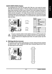
... list. Options are: Floppy, LS120, Hard Disk, CDROM, ZIP, USB-FDD, USB-ZIP, USB-CDROM, USB-HDD, Legacy LAN, Disabled. Capability Enables or disables the S.M.A.R.T. (Self Monitoring and Reporting Technology) capability of your system to report read/write errors of loading the operating system from the available devices. This feature allows your hard drive. BIOS Setup Capability Away Mode Init Display First x Surroundview Internal Graphics Mode Frame Buffer Size Current UMA Size [Auto] [Press Enter] [Floppy] [Hard Disk] [CDROM] [Setup] [Disabled] [Disabled] [PCI Slot] Disabled [Auto...
... list. Options are: Floppy, LS120, Hard Disk, CDROM, ZIP, USB-FDD, USB-ZIP, USB-CDROM, USB-HDD, Legacy LAN, Disabled. Capability Enables or disables the S.M.A.R.T. (Self Monitoring and Reporting Technology) capability of your system to report read/write errors of loading the operating system from the available devices. This feature allows your hard drive. BIOS Setup Capability Away Mode Init Display First x Surroundview Internal Graphics Mode Frame Buffer Size Current UMA Size [Auto] [Press Enter] [Floppy] [Hard Disk] [CDROM] [Setup] [Disabled] [Disabled] [PCI Slot] Disabled [Auto...
Manual
Page 40
PEG Sets the PCI Express graphics card on the PCIE_16 slot as the first display. Frame Buffer Size Frame buffer size is installed. Always outputs from the onboard VGA if no PCI Express VGA card is the total amount of the monitor display from the installed PCI graphics card, PCI Express graphics card, or the onboard VGA. Current UMA Size When Frame Buffer Size is installed. MS-DOS, for example, will use only this memory for the onboard graphics controller. GA-MA69GM-S2H Motherboard - 40 - Away Mode allows the system to Auto, this...
PEG Sets the PCI Express graphics card on the PCIE_16 slot as the first display. Frame Buffer Size Frame buffer size is installed. Always outputs from the onboard VGA if no PCI Express VGA card is the total amount of the monitor display from the installed PCI graphics card, PCI Express graphics card, or the onboard VGA. Current UMA Size When Frame Buffer Size is installed. MS-DOS, for example, will use only this memory for the onboard graphics controller. GA-MA69GM-S2H Motherboard - 40 - Away Mode allows the system to Auto, this...
Manual
Page 41
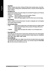
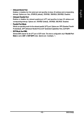
BIOS Setup English 2-5 Integrated Peripherals CMOS Setup Utility-Copyright (C) 1984-2007 Award Software Integrated Peripherals ` IDE Configuration OnChip SATA Controller OnChip SATA Type Onboard Audio Function Onboard 1394 Function Onboard LAN Function Onboard LAN Boot ROM OnChip USB Controller USB EHCI Controller USB Keyboard Support USB Mouse Support Legacy USB storage detect Onboard Serial Port Onboard Parallel Port Parallel Port Mode x ECP Mode Use DMA [Press Enter] [Enabled] [Native IDE] [Auto] [Enabled] [Enabled] [Disabled] [Enabled] [Enabled] [Enabled] [Disabled] [Enabled] [3F8/IRQ4...
BIOS Setup English 2-5 Integrated Peripherals CMOS Setup Utility-Copyright (C) 1984-2007 Award Software Integrated Peripherals ` IDE Configuration OnChip SATA Controller OnChip SATA Type Onboard Audio Function Onboard 1394 Function Onboard LAN Function Onboard LAN Boot ROM OnChip USB Controller USB EHCI Controller USB Keyboard Support USB Mouse Support Legacy USB storage detect Onboard Serial Port Onboard Parallel Port Parallel Port Mode x ECP Mode Use DMA [Press Enter] [Enabled] [Native IDE] [Auto] [Enabled] [Enabled] [Disabled] [Enabled] [Enabled] [Enabled] [Disabled] [Enabled] [3F8/IRQ4...

Manual
Page 42
... and hot plug. Advanced Host Controller Interface (AHCI) is an interface specification that do not support Native mode, e.g. RAID Enables RAID for the SATA controller. Windows 9X/ME SATA ->AHCI Configures the SATA controller to detect USB storage devices, including USB flash drives and USB hard drives during the POST. (Default: Enabled) GA-MA69GM-S2H Motherboard - 42 - Onboard LAN Boot ROM Allows you wish to install a 3rd party add-in network card instead of using the onboard audio, set this item to Disabled. In Legacy mode the SATA controller uses dedicated IRQs...
... and hot plug. Advanced Host Controller Interface (AHCI) is an interface specification that do not support Native mode, e.g. RAID Enables RAID for the SATA controller. Windows 9X/ME SATA ->AHCI Configures the SATA controller to detect USB storage devices, including USB flash drives and USB hard drives during the POST. (Default: Enabled) GA-MA69GM-S2H Motherboard - 42 - Onboard LAN Boot ROM Allows you wish to install a 3rd party add-in network card instead of using the onboard audio, set this item to Disabled. In Legacy mode the SATA controller uses dedicated IRQs...
Manual
Page 43
... Mode Use DMA Selects DMA channel for the onboard parallel (LPT) port. Options are : 378/IRQ7 (default), 278/IRQ5, 3BC/IRQ7, Disabled. Options are : 3 (default), 1. - 43 - Parallel Port Mode Selects an operating mode for the LPT port in ECP mode. This item is configurable only if Parallel Port Mode is set to ECP or ECP+EPP mode. BIOS Setup Options are : Auto, 2F8/IRQ3 (default), 3F8/IRQ4, 3E8/IRQ4, 2E8/IRQ3, Disabled. English Onboard Serial Port Enables or disables the first serial port...
... Mode Use DMA Selects DMA channel for the onboard parallel (LPT) port. Options are : 378/IRQ7 (default), 278/IRQ5, 3BC/IRQ7, Disabled. Options are : 3 (default), 1. - 43 - Parallel Port Mode Selects an operating mode for the LPT port in ECP mode. This item is configurable only if Parallel Port Mode is set to ECP or ECP+EPP mode. BIOS Setup Options are : Auto, 2F8/IRQ3 (default), 3F8/IRQ4, 3E8/IRQ4, 2E8/IRQ3, Disabled. English Onboard Serial Port Enables or disables the first serial port...

Manual
Page 44
... Event Wake Up HPET Support (Note) Power On By Mouse Power On By Keyboard x KB Power ON Password AC Back Function Power-On by Power button Configures the way to turn off the system. Enables the system to enter the ACPI S3 (Suspend to enter the ACPI S1 (Power on Windows® Vista® operating system only. In S3 sleep state, the system appears to be awakened from the installed USB device. (Default: Enabled) (Note) Supported...
... Event Wake Up HPET Support (Note) Power On By Mouse Power On By Keyboard x KB Power ON Password AC Back Function Power-On by Power button Configures the way to turn off the system. Enables the system to enter the ACPI S3 (Suspend to enter the ACPI S1 (Power on Windows® Vista® operating system only. In S3 sleep state, the system appears to be awakened from the installed USB device. (Default: Enabled) (Note) Supported...
Manual
Page 48
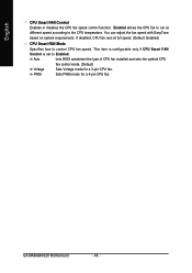
... CPU Smart FAN Control Enables or disables the CPU fan speed control function. Enabled allows the CPU fan to run at full speed. (Default: Enabled) CPU Smart FAN Mode Specifies how to control CPU fan speed. You can adjust the fan speed with EasyTune based on system requirements. Sets PWM mode for a 3-pin CPU fan. This item is configurable only if CPU Smart FAN Control is set to the CPU temperature. GA-MA69GM-S2H Motherboard - 48 - Auto Lets BIOS autodetect the type of CPU fan installed and sets the optimal CPU fan control mode. (Default) Voltage PWM Sets Voltage mode...
... CPU Smart FAN Control Enables or disables the CPU fan speed control function. Enabled allows the CPU fan to run at full speed. (Default: Enabled) CPU Smart FAN Mode Specifies how to control CPU fan speed. You can adjust the fan speed with EasyTune based on system requirements. Sets PWM mode for a 3-pin CPU fan. This item is configurable only if CPU Smart FAN Control is set to the CPU temperature. GA-MA69GM-S2H Motherboard - 48 - Auto Lets BIOS autodetect the type of CPU fan installed and sets the optimal CPU fan control mode. (Default) Voltage PWM Sets Voltage mode...
Manual
Page 69
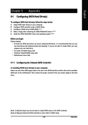
... that you do not want to create RAID array on the motherboard. Configure a RAID array in BIOS Setup. Then connect the power connector from your power supply to available SATA port on the SATA controller. (Note 2) Required when the SATA controller is set to AHCI or RAID mode. - 69 - B. Appendix English Chapter 5 Appendix 5-1 Configuring SATA Hard Drive(s) To configure SATA hard drive(s), follow the steps below: A. Configure SATA controller mode in RAID BIOS. (Note 1) D. C . Make a floppy disk containing the SATA RAID/AHCI driver. (Note 2) E. If you do not want to...
... that you do not want to create RAID array on the motherboard. Configure a RAID array in BIOS Setup. Then connect the power connector from your power supply to available SATA port on the SATA controller. (Note 2) Required when the SATA controller is set to AHCI or RAID mode. - 69 - B. Appendix English Chapter 5 Appendix 5-1 Configuring SATA Hard Drive(s) To configure SATA hard drive(s), follow the steps below: A. Configure SATA controller mode in RAID BIOS. (Note 1) D. C . Make a floppy disk containing the SATA RAID/AHCI driver. (Note 2) E. If you do not want to...
Manual
Page 77
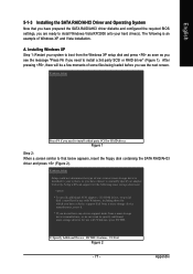
...-ROM drives, or special disk controllers for the following is an example of some files being loaded before you see the message "Press F6 if you have chosen to install a third party SCSI or RAID driver. Windows Setup Press F6 if you see the next screen. Windows Setup Setup could not determine the type of one or more mass storage devices installed in your system to boot from a mass storage device manufacturer...
...-ROM drives, or special disk controllers for the following is an example of some files being loaded before you see the message "Press F6 if you have chosen to install a third party SCSI or RAID driver. Windows Setup Press F6 if you see the next screen. Windows Setup Setup could not determine the type of one or more mass storage devices installed in your system to boot from a mass storage device manufacturer...

Manual
Page 82
... panel audio supports Intel HD Audio standard, you can listen to be simultaneously processed. The integrated HD (High Definition) audio provides Center/Subwoofer Speaker Out Rear Speaker Out Line In Front Speaker Out jack retasking capability that allows the user to the following instructions use Windows XP as the example operating system.) Step 1: After installing the audio driver, the Audio Manager icon will appear in jack and manually configure...
... panel audio supports Intel HD Audio standard, you can listen to be simultaneously processed. The integrated HD (High Definition) audio provides Center/Subwoofer Speaker Out Rear Speaker Out Line In Front Speaker Out jack retasking capability that allows the user to the following instructions use Windows XP as the example operating system.) Step 1: After installing the audio driver, the Audio Manager icon will appear in jack and manually configure...

Manual
Page 87
Digital PCM Output Setup: In the Audio Control Panel, click the Audio I/O tab. Enable this function to allow digital audio sources that are not digitally processed by DTS encoding to the Mic in jack (pink) on the front panel and back panel cannot be output from the S/PDIF OUT. 5-2-4 Configuring Microphone Recording Step 1: After installing the audio driver, the Audio Manager icon will appear in...
Digital PCM Output Setup: In the Audio Control Panel, click the Audio I/O tab. Enable this function to allow digital audio sources that are not digitally processed by DTS encoding to the Mic in jack (pink) on the front panel and back panel cannot be output from the S/PDIF OUT. 5-2-4 Configuring Microphone Recording Step 1: After installing the audio driver, the Audio Manager icon will appear in...
Manual
Page 95
... Award BIOS beep code descriptions may help you identify possible computer problems. (For reference only.) 1 short: System boots successfully 2 short: CMOS setting error 1 long, 1 short: Memory or motherboard error 1 long, 2 short: Monitor or graphics card error 1 long, 3 short: Keyboard error 1 long, 9 short: BIOS ROM error Continuous long beeps: Graphics card not inserted properly Continuous short beeps: Power error - 95 - A: If your motherboard has a clearing CMOS jumper, refer to the instructions on GIGABYTE's website. Press to show the advanced options. Saves changes and exit BIOS...
... Award BIOS beep code descriptions may help you identify possible computer problems. (For reference only.) 1 short: System boots successfully 2 short: CMOS setting error 1 long, 1 short: Memory or motherboard error 1 long, 2 short: Monitor or graphics card error 1 long, 3 short: Keyboard error 1 long, 9 short: BIOS ROM error Continuous long beeps: Graphics card not inserted properly Continuous short beeps: Power error - 95 - A: If your motherboard has a clearing CMOS jumper, refer to the instructions on GIGABYTE's website. Press to show the advanced options. Saves changes and exit BIOS...


