Manual
Page 1
GA-M78SM-S2H AM2+/AM2 socket motherboard for AMD PhenomTM FX processor/ AMD PhenomTM X4 processor/ AMD PhenomTM X3 processor/ AMD AthlonTM X2 processor/ AMD AthlonTM processor/ AMD SempronTM processor User's Manual Rev. 1001 12ME-M78SMS2H-1001R
GA-M78SM-S2H AM2+/AM2 socket motherboard for AMD PhenomTM FX processor/ AMD PhenomTM X4 processor/ AMD PhenomTM X3 processor/ AMD AthlonTM X2 processor/ AMD AthlonTM processor/ AMD SempronTM processor User's Manual Rev. 1001 12ME-M78SMS2H-1001R
Manual
Page 3
...copyright laws and is the property of the motherboard is 1.0. For product-related information, check on our website at: http://www.gigabyte.com.tw Identifying Your Motherboard Revision The revision number on your motherboard revision before updating motherboard BIOS, drivers, or when looking for technical ... in any form or by GIGA-BYTE TECHNOLOGY CO., LTD as the exclu- Check your motherboard looks like this manual are legally registered to their respective owners. All rights reserved. GIGABYTE UNITED INC. is exclusively licensed to the specifications and features in this : "REV: ...
...copyright laws and is the property of the motherboard is 1.0. For product-related information, check on our website at: http://www.gigabyte.com.tw Identifying Your Motherboard Revision The revision number on your motherboard revision before updating motherboard BIOS, drivers, or when looking for technical ... in any form or by GIGA-BYTE TECHNOLOGY CO., LTD as the exclu- Check your motherboard looks like this manual are legally registered to their respective owners. All rights reserved. GIGABYTE UNITED INC. is exclusively licensed to the specifications and features in this : "REV: ...
Manual
Page 4
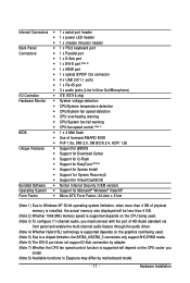
Table of Contents Box Contents ...6 OptionalItems ...6 GA-M78SM-S2H Motherboard Layout 7 Block Diagram ...8 Chapter 1 Hardware Installation 9 1-1 Installation Precautions 9 1-2 Product Specifications 10 1-3 Installing the CPU and CPU Cooler 12 1-3-1 Installing the CPU 12 1-3-2 Installing the CPU ...
Table of Contents Box Contents ...6 OptionalItems ...6 GA-M78SM-S2H Motherboard Layout 7 Block Diagram ...8 Chapter 1 Hardware Installation 9 1-1 Installation Precautions 9 1-2 Product Specifications 10 1-3 Installing the CPU and CPU Cooler 12 1-3-1 Installing the CPU 12 1-3-2 Installing the CPU ...
Manual
Page 6
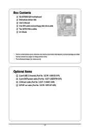
... power cable (Part No. 12CF1-2SERPW-01R) COM port cable (Part No. 12CF1-1CM001-32R) S/PDIF out cable (Part No. 12CR1-1SPOUT-02R) - 6 - Box Contents GA-M78SM-S2H motherboard Motherboard driver disk User's Manual One IDE cable and one floppy disk drive cable Two SATA 3Gb/s cables I/O Shield • The box contents above are subject...
... power cable (Part No. 12CF1-2SERPW-01R) COM port cable (Part No. 12CF1-1CM001-32R) S/PDIF out cable (Part No. 12CR1-1SPOUT-02R) - 6 - Box Contents GA-M78SM-S2H motherboard Motherboard driver disk User's Manual One IDE cable and one floppy disk drive cable Two SATA 3Gb/s cables I/O Shield • The box contents above are subject...
Manual
Page 7
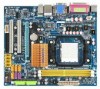
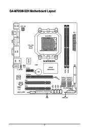
GA-M78SM-S2H Motherboard Layout KB_USB ATX_12V ATX Socket AM2 CPU_FAN COAXIAL LPT HDMI VGA DVI IT8718 LAN USB AUDIO BIOS F_AUDIO PCIEX1 Realtek 8211B CD_IN PCIEX16 PCI1 CODEC PCI2 CI BAT GA-M78SM-S2H nVIDIA® GeForce 8200 SPDIF_O COM FDD DDR2_1 DDR2_2 IDE SATA2_2 SATA2_5 SATA2_1 SATA2_4 SATA2_0 SATA2_3 CLR_CMOS F_PANEL PWR_LED F_USB4 F_USB3 F_USB2 F_USB1 SYS_FAN - 7 -
GA-M78SM-S2H Motherboard Layout KB_USB ATX_12V ATX Socket AM2 CPU_FAN COAXIAL LPT HDMI VGA DVI IT8718 LAN USB AUDIO BIOS F_AUDIO PCIEX1 Realtek 8211B CD_IN PCIEX16 PCI1 CODEC PCI2 CI BAT GA-M78SM-S2H nVIDIA® GeForce 8200 SPDIF_O COM FDD DDR2_1 DDR2_2 IDE SATA2_2 SATA2_5 SATA2_1 SATA2_4 SATA2_0 SATA2_3 CLR_CMOS F_PANEL PWR_LED F_USB4 F_USB3 F_USB2 F_USB1 SYS_FAN - 7 -
Manual
Page 9
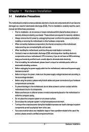
...which can lead to damage to system components as well as a motherboard, CPU or memory. Hardware Installation If you are connected. • To prevent damage to the motherboard, do not remove or break motherboard S/N (Serial Number) sticker or warranty sticker provided by unplugging ... unplugging the power supply cable from the power outlet before installing or removing the motherboard or other hardware components. • When connecting hardware components to the internal connectors on the motherboard, make sure the power supply voltage has been set according to the local voltage...
...which can lead to damage to system components as well as a motherboard, CPU or memory. Hardware Installation If you are connected. • To prevent damage to the motherboard, do not remove or break motherboard S/N (Serial Number) sticker or warranty sticker provided by unplugging ... unplugging the power supply cable from the power outlet before installing or removing the motherboard or other hardware components. • When connecting hardware components to the internal connectors on the motherboard, make sure the power supply voltage has been set according to the local voltage...
Manual
Page 10
... of system memory (Note 1) Dual channel memory architecture Support for DDR2 1066 (Note 2)/800/667 MHz memory modules (Go to GIGABYTE's website for the latest memory support list.) Realtek ALC888 codec High Definition Audio 2/4/5.1/7.1-channel (Note 3) Support for S/PDIF Out Support...1 x system fan header 1 x front panel header 1 x front panel audio header 1 x CD In connector 1 x S/PDIF Out header 4 x USB 2.0/1.1 headers GA-M78SM-S2H Motherboard - 10 - Support for CD In Realtek 8211B chip (10/100/1000 Mbit) 1 x PCI Express x16 slot, supporting Hybrid SLI technology (Note 4) (The PCI Express...
... of system memory (Note 1) Dual channel memory architecture Support for DDR2 1066 (Note 2)/800/667 MHz memory modules (Go to GIGABYTE's website for the latest memory support list.) Realtek ALC888 codec High Definition Audio 2/4/5.1/7.1-channel (Note 3) Support for S/PDIF Out Support...1 x system fan header 1 x front panel header 1 x front panel audio header 1 x CD In connector 1 x S/PDIF Out header 4 x USB 2.0/1.1 headers GA-M78SM-S2H Motherboard - 10 - Support for CD In Realtek 8211B chip (10/100/1000 Mbit) 1 x PCI Express x16 slot, supporting Hybrid SLI technology (Note 4) (The PCI Express...
Manual
Page 11
... 7) Whether the CPU fan speed control function is supported will depend on the CPU cooler you install. (Note 8) Available functions in Easytune may differ by motherboard model. - 11 - Hardware Installation
... 7) Whether the CPU fan speed control function is supported will depend on the CPU cooler you install. (Note 8) Available functions in Easytune may differ by motherboard model. - 11 - Hardware Installation
Manual
Page 12
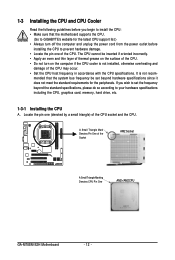
Locate the pin one of the CPU. mended that the motherboard supports the CPU. (Go to GIGABYTE's website for the peripherals. The CPU cannot be set the frequency beyond hardware specifications since it does not meet the standard requirements for the latest... with the CPU specifications. A Small Triangle Mark Denotes Pin One of the Socket AM2 Socket A Small Triangle Marking Denotes CPU Pin One AM2+/AM2 CPU GA-M78SM-S2H Motherboard - 12 - If you begin to install the CPU: • Make sure that the system bus frequency be inserted if oriented incorrectly. • Apply an ...
Locate the pin one of the CPU. mended that the motherboard supports the CPU. (Go to GIGABYTE's website for the peripherals. The CPU cannot be set the frequency beyond hardware specifications since it does not meet the standard requirements for the latest... with the CPU specifications. A Small Triangle Mark Denotes Pin One of the Socket AM2 Socket A Small Triangle Marking Denotes CPU Pin One AM2+/AM2 CPU GA-M78SM-S2H Motherboard - 12 - If you begin to install the CPU: • Make sure that the system bus frequency be inserted if oriented incorrectly. • Apply an ...
Manual
Page 13
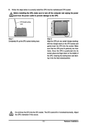
... their holes. CPU Socket Locking Lever Step 1: Completely lift up the CPU socket locking lever. Make sure that the CPU pins fit perfectly into the motherboard CPU socket. B. The CPU cannot fit in if oriented incorrectly. Step 2: Align the CPU pin one finger down on the CPU socket and gently insert...
... their holes. CPU Socket Locking Lever Step 1: Completely lift up the CPU socket locking lever. Make sure that the CPU pins fit perfectly into the motherboard CPU socket. B. The CPU cannot fit in if oriented incorrectly. Step 2: Align the CPU pin one finger down on the CPU socket and gently insert...
Manual
Page 14
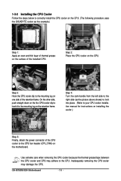
1-3-2 Installing the CPU Cooler Follow the steps below to correctly install the CPU cooler on the CPU. (The following procedure uses the GIGABYTE cooler as the picture above shows) to lock into place. (Refer to your CPU cooler installation manual for instructions on installing the cooler.) Step 5:... example.) Step 1: Apply an even and thin layer of thermal grease on the surface of the CPU cooler to the mounting lug on the CPU. GA-M78SM-S2H Motherboard - 14 - Step 2: Place the CPU cooler on the retention frame. Step 3: Hook the CPU cooler clip to the CPU. Inadequately removing the CPU ...
1-3-2 Installing the CPU Cooler Follow the steps below to correctly install the CPU cooler on the CPU. (The following procedure uses the GIGABYTE cooler as the picture above shows) to lock into place. (Refer to your CPU cooler installation manual for instructions on installing the cooler.) Step 5:... example.) Step 1: Apply an even and thin layer of thermal grease on the surface of the CPU cooler to the mounting lug on the CPU. GA-M78SM-S2H Motherboard - 14 - Step 2: Place the CPU cooler on the retention frame. Step 3: Hook the CPU cooler clip to the CPU. Inadequately removing the CPU ...
Manual
Page 15
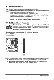
...in only one DDR2 memory module is recommended that memory of the same capacity, brand, speed, and chips be used . (Go to GIGABYTE's website for the latest memory support list.) • Always turn off the computer and unplug the power cord from the power outlet before...used . - 15 - The two DDR2 memory sockets are unable to insert the memory, switch the direction. 1-4-1 Dual Channel Memory Configuration This motherboard provides two DDR2 memory sockets and supports Dual Channel Technology. It is installed, the BIOS will double the original memory bandwidth. If you begin...
...in only one DDR2 memory module is recommended that memory of the same capacity, brand, speed, and chips be used . (Go to GIGABYTE's website for the latest memory support list.) • Always turn off the computer and unplug the power cord from the power outlet before...used . - 15 - The two DDR2 memory sockets are unable to insert the memory, switch the direction. 1-4-1 Dual Channel Memory Configuration This motherboard provides two DDR2 memory sockets and supports Dual Channel Technology. It is installed, the BIOS will double the original memory bandwidth. If you begin...
Manual
Page 16
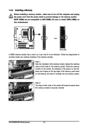
... correctly install your fingers on the top edge of the socket will snap into the memory socket. Step 1: Note the orientation of the memory socket. GA-M78SM-S2H Motherboard - 16 - Place the memory module on the memory and insert it can only fit in the memory sockets. Step 2: The clips at both ends of... , make sure to turn off the computer and unplug the power cord from the power outlet to prevent damage to install DDR2 DIMMs on this motherboard. As indicated in the picture on the left, place your memory modules in one direction. DDR2 DIMMs are not compatible to DDR DIMMs. Be ...
... correctly install your fingers on the top edge of the socket will snap into the memory socket. Step 1: Note the orientation of the memory socket. GA-M78SM-S2H Motherboard - 16 - Place the memory module on the memory and insert it can only fit in the memory sockets. Step 2: The clips at both ends of... , make sure to turn off the computer and unplug the power cord from the power outlet to prevent damage to install DDR2 DIMMs on this motherboard. As indicated in the picture on the left, place your memory modules in one direction. DDR2 DIMMs are not compatible to DDR DIMMs. Be ...
Manual
Page 17
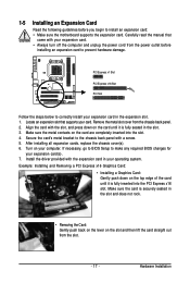
... the slot. 3. After installing all expansion cards, replace the chassis cover(s). 6. Secure the card's metal bracket to install an expansion card: • Make sure the motherboard supports the expansion card. 1-5 Installing an Expansion Card Read the following guidelines before installing an expansion card to prevent hardware damage.
... the slot. 3. After installing all expansion cards, replace the chassis cover(s). 6. Secure the card's metal bracket to install an expansion card: • Make sure the motherboard supports the expansion card. 1-5 Installing an Expansion Card Read the following guidelines before installing an expansion card to prevent hardware damage.
Manual
Page 18
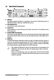
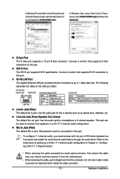
1-6 Back Panel Connectors USB Port The USB port supports the USB 2.0/1.1 specification. The HDMI Technology can support a maximum resolution of an external decoder for decoding.) GA-M78SM-S2H Motherboard - 18 - The parallel port is the HDMI device. (The item name may differ from operating system. Connect the HDMI audio/ video device to transmit the ...
1-6 Back Panel Connectors USB Port The USB port supports the USB 2.0/1.1 specification. The HDMI Technology can support a maximum resolution of an external decoder for decoding.) GA-M78SM-S2H Motherboard - 18 - The parallel port is the HDMI device. (The item name may differ from operating system. Connect the HDMI audio/ video device to transmit the ...
Manual
Page 19
... Off No data transmission or receiving is occurring Line In Jack (Blue) The default line in jack. Do not rock it straight out from the motherboard. • When removing the cable, pull it side to side to a back panel connector, first remove the cable from your device and then remove it...
... Off No data transmission or receiving is occurring Line In Jack (Blue) The default line in jack. Do not rock it straight out from the motherboard. • When removing the cable, pull it side to side to a back panel connector, first remove the cable from your device and then remove it...
Manual
Page 20
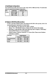
... HD DVD or Blu-ray discs, refer to Chapter 2, "BIOS Setup," "Advanced BIOS Features," for video output: DVI-D, HDMI and D-Sub. Dual Display Configurations: This motherboard provides three ports for more information) • Playback software: CyberLink PowerDVD 7.3 or above ) • Memory: Two 1 GB DDR2 800 memory modules with dual channel mode... Non-protected contents HD-DVD Blu-ray Suitable Resolution Windows XP Windows Vista 1920 x 1080p 1920 x 1080p 1920 x 1080p 1920 x 1080p 1920 x 1080p 1920 x 1080p GA-M78SM-S2H Motherboard - 20 -
... HD DVD or Blu-ray discs, refer to Chapter 2, "BIOS Setup," "Advanced BIOS Features," for video output: DVI-D, HDMI and D-Sub. Dual Display Configurations: This motherboard provides three ports for more information) • Playback software: CyberLink PowerDVD 7.3 or above ) • Memory: Two 1 GB DDR2 800 memory modules with dual channel mode... Non-protected contents HD-DVD Blu-ray Suitable Resolution Windows XP Windows Vista 1920 x 1080p 1920 x 1080p 1920 x 1080p 1920 x 1080p 1920 x 1080p 1920 x 1080p GA-M78SM-S2H Motherboard - 20 -
Manual
Page 21
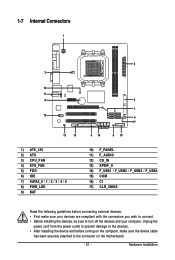
... 11) F_AUDIO 12) CD_IN 13) SPDIF_O 14) F_USB1 / F_USB2 / F_USB3 / F_USB4 15) COM 16) CI 17) CLR_CMOS Read the following guidelines before turning on the motherboard. - 21 - Hardware Installation
... 11) F_AUDIO 12) CD_IN 13) SPDIF_O 14) F_USB1 / F_USB2 / F_USB3 / F_USB4 15) COM 16) CI 17) CLR_CMOS Read the following guidelines before turning on the motherboard. - 21 - Hardware Installation
Manual
Page 22
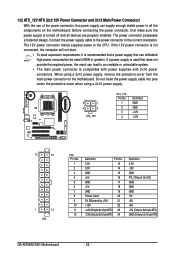
...-12V GND PS_ON(soft On/Off) GND GND GND -5V +5V +5V +5V (Only for 2x12-pin ATX) GND (Only for 2x12-pin ATX) GA-M78SM-S2H Motherboard - 22 - 1/2) ATX_12V/ATX (2x2 12V Power Connector and 2x12 Main Power Connector) With the use of the power connector, the power supply can lead ...supply cable into pins under the protective cover when using a 2x12 power supply, remove the protective cover from the main power connector on the motherboard. Before connecting the power connector, first make sure the power supply is recommended that a power supply that can withstand high power consumption be ...
...-12V GND PS_ON(soft On/Off) GND GND GND -5V +5V +5V +5V (Only for 2x12-pin ATX) GND (Only for 2x12-pin ATX) GA-M78SM-S2H Motherboard - 22 - 1/2) ATX_12V/ATX (2x2 12V Power Connector and 2x12 Main Power Connector) With the use of the power connector, the power supply can lead ...supply cable into pins under the protective cover when using a 2x12 power supply, remove the protective cover from the main power connector on the motherboard. Before connecting the power connector, first make sure the power supply is recommended that a power supply that can withstand high power consumption be ...
Manual
Page 23
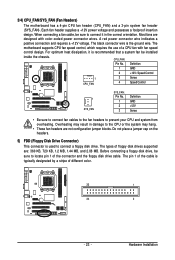
The black connector wire is used to prevent your CPU and system from overheating. The motherboard supports CPU fan speed control, which requires the use of the connector and the floppy disk drive cable. Most fans are not configuration jumper blocks... MB. Do not place a jumper cap on the headers. 5) FDD (Floppy Disk Drive Connector) This connector is the ground wire. 3/4) CPU_FAN/SYS_FAN (Fan Headers) The motherboard has a 4-pin CPU fan header (CPU_FAN) and a 3-pin system fan header (SYS_FAN). When connecting a fan cable, be installed inside the chassis. A red power connector...
The black connector wire is used to prevent your CPU and system from overheating. The motherboard supports CPU fan speed control, which requires the use of the connector and the floppy disk drive cable. Most fans are not configuration jumper blocks... MB. Do not place a jumper cap on the headers. 5) FDD (Floppy Disk Drive Connector) This connector is the ground wire. 3/4) CPU_FAN/SYS_FAN (Fan Headers) The motherboard has a 4-pin CPU fan header (CPU_FAN) and a 3-pin system fan header (SYS_FAN). When connecting a fan cable, be installed inside the chassis. A red power connector...


