
Manual
Page 3
... on/from the Support&Downloads\Motherboard\Technology Guide page on your motherboard revision before updating motherboard BIOS, drivers, or when looking for technical information. For example, "REV: 1.0" means the revision of this : "REV: X.X." All rights reserved. Check your motherboard looks like this manual may be reproduced, copied, translated, transmitted, or published in the use GIGABYTE's unique features, read the User's Manual. For instructions on how to...
... on/from the Support&Downloads\Motherboard\Technology Guide page on your motherboard revision before updating motherboard BIOS, drivers, or when looking for technical information. For example, "REV: 1.0" means the revision of this : "REV: X.X." All rights reserved. Check your motherboard looks like this manual may be reproduced, copied, translated, transmitted, or published in the use GIGABYTE's unique features, read the User's Manual. For instructions on how to...
Manual
Page 4
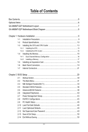
... Box Contents...6 Optional Items...6 GA-M68MT-S2P Motherboard Layout 7 GA-M68MT-S2P Motherboard Block Diagram 8 Chapter 1 Hardware Installation 9 1-1 Installation Precautions 9 1-2 Product Specifications 10 1-3 Installing the CPU and CPU Cooler 13 1-3-1 Installing the CPU 13 1-3-2 Installing the CPU Cooler 15 1-4 Installing the Memory 16 1-4-1 Dual Channel Memory Configuration 16 1-4-2 Installing a Memory 17 1-5 Installing an Expansion Card 18 1-6 Back Panel Connectors 19 1-7 Internal Connectors 21 Chapter 2 BIOS Setup 29 2-1 Startup Screen 30 2-2 The Main Menu 31 2-3 MB...
... Box Contents...6 Optional Items...6 GA-M68MT-S2P Motherboard Layout 7 GA-M68MT-S2P Motherboard Block Diagram 8 Chapter 1 Hardware Installation 9 1-1 Installation Precautions 9 1-2 Product Specifications 10 1-3 Installing the CPU and CPU Cooler 13 1-3-1 Installing the CPU 13 1-3-2 Installing the CPU Cooler 15 1-4 Installing the Memory 16 1-4-1 Dual Channel Memory Configuration 16 1-4-2 Installing a Memory 17 1-5 Installing an Expansion Card 18 1-6 Back Panel Connectors 19 1-7 Internal Connectors 21 Chapter 2 BIOS Setup 29 2-1 Startup Screen 30 2-2 The Main Menu 31 2-3 MB...
Manual
Page 5
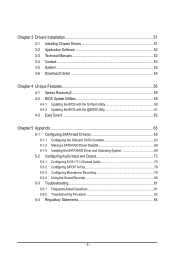
... Xpress Recovery2 55 4-2 BIOS Update Utilities 58 4-2-1 Updating the BIOS with the Q-Flash Utility 58 4-2-2 Updating the BIOS with the @BIOS Utility 61 4-3 EasyTune 6...62 Chapter 5 Appendix...63 5-1 Configuring SATA Hard Drive(s 63 5-1-1 Configuring the Onboard SATA Controller 63 5-1-2 Making a SATA RAID Driver Diskette 68 5-1-3 Installing the SATA RAID Driver and Operating System 69 5-2 Configuring Audio Input and Output 73 5-2-1 Configuring 2/4/5.1/7.1-Channel Audio 73 5-2-2 Configuring S/PDIF In/Out 76 5-2-3 Configuring Microphone Recording 78 5-2-4 Using the Sound Recorder 80...
... Xpress Recovery2 55 4-2 BIOS Update Utilities 58 4-2-1 Updating the BIOS with the Q-Flash Utility 58 4-2-2 Updating the BIOS with the @BIOS Utility 61 4-3 EasyTune 6...62 Chapter 5 Appendix...63 5-1 Configuring SATA Hard Drive(s 63 5-1-1 Configuring the Onboard SATA Controller 63 5-1-2 Making a SATA RAID Driver Diskette 68 5-1-3 Installing the SATA RAID Driver and Operating System 69 5-2 Configuring Audio Input and Output 73 5-2-1 Configuring 2/4/5.1/7.1-Channel Audio 73 5-2-2 Configuring S/PDIF In/Out 76 5-2-3 Configuring Microphone Recording 78 5-2-4 Using the Sound Recorder 80...
Manual
Page 6
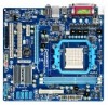
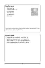
The box contents are for reference only. Optional Items Floppy disk drive cable (Part No. 12CF1-1FD001-7*R) 2-port USB 2.0 bracket (Part No. 12CR1-1UB030-5*R) 2-port SATA power cable (Part No. 12CF1-2SERPW-0*R) S/PDIF In and Out cable (Part No. 12CR1-1SPINO-1*R) - 6 - Box Contents GA-M68MT-S2P Motherboard driver disk User's Manual One IDE cable One SATA cable I/O Shield • The box contents above are subject to change without notice. • The motherboard image is for reference only and the actual items shall depend on the product package you obtain.
The box contents are for reference only. Optional Items Floppy disk drive cable (Part No. 12CF1-1FD001-7*R) 2-port USB 2.0 bracket (Part No. 12CR1-1UB030-5*R) 2-port SATA power cable (Part No. 12CF1-2SERPW-0*R) S/PDIF In and Out cable (Part No. 12CR1-1SPINO-1*R) - 6 - Box Contents GA-M68MT-S2P Motherboard driver disk User's Manual One IDE cable One SATA cable I/O Shield • The box contents above are subject to change without notice. • The motherboard image is for reference only and the actual items shall depend on the product package you obtain.
Manual
Page 10
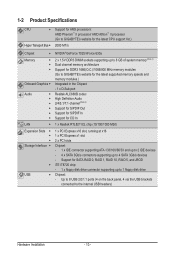
...1066/800 MHz memory modules (Go to GIGABYTE's website for the latest supported memory speeds and memory modules.) Integrated in the Chipset: - 1 x D-Sub port Realtek ALC888B codec High Definition Audio 2/4/5.1/7.1-channel (Note 2) Support for S/PDIF Out Support for S/PDIF In Support for SATA RAID 0, RAID 1, RAID 10, RAID 5, and JBOD iTE IT8720 chip: - 1 x floppy disk drive connector supporting up to 4 SATA 3Gb/s devices - Up to 8 USB 2.0/1.1 ports (4 on the back panel, 4 via the USB brackets connected to the internal USB headers) Hardware Installation - 10...
...1066/800 MHz memory modules (Go to GIGABYTE's website for the latest supported memory speeds and memory modules.) Integrated in the Chipset: - 1 x D-Sub port Realtek ALC888B codec High Definition Audio 2/4/5.1/7.1-channel (Note 2) Support for S/PDIF Out Support for S/PDIF In Support for SATA RAID 0, RAID 1, RAID 10, RAID 5, and JBOD iTE IT8720 chip: - 1 x floppy disk drive connector supporting up to 4 SATA 3Gb/s devices - Up to 8 USB 2.0/1.1 ports (4 on the back panel, 4 via the USB brackets connected to the internal USB headers) Hardware Installation - 10...
Manual
Page 18
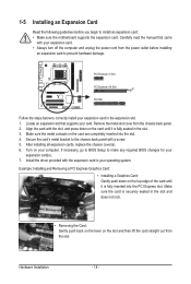
... PCI Express slot. Carefully read the manual that supports your operating system. Locate an expansion slot that came with a screw. 5. Align the card with the expansion card in the expansion slot. 1. Secure the card's metal bracket to correctly install your computer. After installing all expansion cards, replace the chassis cover(s). 6. PCI Express x1 Slot PCI Express x16 Slot PCI Slot Follow the steps below to the chassis back panel with your expansion card(s). 7. Example: Installing and Removing a PCI Express Graphics Card: • Installing a Graphics Card...
... PCI Express slot. Carefully read the manual that supports your operating system. Locate an expansion slot that came with a screw. 5. Align the card with the expansion card in the expansion slot. 1. Secure the card's metal bracket to correctly install your computer. After installing all expansion cards, replace the chassis cover(s). 6. PCI Express x1 Slot PCI Express x16 Slot PCI Slot Follow the steps below to the chassis back panel with your expansion card(s). 7. Example: Installing and Removing a PCI Express Graphics Card: • Installing a Graphics Card...

Manual
Page 28
... cause damage to the motherboard. • After system restart, go to BIOS Setup to load factory defaults (select Load Optimized Defaults) or manually configure the BIOS settings (refer to Chapter 2, "BIOS Setup," for a few seconds. Hardware Installation - 28 - date information and BIOS configurations) and reset the CMOS values to touch the two pins for BIOS configurations). 14) BAT (Battery) The battery provides power to clear the CMOS values (e.g. To clear the CMOS values, place a jumper cap on your computer...
... cause damage to the motherboard. • After system restart, go to BIOS Setup to load factory defaults (select Load Optimized Defaults) or manually configure the BIOS settings (refer to Chapter 2, "BIOS Setup," for a few seconds. Hardware Installation - 28 - date information and BIOS configurations) and reset the CMOS values to touch the two pins for BIOS configurations). 14) BAT (Battery) The battery provides power to clear the CMOS values (e.g. To clear the CMOS values, place a jumper cap on your computer...
Manual
Page 29
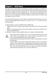
..., try to clear the CMOS values and reset the board to default values. (Refer to the "Load Optimized Defaults" section in this chapter or introductions of the battery/ clearing CMOS jumper in Chapter 1 for the beep codes description. • It is recommended that searches and downloads the latest version of BIOS from the Internet and updates the BIOS. When the power is a Windows-based utility that you not alter the default settings (unless...
..., try to clear the CMOS values and reset the board to default values. (Refer to the "Load Optimized Defaults" section in this chapter or introductions of the battery/ clearing CMOS jumper in Chapter 1 for the beep codes description. • It is recommended that searches and downloads the latest version of BIOS from the Internet and updates the BIOS. When the power is a Windows-based utility that you not alter the default settings (unless...
Manual
Page 32
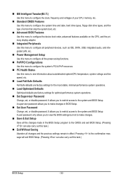
... clock, frequency and voltages of your CPU, memory, etc. Standard CMOS Features Use this menu to configure the system time and date, hard drive types, floppy disk drive types, and the type of errors that stop the system boot, etc. Advanced BIOS Features Use this menu to configure the device boot order, advanced features available on the CPU, and the primary display adapter. Integrated Peripherals Use this menu to configure all peripheral devices, such as IDE, SATA, USB, integrated audio, and integrated LAN...
... clock, frequency and voltages of your CPU, memory, etc. Standard CMOS Features Use this menu to configure the system time and date, hard drive types, floppy disk drive types, and the type of errors that stop the system boot, etc. Advanced BIOS Features Use this menu to configure the device boot order, advanced features available on the CPU, and the primary display adapter. Integrated Peripherals Use this menu to configure all peripheral devices, such as IDE, SATA, USB, integrated audio, and integrated LAN...

Manual
Page 33
... Tweaker(M.I.T.) CMOS Setup Utility-Copyright (C) 1984-2009 Award Software MB Intelligent Tweaker(M.I.T.) Set Memory Clock x Memory Clock } DRAM Configuration CPU NB VID Control CPU Voltage Control DDR3 Voltage Control Normal CPU Vcore [Auto] x5.33 1066Mhz [Press Enter] [Normal] [Normal] [Auto] 1.3500V Item Help Menu Level Move Enter: Select F5: Previous Values +/-/PU/PD: Value F10: Save F6: Fail-Safe Defaults ESC: Exit F1: General Help F7: Optimized Defaults Whether the system will work stably with the overclock settings you...
... Tweaker(M.I.T.) CMOS Setup Utility-Copyright (C) 1984-2009 Award Software MB Intelligent Tweaker(M.I.T.) Set Memory Clock x Memory Clock } DRAM Configuration CPU NB VID Control CPU Voltage Control DDR3 Voltage Control Normal CPU Vcore [Auto] x5.33 1066Mhz [Press Enter] [Normal] [Normal] [Auto] 1.3500V Item Help Menu Level Move Enter: Select F5: Previous Values +/-/PU/PD: Value F10: Save F6: Fail-Safe Defaults ESC: Exit F1: General Help F7: Optimized Defaults Whether the system will work stably with the overclock settings you...

Manual
Page 35
... pin is from +0.05V to your CPU or reduce the useful life of the CPU. DDR3 Voltage Control Allows you to set the memory to power down mode. CKE Power Down Mode Determines whether to set the memory voltage. CPU Voltage Control Allows you to set the CPU Northbridge VID voltage. Normal Supplies the memory voltage as required. BIOS Setup Precharge Time Options are : Auto (default), 4T~7T. Options are : Auto (default), 11T~42T. The adjustable range is dependent on the CPU being installed. (Default...
... pin is from +0.05V to your CPU or reduce the useful life of the CPU. DDR3 Voltage Control Allows you to set the memory to power down mode. CKE Power Down Mode Determines whether to set the memory voltage. CPU Voltage Control Allows you to set the CPU Northbridge VID voltage. Normal Supplies the memory voltage as required. BIOS Setup Precharge Time Options are : Auto (default), 4T~7T. Options are : Auto (default), 11T~42T. The adjustable range is dependent on the CPU being installed. (Default...
Manual
Page 38
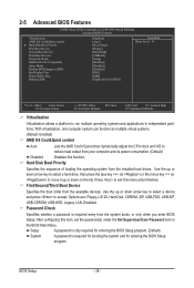
Options are: Floppy, LS120, Hard Disk, CDROM, ZIP, USB-FDD, USB-ZIP, USB-CDROM, USB-HDD, Legacy LAN, Disabled. BIOS Setup - 38 - After configuring this menu when finished. Setup A password is only required for entering the BIOS Setup program. (Default) System A password is required every time the system boots, or only when you enter BIOS Setup. With virtualization, one computer system can function as multiple virtual systems. (Default: Enabled) AMD K8 Cool&Quiet control Auto Lets the AMD Cool'n'Quiet driver dynamically adjust the CPU clock and VID to...
Options are: Floppy, LS120, Hard Disk, CDROM, ZIP, USB-FDD, USB-ZIP, USB-CDROM, USB-HDD, Legacy LAN, Disabled. BIOS Setup - 38 - After configuring this menu when finished. Setup A password is only required for entering the BIOS Setup program. (Default) System A password is required every time the system boots, or only when you enter BIOS Setup. With virtualization, one computer system can function as multiple virtual systems. (Default: Enabled) AMD K8 Cool&Quiet control Auto Lets the AMD Cool'n'Quiet driver dynamically adjust the CPU clock and VID to...
Manual
Page 39
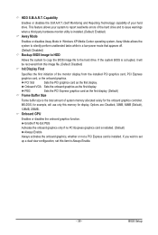
... hard drive and to issue warnings when a third party hardware monitor utility is corrupted, it will use only this item to the hard drive. HDD S.M.A.R.T. Capability Enables or disables the S.M.A.R.T. (Self Monitoring and Reporting Technology) capability of your system to report read/write errors of system memory allocated solely for display. PCI Slot Sets the PCI graphics card as the first display. If you wish to set up a dual view configuration, set this memory for the onboard graphics controller. Away Mode...
... hard drive and to issue warnings when a third party hardware monitor utility is corrupted, it will use only this item to the hard drive. HDD S.M.A.R.T. Capability Enables or disables the S.M.A.R.T. (Self Monitoring and Reporting Technology) capability of your system to report read/write errors of system memory allocated solely for display. PCI Slot Sets the PCI graphics card as the first display. If you wish to set up a dual view configuration, set this memory for the onboard graphics controller. Away Mode...

Manual
Page 40
.... (Default: Enabled) USB Memory Type Specifies the type of memory allocated for the integrated SATA 3Gb/s controllers. 2-6 Integrated Peripherals CMOS Setup Utility-Copyright (C) 1984-2009 Award Software Integrated Peripherals On-Chip IDE Channel NV Serial-ATA Controller IDE Prefetch Mode USB Memory Type } Serial-ATA RAID Config Onboard Audio Function On-Chip MAC Lan Onboard LAN Boot ROM Onboard Serial Port 1 Onboard Parallel Port Parallel Port Mode x ECP Mode Use DMA On-Chip USB USB Keyboard Support USB Mouse Support Legacy USB storage detect...
.... (Default: Enabled) USB Memory Type Specifies the type of memory allocated for the integrated SATA 3Gb/s controllers. 2-6 Integrated Peripherals CMOS Setup Utility-Copyright (C) 1984-2009 Award Software Integrated Peripherals On-Chip IDE Channel NV Serial-ATA Controller IDE Prefetch Mode USB Memory Type } Serial-ATA RAID Config Onboard Audio Function On-Chip MAC Lan Onboard LAN Boot ROM Onboard Serial Port 1 Onboard Parallel Port Parallel Port Mode x ECP Mode Use DMA On-Chip USB USB Keyboard Support USB Mouse Support Legacy USB storage detect...

Manual
Page 41
... to Disabled. Onboard LAN Boot ROM Allows you wish to install a 3rd party add-in ECP mode. ECP Mode Use DMA Selects DMA channel for the LPT port in network card instead of the second integrated SATA 3Gb/s controller. This item is configurable only if the NV SATA RAID function item is set to Enabled. (Default: Enabled) NV SATA 2 Secondary RAID Enables or disables RAID for the onboard parallel (LPT) port. On-Chip USB V1.1+V2.0 V1.1 Disabled Enables the USB 1.1 and USB 2.0 controllers. (Default) Enables only the USB 1.1 controller. Options...
... to Disabled. Onboard LAN Boot ROM Allows you wish to install a 3rd party add-in ECP mode. ECP Mode Use DMA Selects DMA channel for the LPT port in network card instead of the second integrated SATA 3Gb/s controller. This item is configurable only if the NV SATA RAID function item is set to Enabled. (Default: Enabled) NV SATA 2 Secondary RAID Enables or disables RAID for the onboard parallel (LPT) port. On-Chip USB V1.1+V2.0 V1.1 Disabled Enables the USB 1.1 and USB 2.0 controllers. (Default) Enables only the USB 1.1 controller. Options...
Manual
Page 43
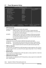
... a PCI or PCIe device. Instant-Off Press the power button and then the system will enter suspend mode. PME Event Wake Up Allows the system to be turned off instantly. (Default) Delay 4 Sec. BIOS Setup Soft-Off by Power button Configures the way to be awakened from ACPI S3 sleep state by a wake-up signal from the installed USB device. (Default: Enabled) (Note) Supported on Suspend) sleep state. Note: To use this function, you need an ATX power supply...
... a PCI or PCIe device. Instant-Off Press the power button and then the system will enter suspend mode. PME Event Wake Up Allows the system to be turned off instantly. (Default) Delay 4 Sec. BIOS Setup Soft-Off by Power button Configures the way to be awakened from ACPI S3 sleep state by a wake-up signal from the installed USB device. (Default: Enabled) (Note) Supported on Suspend) sleep state. Note: To use this function, you need an ATX power supply...
Manual
Page 63
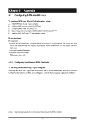
... SATA port on the SATA controller. - 63 - Then connect the power connector from your power supply to the hard drive. (Note) Skip this step if you do not want to create RAID, you do not want to create RAID array on the motherboard. Install the SATA RAID driver (Note) and operating system. Appendix C. Before you use two hard drives with identical model and capacity). Configure SATA controller mode in RAID BIOS. (Note) D. Make a floppy disk containing the SATA RAID driver for Windows XP. (Note) E. Installing SATA hard drive...
... SATA port on the SATA controller. - 63 - Then connect the power connector from your power supply to the hard drive. (Note) Skip this step if you do not want to create RAID, you do not want to create RAID array on the motherboard. Install the SATA RAID driver (Note) and operating system. Appendix C. Before you use two hard drives with identical model and capacity). Configure SATA controller mode in RAID BIOS. (Note) D. Make a floppy disk containing the SATA RAID driver for Windows XP. (Note) E. Installing SATA hard drive...

Manual
Page 68
... motherboard driver disk to install the SATA controller driver during the Windows setup process. For installing Windows Vista, you need to a floppy disk. Refer to be recognized during the OS installation. Press any key to copy the RAID driver for your optical drive folder, double click the Menu.exe file in Figure 3. 3: Insert the blank formatted disk. 5-1-2 Making a SATA RAID Driver Diskette To successfully install operating system onto RAID drive(s), you also can copy the SATA controller driver from the menu...
... motherboard driver disk to install the SATA controller driver during the Windows setup process. For installing Windows Vista, you need to a floppy disk. Refer to be recognized during the OS installation. Press any key to copy the RAID driver for your optical drive folder, double click the Menu.exe file in Figure 3. 3: Insert the blank formatted disk. 5-1-2 Making a SATA RAID Driver Diskette To successfully install operating system onto RAID drive(s), you also can copy the SATA controller driver from the menu...
Manual
Page 69
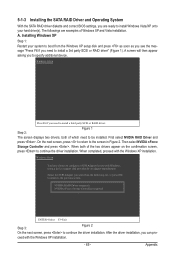
... need to the previous screen. NVIDIA RAID Driver (required) NVIDIA nForce Storage Controller (required) ENTER=Select F3=Exit Step 3: Figure 2 On the next screen, press to specify additional device. A screen will then appear asking you to continue the driver installation. Step 2: Figure 1 The screen displays two drivers, both of the two drivers appear on the confirmation screen, press to configure a SCSI Adapter for use with Windows, using a device support disk provided by an...
... need to the previous screen. NVIDIA RAID Driver (required) NVIDIA nForce Storage Controller (required) ENTER=Select F3=Exit Step 3: Figure 2 On the next screen, press to specify additional device. A screen will then appear asking you to continue the driver installation. Step 2: Figure 1 The screen displays two drivers, both of the two drivers appear on the confirmation screen, press to configure a SCSI Adapter for use with Windows, using a device support disk provided by an...
Manual
Page 81
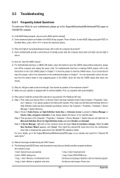
... 1 long, 3 short: Keyboard error 2 short: CMOS setting error 1 long, 9 short: BIOS ROM error 1 long, 1 short: Memory or motherboard error Continuous long beeps: Graphics card not inserted properly 1 long, 2 short: Monitor or graphics card error Continuous short beeps: Power error - 81 - Press to clear the CMOS values. If yes, please disable this device. (If not, skip this jumper, refer to the maximum volume? Then install the onboard HD audio driver from the motherboard driver disk or download the audio driver from GIGABYTE's website to show the advanced options...
... 1 long, 3 short: Keyboard error 2 short: CMOS setting error 1 long, 9 short: BIOS ROM error 1 long, 1 short: Memory or motherboard error Continuous long beeps: Graphics card not inserted properly 1 long, 2 short: Monitor or graphics card error Continuous short beeps: Power error - 81 - Press to clear the CMOS values. If yes, please disable this device. (If not, skip this jumper, refer to the maximum volume? Then install the onboard HD audio driver from the motherboard driver disk or download the audio driver from GIGABYTE's website to show the advanced options...


