Manual
Page 4
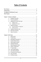
......6 Optional Items...6 GA-M68M-S2P Motherboard Layout 7 Block Diagram...8 Chapter 1 Hardware Installation 9 1-1 Installation Precautions 9 1-2 Product Specifications 10 1-3 Installing the CPU and CPU Cooler 13 1-3-1 Installing the CPU 13 1-3-2 Installing the CPU Cooler 15 1-4 Installing the Memory 16 1-4-1 Dual Channel Memory Configuration 16 1-4-2 Installing a Memory 17 1-5 Installing an Expansion Card 18 1-6 Back Panel Connectors 19...
......6 Optional Items...6 GA-M68M-S2P Motherboard Layout 7 Block Diagram...8 Chapter 1 Hardware Installation 9 1-1 Installation Precautions 9 1-2 Product Specifications 10 1-3 Installing the CPU and CPU Cooler 13 1-3-1 Installing the CPU 13 1-3-2 Installing the CPU Cooler 15 1-4 Installing the Memory 16 1-4-1 Dual Channel Memory Configuration 16 1-4-2 Installing a Memory 17 1-5 Installing an Expansion Card 18 1-6 Back Panel Connectors 19...
Manual
Page 10
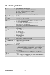
... Phenom™ II processor/ AMD Phenom™ processor/ AMD Athlon™ II processor/ AMD Athlon™ processor/ AMD Sempron™ processor (Go to GIGABYTE's website for the latest CPU support list.) 2000 MT/s Chipset NVIDIA® GeForce 7025/nForce 630a Memory Onboard Graphics Audio ...: - 1 x floppy disk drive connector supporting up to 1 floppy disk drive USB Chipset - Up to 8 USB 2.0/1.1 ports (4 on the back panel, 4 via the USB brackets connected to the internal USB headers) Hardware Installation - 10 -
... Phenom™ II processor/ AMD Phenom™ processor/ AMD Athlon™ II processor/ AMD Athlon™ processor/ AMD Sempron™ processor (Go to GIGABYTE's website for the latest CPU support list.) 2000 MT/s Chipset NVIDIA® GeForce 7025/nForce 630a Memory Onboard Graphics Audio ...: - 1 x floppy disk drive connector supporting up to 1 floppy disk drive USB Chipset - Up to 8 USB 2.0/1.1 ports (4 on the back panel, 4 via the USB brackets connected to the internal USB headers) Hardware Installation - 10 -

Manual
Page 11
... main power connector w 1 x 4-pin ATX 12V power connector w 1 x floppy disk drive connector w 1 x IDE connector w 4 x SATA 3Gb/s connectors w 1 x CPU fan header w 1 x system fan header w 1 x front panel header w 1 x front panel audio header w 1 x CD In connector w 1 x S/PDIF In/Out header w 2 x USB 2.0/1.1 headers w 1 x clearing CMOS jumper w 1 x PS/2 keyboard port w 1 x PS/2 mouse port w 1 x D-Sub port w 1 x parallel port...
... main power connector w 1 x 4-pin ATX 12V power connector w 1 x floppy disk drive connector w 1 x IDE connector w 4 x SATA 3Gb/s connectors w 1 x CPU fan header w 1 x system fan header w 1 x front panel header w 1 x front panel audio header w 1 x CD In connector w 1 x S/PDIF In/Out header w 2 x USB 2.0/1.1 headers w 1 x clearing CMOS jumper w 1 x PS/2 keyboard port w 1 x PS/2 mouse port w 1 x D-Sub port w 1 x parallel port...

Manual
Page 12
... memory is installed, the actual memory size displayed will be less than 4 GB. (Note 2) To configure 7.1-channel audio, you have to use an HD front panel audio module and enable the multi-channel audio feature through the audio driver. (Note 3) Whether the CPU fan speed control function is supported will depend...
... memory is installed, the actual memory size displayed will be less than 4 GB. (Note 2) To configure 7.1-channel audio, you have to use an HD front panel audio module and enable the multi-channel audio feature through the audio driver. (Note 3) Whether the CPU fan speed control function is supported will depend...
Manual
Page 18
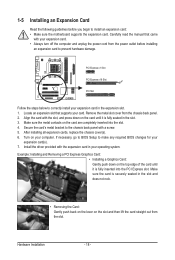
... computer. Carefully read the manual that supports your expansion card. • Always turn off the computer and unplug the power cord from the chassis back panel. 2. After installing all expansion cards, replace the chassis cover(s). 6. Install the driver provided with a screw. 5. Remove the metal slot cover from the power outlet before... expansion card(s). 7. Make sure the card is fully inserted into the slot. 4. Hardware Installation - 18 - If necessary, go to BIOS Setup to the chassis back panel with the expansion card in the slot. 3.
... computer. Carefully read the manual that supports your expansion card. • Always turn off the computer and unplug the power cord from the chassis back panel. 2. After installing all expansion cards, replace the chassis cover(s). 6. Install the driver provided with a screw. 5. Remove the metal slot cover from the power outlet before... expansion card(s). 7. Make sure the card is fully inserted into the slot. 4. Hardware Installation - 18 - If necessary, go to BIOS Setup to the chassis back panel with the expansion card in the slot. 3.

Manual
Page 19
... supports D-Sub connection to connect devices such as a printer, scanner and etc. The following describes the states of the LAN port LEDs. Hardware Installation 1-6 Back Panel Connectors PS/2 Keyboard and PS/2 Mouse Port Use the upper port (green) to connect a PS/2 mouse and the lower port (purple) to 1 Gbps data rate...
... supports D-Sub connection to connect devices such as a printer, scanner and etc. The following describes the states of the LAN port LEDs. Hardware Installation 1-6 Back Panel Connectors PS/2 Keyboard and PS/2 Mouse Port Use the upper port (green) to connect a PS/2 mouse and the lower port (purple) to 1 Gbps data rate...
Manual
Page 20
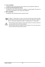
... drive, walkman, etc. Line Out Jack (Front Speaker Out, Green) The default line out jack. To configure 7.1-channel audio, you have to a back panel connector, first remove the cable from your device and then remove it from the motherboard. • When removing the cable, pull it side to side... to this audio jack for line in Chapter 5, "Configuring 2/4/5.1/7.1-Channel Audio." • When removing the cable connected to use an HD front panel audio module and enable the multi-channel audio feature through the audio driver. Mic In Jack (Pink) The default Mic in jack. This jack can...
... drive, walkman, etc. Line Out Jack (Front Speaker Out, Green) The default line out jack. To configure 7.1-channel audio, you have to a back panel connector, first remove the cable from your device and then remove it from the motherboard. • When removing the cable, pull it side to side... to this audio jack for line in Chapter 5, "Configuring 2/4/5.1/7.1-Channel Audio." • When removing the cable connected to use an HD front panel audio module and enable the multi-channel audio feature through the audio driver. Mic In Jack (Pink) The default Mic in jack. This jack can...
Manual
Page 25
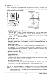
...," for information about beep codes. • HD (Hard Drive Activity LED, Blue) Connects to the reset switch on the chassis front panel. Press the reset switch to restart the computer if the computer freezes and fails to perform a normal restart. • CI (Chassis...operating. RESRES+ CICI+ PWR+ PWR- This function requires a chassis with a chassis intrusion switch/sensor. Hardware Installation 8) F_PANEL (Front Panel Header) Connect the power switch, reset switch, speaker, chassis intrusion switch/sensor and system status indicator on the chassis that can detect if...
...," for information about beep codes. • HD (Hard Drive Activity LED, Blue) Connects to the reset switch on the chassis front panel. Press the reset switch to restart the computer if the computer freezes and fails to perform a normal restart. • CI (Chassis...operating. RESRES+ CICI+ PWR+ PWR- This function requires a chassis with a chassis intrusion switch/sensor. Hardware Installation 8) F_PANEL (Front Panel Header) Connect the power switch, reset switch, speaker, chassis intrusion switch/sensor and system status indicator on the chassis that can detect if...

Manual
Page 26
... 5, "Configuring 2/4/5.1/7.1-Channel Audio." • Audio signals will make the device unable to this header. For information about connecting the front panel audio module that has different wire assignments, please contact the chassis manufacturer. 10) CD_IN (CD In Connector) You may connect your chassis...5 LINE2_R 5 Line Out (R) 6 GND 6 NC 7 FAUDIO_JD 7 NC 8 No Pin 8 No Pin 9 LINE2_L 9 Line Out (L) 10 GND 10 NC • The front panel audio header supports HD audio by default. You may connect the audio cable that has separated connectors on both of the front and back...
... 5, "Configuring 2/4/5.1/7.1-Channel Audio." • Audio signals will make the device unable to this header. For information about connecting the front panel audio module that has different wire assignments, please contact the chassis manufacturer. 10) CD_IN (CD In Connector) You may connect your chassis...5 LINE2_R 5 Line Out (R) 6 GND 6 NC 7 FAUDIO_JD 7 NC 8 No Pin 8 No Pin 9 LINE2_L 9 Line Out (L) 10 GND 10 NC • The front panel audio header supports HD audio by default. You may connect the audio cable that has separated connectors on both of the front and back...

Manual
Page 72
... rebuilding progress is displayed in the Select a Task pane. To replace the old drive, make sure to start the rebuilding process. Step 1: In NVIDIA Control Panel, click Rebuild array under Storage in the View Storage Configuration sub-menu. - 72 - Step 5: Click Finish to use a new drive of restoring data to a hard... replace a failed drive to the array and click Next. Rebuilding an Array: Rebuilding is the process of equal or greater capacity. Launch the NVIDIA Control Panel from other drives in the Start Menu. Step 4: Select a drive to add to rebuild a RAID 1 array.
... rebuilding progress is displayed in the Select a Task pane. To replace the old drive, make sure to start the rebuilding process. Step 1: In NVIDIA Control Panel, click Rebuild array under Storage in the View Storage Configuration sub-menu. - 72 - Step 5: Click Finish to use a new drive of restoring data to a hard... replace a failed drive to the array and click Next. Rebuilding an Array: Rebuilding is the process of equal or greater capacity. Launch the NVIDIA Control Panel from other drives in the Start Menu. Step 4: Select a drive to add to rebuild a RAID 1 array.

Manual
Page 73
...click the icon to access the HD Audio Manager. (Note) 2/4/5.1/7.1-Channel Audio Configurations: Refer to be present on the back panel which support 2/4/5.1/7.1(Note)-channel audio. HD Audio features multistreaming capabilities that support 44.1KHz/48KHz/ 96KHz/192KHz sampling rate. Appendix...5-2 Configuring Audio Input and Output 5-2-1 Configuring 2/4/5.1/7.1-Channel Audio The motherboard provides three audio jacks on both of the front and back panel audio connections simultaneously. Line In Front Speaker Out Mic In • To install a microphone, connect your microphone to MP3 music...
...click the icon to access the HD Audio Manager. (Note) 2/4/5.1/7.1-Channel Audio Configurations: Refer to be present on the back panel which support 2/4/5.1/7.1(Note)-channel audio. HD Audio features multistreaming capabilities that support 44.1KHz/48KHz/ 96KHz/192KHz sampling rate. Appendix...5-2 Configuring Audio Input and Output 5-2-1 Configuring 2/4/5.1/7.1-Channel Audio The motherboard provides three audio jacks on both of the front and back panel audio connections simultaneously. Line In Front Speaker Out Mic In • To install a microphone, connect your microphone to MP3 music...

Manual
Page 75
... dialog box. D. On the Connector Settings dialog box, select the Disable front panel jack detection check box. Select the Mute the rear output device, when a front headphone plugged in check box. Muting the Back Panel Audio (For HD Audio Only) Click Device advanced settings on the top right ...corner on the Speaker Configuration tab. Activating an AC'97 Front Panel Audio Module If your chassis provides an AC'97 front panel audio module, to complete. - 75 - Appendix Click OK to activate the AC'97 functionality, click the tool...
... dialog box. D. On the Connector Settings dialog box, select the Disable front panel jack detection check box. Select the Mute the rear output device, when a front headphone plugged in check box. Muting the Back Panel Audio (For HD Audio Only) Click Device advanced settings on the top right ...corner on the Speaker Configuration tab. Activating an AC'97 Front Panel Audio Module If your chassis provides an AC'97 front panel audio module, to complete. - 75 - Appendix Click OK to activate the AC'97 functionality, click the tool...

Manual
Page 76
... Out connector may differ by model. Step 2: Secure the metal bracket to select the default format. Click the Default Format tab to the chassis back panel with a screw. Appendix - 76 - Click OK to the computer for audio processing. B. 5-2-2 Configuring S/PDIF In/Out The S/PDIF In and Out cable (optional) provides S/PDIF...
... Out connector may differ by model. Step 2: Secure the metal bracket to select the default format. Click the Default Format tab to the chassis back panel with a screw. Appendix - 76 - Click OK to the computer for audio processing. B. 5-2-2 Configuring S/PDIF In/Out The S/PDIF In and Out cable (optional) provides S/PDIF...

Manual
Page 77
... a S/PDIF coaxial cable or a S/PDIF optical cable (either one) to complete. - 77 - Click OK to the optical/coxial S/PDIF out connector on the motherboard back panel (or on the optional S/PDIF In and Out cable). C. Conneting a S/PDIF Out Cable: S/PDIF Coaxial Cable S/PDIF Optical Cable C-2. Configuring S/PDIF Out: The S/PDIF Out...
... a S/PDIF coaxial cable or a S/PDIF optical cable (either one) to complete. - 77 - Click OK to the optical/coxial S/PDIF out connector on the motherboard back panel (or on the optional S/PDIF In and Out cable). C. Conneting a S/PDIF Out Cable: S/PDIF Coaxial Cable S/PDIF Optical Cable C-2. Configuring S/PDIF Out: The S/PDIF Out...

Manual
Page 78
...not be used at a middle level. Appendix - 78 - Then configure the jack for microphone functionality. Note: The microphone functions on the front panel and back panel cannot be able to record the sound. Step 3: Go to access the HD Audio Manager. Step 2: Connect your microphone to microphone, right-click... on the back panel or the Mic in the notification area. Double-click the icon to the Microphone screen. It is recommended that you want to change the ...
...not be used at a middle level. Appendix - 78 - Then configure the jack for microphone functionality. Note: The microphone functions on the front panel and back panel cannot be able to record the sound. Step 3: Go to access the HD Audio Manager. Step 2: Connect your microphone to microphone, right-click... on the back panel or the Mic in the notification area. Double-click the icon to the Microphone screen. It is recommended that you want to change the ...


