Manual
Page 1
GA-M61VME-S2 (rev. 2.0) AMD Socket AM2 Processor Motherboard User's Manual Rev. 2002 12ME-M61VMES2-2002R * The WEEE marking on the product indicates this product must not be disposed of with user's other household waste and must be handed over to a designated collection point for the recycling of waste electrical and electronic equipment!! * The WEEE marking applies only in European Union's member states.
GA-M61VME-S2 (rev. 2.0) AMD Socket AM2 Processor Motherboard User's Manual Rev. 2002 12ME-M61VMES2-2002R * The WEEE marking on the product indicates this product must not be disposed of with user's other household waste and must be handed over to a designated collection point for the recycling of waste electrical and electronic equipment!! * The WEEE marking applies only in European Union's member states.
Manual
Page 2
Motherboard GA-M61VME-S2 Sept. 5, 2006 Motherboard GA-M61VME-S2 Sept. 5, 2006
Motherboard GA-M61VME-S2 Sept. 5, 2006 Motherboard GA-M61VME-S2 Sept. 5, 2006
Manual
Page 4
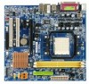
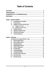
Table of Contents ItemChecklist ...6 OptionalAccessories ...6 GA-M61VME-S2 (rev. 2.0) Motherboard Layout 7 Block Diagram ...8 Chapter 1 Hardware Installation 9 1-1 Considerations Prior to Installation 9 1-2 Feature Summary 10 1-3 Installation of the CPU and CPU Cooler 12 1-3-1 Installation of the CPU ...
Table of Contents ItemChecklist ...6 OptionalAccessories ...6 GA-M61VME-S2 (rev. 2.0) Motherboard Layout 7 Block Diagram ...8 Chapter 1 Hardware Installation 9 1-1 Considerations Prior to Installation 9 1-2 Feature Summary 10 1-3 Installation of the CPU and CPU Cooler 12 1-3-1 Installation of the CPU ...
Manual
Page 9
... its components. 5. Damage due to improper installation. 4. Hardware Installation Please do not allow screws to come in contact with the motherboard circuit or its power cord. 2. Damage due to be an unofficial Gigabyte product. - 9 - Product determined to natural disaster, accident or human cause. 2. Please make sure there are connected. 4. These stickers are...
... its components. 5. Damage due to improper installation. 4. Hardware Installation Please do not allow screws to come in contact with the motherboard circuit or its power cord. 2. Damage due to be an unofficial Gigabyte product. - 9 - Product determined to natural disaster, accident or human cause. 2. Please make sure there are connected. 4. These stickers are...
Manual
Page 10
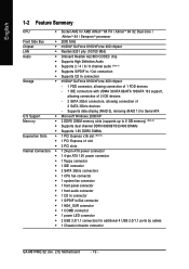
... 3Gb/s connectors, allowing connection of 2 SATA 3Gb/s devices - English 1-2 Feature Summary CPU Š Socket AM2 for additional 4 USB 2.0/1.1 ports by cables Š 1 Chassis Intrusion connector GA-M61VME-S2 (rev. 2.0) Motherboard - 10 -
... 3Gb/s connectors, allowing connection of 2 SATA 3Gb/s devices - English 1-2 Feature Summary CPU Š Socket AM2 for additional 4 USB 2.0/1.1 ports by cables Š 1 Chassis Intrusion connector GA-M61VME-S2 (rev. 2.0) Motherboard - 10 -
Manual
Page 11
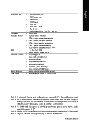
... PCI Express x1 mode. (please refer to the limitation of physical memory is supported will depend on different motherboards. - 11 - Hardware Installation Windows 64-bit operating system doesn't have such limitation. (Note 3) The GA-M61VME-S2 supports up an 8 channel audio configuration, you install. (Note 5) EasyTune functions may vary depending on the CPU you...
... PCI Express x1 mode. (please refer to the limitation of physical memory is supported will depend on different motherboards. - 11 - Hardware Installation Windows 64-bit operating system doesn't have such limitation. (Note 3) The GA-M61VME-S2 supports up an 8 channel audio configuration, you install. (Note 5) EasyTune functions may vary depending on the CPU you...
Manual
Page 12
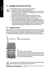
... positioning of the CPU. Move the socket lever to the unlocked position as shown in Fig. 1 (90o to the plane of the motherboard) prior to system use extra care when installing the CPU. Once the CPU is not recommended that corresponds to a triangle marking on the... frequency in the wrong direction, the CPU will not fit if positioned incorrectly. Socket Lever Fig.1 Position lever at a 90 degree angle. GA-M61VME-S2 (rev. 2.0) Motherboard - 12 - The CPU will not insert properly. English 1-3 Installation of the CPU and CPU Cooler Before installing the CPU, please comply ...
... positioning of the CPU. Move the socket lever to the unlocked position as shown in Fig. 1 (90o to the plane of the motherboard) prior to system use extra care when installing the CPU. Once the CPU is not recommended that corresponds to a triangle marking on the... frequency in the wrong direction, the CPU will not fit if positioned incorrectly. Socket Lever Fig.1 Position lever at a 90 degree angle. GA-M61VME-S2 (rev. 2.0) Motherboard - 12 - The CPU will not insert properly. English 1-3 Installation of the CPU and CPU Cooler Before installing the CPU, please comply ...
Manual
Page 13
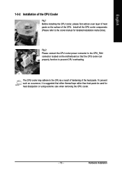
English 1-3-2 Installation of the CPU Cooler Fig.1 Before installing the CPU cooler, please first add an even layer of heat paste on the motherboard so that either thermal tape rather than heat paste be used for detailed installation instructions). Fig.2 Please connect the CPU cooler power connector to prevent ...
English 1-3-2 Installation of the CPU Cooler Fig.1 Before installing the CPU cooler, please first add an even layer of heat paste on the motherboard so that either thermal tape rather than heat paste be used for detailed installation instructions). Fig.2 Please connect the CPU cooler power connector to prevent ...
Manual
Page 14
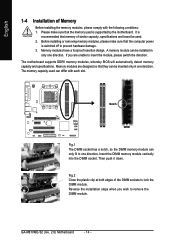
Memory modules have a foolproof insertion design. The motherboard supports DDRII memory modules, whereby BIOS will automatically detect memory capacity and specifications. Notch DDRII Fig.1 ...module can be used. 2. Please make sure that they can only fit in only one direction. It is supported by the motherboard. If you wish to prevent hardware damage. 3. Memory modules are unable to lock the DIMM module. Then push it down....when you are designed so that the computer power is switched off to remove the DIMM module. GA-M61VME-S2 (rev. 2.0) Motherboard - 14 -
Memory modules have a foolproof insertion design. The motherboard supports DDRII memory modules, whereby BIOS will automatically detect memory capacity and specifications. Notch DDRII Fig.1 ...module can be used. 2. Please make sure that they can only fit in only one direction. It is supported by the motherboard. If you wish to prevent hardware damage. 3. Memory modules are unable to lock the DIMM module. Then push it down....when you are designed so that the computer power is switched off to remove the DIMM module. GA-M61VME-S2 (rev. 2.0) Motherboard - 14 -
Manual
Page 15
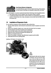
... in motherboard. 4. Due to the onboard PCI Express x16 slot and press firmly down on the computer, if necessary, setup BIOS utility of Expansion Cards You can install your computer's chassis cover, screws and slot bracket from BIOS. 8. Replace the screw to release the card. English Dual Channel Memory Configuration The GA-M61VME-S2...
... in motherboard. 4. Due to the onboard PCI Express x16 slot and press firmly down on the computer, if necessary, setup BIOS utility of Expansion Cards You can install your computer's chassis cover, screws and slot bracket from BIOS. 8. Replace the screw to release the card. English Dual Channel Memory Configuration The GA-M61VME-S2...
Manual
Page 16
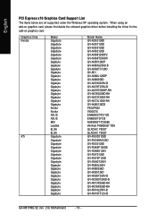
... Chip Nvidia ATi Maker Gigabyte Gigabyte Gigabyte Gigabyte Gigabyte Gigabyte Gigabyte Gigabyte Gigabyte Gigabyte Gigabyte Gigabyte Gigabyte Gigabyte Gigabyte Gigabyte Gigabyte Gigabyte Gigabyte Nvidia Nvidia ASUS ASUS MSI Leadtek ELSA ELSA Gigabyte Gigabyte Gigabyte Gigabyte Gigabyte Gigabyte Gigabyte Gigabyte Gigabyte Gigabyte Gigabyte Gigabyte Gigabyte Gigabyte Gigabyte Gigabyte Gigabyte Model Name GV-NX53128D GV...GV-RX13P256D-RH GV-RX16P256D-RH GV-RX18L256V-B GV-RX18T512V-B GA-M61VME-S2 (rev. 2.0) Motherboard - 16 - English PCI Express x16 Graphics Card Support List The items ...
... Chip Nvidia ATi Maker Gigabyte Gigabyte Gigabyte Gigabyte Gigabyte Gigabyte Gigabyte Gigabyte Gigabyte Gigabyte Gigabyte Gigabyte Gigabyte Gigabyte Gigabyte Gigabyte Gigabyte Gigabyte Gigabyte Nvidia Nvidia ASUS ASUS MSI Leadtek ELSA ELSA Gigabyte Gigabyte Gigabyte Gigabyte Gigabyte Gigabyte Gigabyte Gigabyte Gigabyte Gigabyte Gigabyte Gigabyte Gigabyte Gigabyte Gigabyte Gigabyte Gigabyte Model Name GV-NX53128D GV...GV-RX13P256D-RH GV-RX16P256D-RH GV-RX18L256V-B GV-RX18T512V-B GA-M61VME-S2 (rev. 2.0) Motherboard - 16 - English PCI Express x16 Graphics Card Support List The items ...
Manual
Page 18
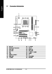
English 1-7 Connectors Introduction 1 2 3 16 5 10 13 17 7 18 14 11 12 15 6 48 9 1) ATX_12V 2) ATX (Power Connector) 3) CPU_FAN 4) SYS_FAN 5) IDE 6) FDD 7) SATAII 0 / SATAII 1 8) PWR_LED 9) F_PANEL 10) F_AUDIO 11) CD_IN 12) SPDIF_IO 13) HDA_SUR 14) F_USB1 / F_USB2 15) COMB 16) CI 17) CLR_CMOS 18) BATTERY GA-M61VME-S2 (rev. 2.0) Motherboard - 18 -
English 1-7 Connectors Introduction 1 2 3 16 5 10 13 17 7 18 14 11 12 15 6 48 9 1) ATX_12V 2) ATX (Power Connector) 3) CPU_FAN 4) SYS_FAN 5) IDE 6) FDD 7) SATAII 0 / SATAII 1 8) PWR_LED 9) F_PANEL 10) F_AUDIO 11) CD_IN 12) SPDIF_IO 13) HDA_SUR 14) F_USB1 / F_USB2 15) COMB 16) CI 17) CLR_CMOS 18) BATTERY GA-M61VME-S2 (rev. 2.0) Motherboard - 18 -
Manual
Page 19
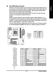
.... If the ATX_12V power connector is unable to all components and devices are properly installed. Align the power connector with its proper location on the motherboard before plugging in the power cord ; Caution! If a power supply is used (300W or greater). Before connecting the power connector, please make sure that... . It is able to the CPU. Please use a 24-pin ATX power supply, please remove the small cover on the power connector on the motherboard and connect tightly. If you use a power supply that is recommended that a power supply that all the components on the...
.... If the ATX_12V power connector is unable to all components and devices are properly installed. Align the power connector with its proper location on the motherboard before plugging in the power cord ; Caution! If a power supply is used (300W or greater). Before connecting the power connector, please make sure that... . It is able to the CPU. Please use a 24-pin ATX power supply, please remove the small cover on the power connector on the motherboard and connect tightly. If you use a power supply that is recommended that a power supply that all the components on the...
Manual
Page 20
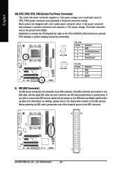
... connector and possesses a foolproof connection design. Before attaching the IDE cable, please take note of the foolproof groove in the IDE connector. 40 39 2 1 GA-M61VME-S2 (rev. 2.0) Motherboard - 20 - The black connector wire is the ground wire (GND). Remember to connect the CPU/system fan cable to the CPU_FAN/SYS_FAN connector to prevent...
... connector and possesses a foolproof connection design. Before attaching the IDE cable, please take note of the foolproof groove in the IDE connector. 40 39 2 1 GA-M61VME-S2 (rev. 2.0) Motherboard - 20 - The black connector wire is the ground wire (GND). Remember to connect the CPU/system fan cable to the CPU_FAN/SYS_FAN connector to prevent...
Manual
Page 22
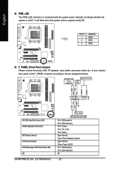
...+ MSG- RESRES+ NC HD (IDE Hard Disk Active LED) SPEAK (Speaker Connector) RES (Reset Switch) PW (Power Switch) MSG (Message LED/Power/Sleep LED) NC GA-M61VME-S2 (rev. 2.0) Motherboard Reset Switch IDE Hard Disk Active LED Pin 1: LED anode(+) Pin 2: LED cathode(-) Pin 1: Power Pin 2- Definition 1 MPD+ 1 2 MPD- 3 MPD- 9) F_PANEL (Front Panel Jumper...
...+ MSG- RESRES+ NC HD (IDE Hard Disk Active LED) SPEAK (Speaker Connector) RES (Reset Switch) PW (Power Switch) MSG (Message LED/Power/Sleep LED) NC GA-M61VME-S2 (rev. 2.0) Motherboard Reset Switch IDE Hard Disk Active LED Pin 1: LED anode(+) Pin 2: LED cathode(-) Pin 1: Power Pin 2- Definition 1 MPD+ 1 2 MPD- 3 MPD- 9) F_PANEL (Front Panel Jumper...
Manual
Page 24
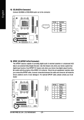
... unable to the connector. For optional S/PDIF cable, please contact your local dealer. 51 62 Pin No. 1 2 3 4 5 6 Definition Power No Pin SPDIF SPDIFI GND GND GA-M61VME-S2 (rev. 2.0) Motherboard - 24 - English 11) CD_IN (CD In Connector) Connect CD-ROM or DVD-ROM audio out to work or even damage it.
... unable to the connector. For optional S/PDIF cable, please contact your local dealer. 51 62 Pin No. 1 2 3 4 5 6 Definition Power No Pin SPDIF SPDIFI GND GND GA-M61VME-S2 (rev. 2.0) Motherboard - 24 - English 11) CD_IN (CD In Connector) Connect CD-ROM or DVD-ROM audio out to work or even damage it.
Manual
Page 26
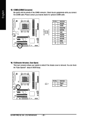
... dealer for optional COMB cable. Pin No. Please contact your system to detect if the chassis cover is removed. Pin No. Definition 1 1 Signal 2 GND GA-M61VME-S2 (rev. 2.0) Motherboard - 26 - You can check the "Case Opened" status in BIOS Setup. Check the pin assignments while you connect the COMB cable. English 15) COMB (COMB...
... dealer for optional COMB cable. Pin No. Please contact your system to detect if the chassis cover is removed. Pin No. Definition 1 1 Signal 2 GND GA-M61VME-S2 (rev. 2.0) Motherboard - 26 - You can check the "Case Opened" status in BIOS Setup. Check the pin assignments while you connect the COMB cable. English 15) COMB (COMB...
Manual
Page 28
English GA-M61VME-S2 (rev. 2.0) Motherboard - 28 -
English GA-M61VME-S2 (rev. 2.0) Motherboard - 28 -
Manual
Page 29
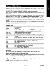
... activate certain system features. CMOS Profiles Main Menu The on-line description of the highlighted setup function is displayed at the bottom of the motherboard. Because BIOS flashing is turned off, the battery on , pressing the button during the BIOS POST (Power-On Self Test) will take... Page Setup Menu and Option Page Setup Menu - When the power is a Windows-based utility that describes the appropriate keys to a new BIOS, either Gigabyte's Q-Flash or @BIOS utility can enter the BIOS setup screen by pressing "Ctrl + F1". To exit the Help Window press . English Chapter 2...
... activate certain system features. CMOS Profiles Main Menu The on-line description of the highlighted setup function is displayed at the bottom of the motherboard. Because BIOS flashing is turned off, the battery on , pressing the button during the BIOS POST (Power-On Self Test) will take... Page Setup Menu and Option Page Setup Menu - When the power is a Windows-based utility that describes the appropriate keys to a new BIOS, either Gigabyte's Q-Flash or @BIOS utility can enter the BIOS setup screen by pressing "Ctrl + F1". To exit the Help Window press . English Chapter 2...
Manual
Page 30
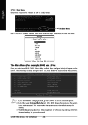
Press to exit this chapter are for reference only and may differ from the exact settings for your motherboard. Select the Load Optimized Defaults item in this menu. English : Boot Menu Select boot sequence for stability. 3. CMOS Setup Utility-Copyright (C)... Setup Time, Date, Hard Disk Type... 1. If you don't find the settings you enter Award BIOS CMOS Setup Utility, the Main Menu (as usual. GA-M61VME-S2 (rev. 2.0) Motherboard - 30 - GA-M61VME-S2 F6a . . . . :BIOS Setup/Q-Flash :Xpress Recovery2 :Boot Menu :Qflash 12/15/2006-NV-MCP61-6A61KG03C-00 :Boot Menu Use < > or < >...
Press to exit this chapter are for reference only and may differ from the exact settings for your motherboard. Select the Load Optimized Defaults item in this menu. English : Boot Menu Select boot sequence for stability. 3. CMOS Setup Utility-Copyright (C)... Setup Time, Date, Hard Disk Type... 1. If you don't find the settings you enter Award BIOS CMOS Setup Utility, the Main Menu (as usual. GA-M61VME-S2 (rev. 2.0) Motherboard - 30 - GA-M61VME-S2 F6a . . . . :BIOS Setup/Q-Flash :Xpress Recovery2 :Boot Menu :Qflash 12/15/2006-NV-MCP61-6A61KG03C-00 :Boot Menu Use < > or < >...


