Manual
Page 4
... the CPU and CPU Cooler 12 1-3-1 Installation of the CPU 12 1-3-2 Installation of the CPU Cooler 13 1-4 Installation of Memory 14 1-5 Installation of Expansion Cards 15 1-6 I/O Back Panel Introduction 17 1-7 Connectors Introduction 18 Chapter 2 BIOS Setup 29 The Main Menu (For example: BIOS Ver. : F6a 30 2-1 Standard CMOS Features 32 2-2 Advanced BIOS Features 34 2-3 IntegratedPeripherals 36 2-4 Power Management Setup 39 2-5 PnP/PCI Configurations 41 2-6 PC Health Status 42 2-7 Load Fail-Safe Defaults 44 2-8 Load Optimized Defaults 44 2-9 Set Supervisor/User Password...
... the CPU and CPU Cooler 12 1-3-1 Installation of the CPU 12 1-3-2 Installation of the CPU Cooler 13 1-4 Installation of Memory 14 1-5 Installation of Expansion Cards 15 1-6 I/O Back Panel Introduction 17 1-7 Connectors Introduction 18 Chapter 2 BIOS Setup 29 The Main Menu (For example: BIOS Ver. : F6a 30 2-1 Standard CMOS Features 32 2-2 Advanced BIOS Features 34 2-3 IntegratedPeripherals 36 2-4 Power Management Setup 39 2-5 PnP/PCI Configurations 41 2-6 PC Health Status 42 2-7 Load Fail-Safe Defaults 44 2-8 Load Optimized Defaults 44 2-9 Set Supervisor/User Password...
Manual
Page 10
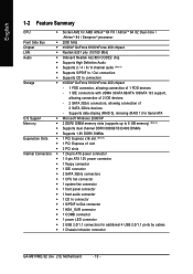
... Windows 2000/XP Memory Š 2 DDRII DIMM memory slots (supports up to 8 GB memory) (Note 2) Š Supports dual channel DDRII 800/667/533/400 DIMMs Š Supports 1.8V DDRII DIMMs Expanstion Slots Š 1 PCI Express x16 slot (Note 3) Š 1 PCI Express x1 slot Š 2 PCI slots Internal Connectors Š 1 24-pin ATX power connector Š 1 4-pin ATX 12V power connector Š 1 floppy connector Š 1 IDE connector Š 2 SATA 3Gb/s connectors Š 1 CPU fan connector Š 1 system fan connector Š 1 front panel connector Š 1 front audio connector...
... Windows 2000/XP Memory Š 2 DDRII DIMM memory slots (supports up to 8 GB memory) (Note 2) Š Supports dual channel DDRII 800/667/533/400 DIMMs Š Supports 1.8V DDRII DIMMs Expanstion Slots Š 1 PCI Express x16 slot (Note 3) Š 1 PCI Express x1 slot Š 2 PCI slots Internal Connectors Š 1 24-pin ATX power connector Š 1 4-pin ATX 12V power connector Š 1 floppy connector Š 1 IDE connector Š 2 SATA 3Gb/s connectors Š 1 CPU fan connector Š 1 system fan connector Š 1 front panel connector Š 1 front audio connector...
Manual
Page 11
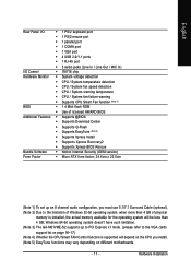
... keyboard port Š 1 PS/2 mouse port Š 1 parallel port Š 1 COMA port Š 1 VGA port Š 4 USB 2.0/1.1 ports Š 1 RJ-45 port Š 3 audio jacks (Line In / Line Out / MIC In) I/O Control Š IT8716 chip Hardware Monitor Š System voltage detection Š CPU / System temperature detection Š CPU / System fan speed detection Š CPU / System warning temperature Š CPU / System fan failure warning Š Supports CPU Smart Fan function (Note 4) BIOS Š 1 4 Mbit flash ROM Š Use of physical memory is installed, the actual memory...
... keyboard port Š 1 PS/2 mouse port Š 1 parallel port Š 1 COMA port Š 1 VGA port Š 4 USB 2.0/1.1 ports Š 1 RJ-45 port Š 3 audio jacks (Line In / Line Out / MIC In) I/O Control Š IT8716 chip Hardware Monitor Š System voltage detection Š CPU / System temperature detection Š CPU / System fan speed detection Š CPU / System warning temperature Š CPU / System fan failure warning Š Supports CPU Smart Fan function (Note 4) BIOS Š 1 4 Mbit flash ROM Š Use of physical memory is installed, the actual memory...
Manual
Page 15
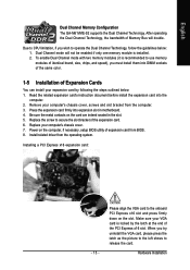
... onboard PCI Express x16 slot and press firmly down on the slot. Dual Channel mode will double. Power on the card are indeed seated in motherboard. 4. Remove your expansion card by the latch at the end of Expansion Cards You can install your computer's chassis cover, screws and slot bracket from BIOS. 8. Install related driver from the operating system. When you wish to use memory modules of identical brand, size, chips, and speed), you must install...
... onboard PCI Express x16 slot and press firmly down on the slot. Dual Channel mode will double. Power on the card are indeed seated in motherboard. 4. Remove your expansion card by the latch at the end of Expansion Cards You can install your computer's chassis cover, screws and slot bracket from BIOS. 8. Install related driver from the operating system. When you wish to use memory modules of identical brand, size, chips, and speed), you must install...
Manual
Page 20
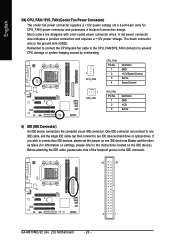
...1 GA-M61VME-S2 (rev. 2.0) Motherboard - 20 - A red power connector wire indicates a positive connection and requires a +12V power voltage. Remember to connect the CPU/system fan cable to the CPU_FAN/SYS_FAN connector to prevent CPU damage or system hanging caused by overheating. 1 CPU_FAN CPU_FAN: Pin No. 1 2 3 4 Definition GND +12V/Speed Control Sense Speed Control 1 SYS_FAN SYS_FAN: Pin No. 1 2 3 Definition GND +12V Sense 5) IDE (IDE Connector) An IDE device connects to two IDE devices (hard drive or optical drive). English 3/4) CPU_FAN / SYS_FAN (Cooler Fan Power Connector) The...
...1 GA-M61VME-S2 (rev. 2.0) Motherboard - 20 - A red power connector wire indicates a positive connection and requires a +12V power voltage. Remember to connect the CPU/system fan cable to the CPU_FAN/SYS_FAN connector to prevent CPU damage or system hanging caused by overheating. 1 CPU_FAN CPU_FAN: Pin No. 1 2 3 4 Definition GND +12V/Speed Control Sense Speed Control 1 SYS_FAN SYS_FAN: Pin No. 1 2 3 Definition GND +12V Sense 5) IDE (IDE Connector) An IDE device connects to two IDE devices (hard drive or optical drive). English 3/4) CPU_FAN / SYS_FAN (Cooler Fan Power Connector) The...

Manual
Page 21
... FDD connector is used to connect the FDD cable while the other end of the foolproof groove in order to work properly. 7 1 SATAII 0 SATAII 1 1 7 Pin No. 1 2 3 4 5 6 7 Definition GND TXP TXN GND RXN RXP GND - 21 - Hardware Installation The types of FDD drives supported are: 360 KB, 720 KB, 1.2 MB, 1.44 MB and 2.88 MB. Please refer to the BIOS setting for the SATA...
... FDD connector is used to connect the FDD cable while the other end of the foolproof groove in order to work properly. 7 1 SATAII 0 SATAII 1 1 7 Pin No. 1 2 3 4 5 6 7 Definition GND TXP TXN GND RXN RXP GND - 21 - Hardware Installation The types of FDD drives supported are: 360 KB, 720 KB, 1.2 MB, 1.44 MB and 2.88 MB. Please refer to the BIOS setting for the SATA...
Manual
Page 22
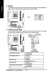
... NC HD (IDE Hard Disk Active LED) SPEAK (Speaker Connector) RES (Reset Switch) PW (Power Switch) MSG (Message LED/Power/Sleep LED) NC GA-M61VME-S2 (rev. 2.0) Motherboard Reset Switch IDE Hard Disk Active LED Pin 1: LED anode(+) Pin 2: LED cathode(-) Pin 1: Power Pin 2- English 8) PWR_LED The PWR_LED connector is connected with the system power indicator to the pin assignment below. Pin No. Definition 1 MPD+ 1 2 MPD- 3 MPD- 9) F_PANEL (Front Panel Jumper) Please connect the power LED, PC speaker, reset switch and power switch etc. It will blink when the system enters suspend mode(S1...
... NC HD (IDE Hard Disk Active LED) SPEAK (Speaker Connector) RES (Reset Switch) PW (Power Switch) MSG (Message LED/Power/Sleep LED) NC GA-M61VME-S2 (rev. 2.0) Motherboard Reset Switch IDE Hard Disk Active LED Pin 1: LED anode(+) Pin 2: LED cathode(-) Pin 1: Power Pin 2- English 8) PWR_LED The PWR_LED connector is connected with the system power indicator to the pin assignment below. Pin No. Definition 1 MPD+ 1 2 MPD- 3 MPD- 9) F_PANEL (Front Panel Jumper) Please connect the power LED, PC speaker, reset switch and power switch etc. It will blink when the system enters suspend mode(S1...
Manual
Page 32
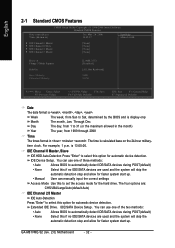
... IDE/SATA devices during POST(default) • None Select this to select this option for the hard drive. Extended IDE Drive. English 2-1 Standard CMOS Features Date (mm:dd:yy) Time (hh:mm:ss) CMOS Setup Utility-Copyright (C) 1984-2006 Award Software Standard CMOS Features Tue, Mar 28 2006 14:42:37 Item Help Menu Level` ` IDE Channel 0 Master ` IDE Channel 0 Slave ` IDE Channel 2 Master ` IDE Channel 3 Master [None] [None] [None] [None] Drive A Floppy 3 Mode Support Halt On Base Memory Extended Memory [1.44M, 3.5"] [Disabled...
... IDE/SATA devices during POST(default) • None Select this to select this option for the hard drive. Extended IDE Drive. English 2-1 Standard CMOS Features Date (mm:dd:yy) Time (hh:mm:ss) CMOS Setup Utility-Copyright (C) 1984-2006 Award Software Standard CMOS Features Tue, Mar 28 2006 14:42:37 Item Help Menu Level` ` IDE Channel 0 Master ` IDE Channel 0 Slave ` IDE Channel 2 Master ` IDE Channel 3 Master [None] [None] [None] [None] Drive A Floppy 3 Mode Support Halt On Base Memory Extended Memory [1.44M, 3.5"] [Disabled...
Manual
Page 37
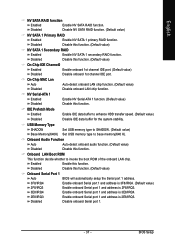
...) Set USB memory type to invoke the boot ROM of the onboard LAN chip. On-Chip MAC Lan Auto Auto-detect onboard LAN chip function. (Default value) Disabled Disable onboard LAN chip function. NV Serial-ATA 1 Enabled Enable NV Serial-ATA 1 function. (Default value) Disabled Disable this function. (Default value) NV SATA 1 Secondary RAID Enabled Disabled Enable NV SATA 1 secondary RAID function. Onboard LAN Boot ROM This function decide whether to base memory(640 K). Enabled Enable this function. (Default value) Onboard Serial Port 1 Auto BIOS will automatically setup the...
...) Set USB memory type to invoke the boot ROM of the onboard LAN chip. On-Chip MAC Lan Auto Auto-detect onboard LAN chip function. (Default value) Disabled Disable onboard LAN chip function. NV Serial-ATA 1 Enabled Enable NV Serial-ATA 1 function. (Default value) Disabled Disable this function. (Default value) NV SATA 1 Secondary RAID Enabled Disabled Enable NV SATA 1 secondary RAID function. Onboard LAN Boot ROM This function decide whether to base memory(640 K). Enabled Enable this function. (Default value) Onboard Serial Port 1 Auto BIOS will automatically setup the...
Manual
Page 38
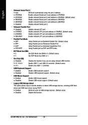
... controller. Enabled BIOS will automatically setup the port 2 address. 3F8/IRQ4 2F8/IRQ3 Enable onboard Serial port 2 and address is 3BC/IRQ7. Disabled Disable onboard Serial port 2. ECP Mode Use DMA 3 Set ECP Mode Use DMA to 3. (Default value) 1 Set ECP Mode Use DMA to detect USB storage devices, including USB flash drives and USB hard drives during POST. USB Keyboard Support Enabled Disabled Enable USB keyboard support. Using Parallel port as Extended Capabilities Port. Disabled Disable USB mouse support. (Default value) Legacy USB Storage detect This option...
... controller. Enabled BIOS will automatically setup the port 2 address. 3F8/IRQ4 2F8/IRQ3 Enable onboard Serial port 2 and address is 3BC/IRQ7. Disabled Disable onboard Serial port 2. ECP Mode Use DMA 3 Set ECP Mode Use DMA to 3. (Default value) 1 Set ECP Mode Use DMA to detect USB storage devices, including USB flash drives and USB hard drives during POST. USB Keyboard Support Enabled Disabled Enable USB keyboard support. Using Parallel port as Extended Capabilities Port. Disabled Disable USB mouse support. (Default value) Legacy USB Storage detect This option...

Manual
Page 45
...Type the password again and press . When disabled, anyone may also press to abort the selection and not enter a password. English 2-9 Set Supervisor/User Password CMOS Setup Utility-Copyright (C) 1984-2006 Award Software ` Standard CMOS Features ` Advanced BIOS Features ` Integrated Peripherals ` Power Management Setup ` PnP/PCI ConfiguratioEnsnter Password: ` PC Health Status Load Fail-Safe Defaults Load Optimized Defaults Set Supervisor Password Set User Password Save & Exit Setup Exit Without Saving ESC: Quit F8: Q-Flash KLJI: Select Item F10: Save & Exit Setup Change/Set/Disable...
...Type the password again and press . When disabled, anyone may also press to abort the selection and not enter a password. English 2-9 Set Supervisor/User Password CMOS Setup Utility-Copyright (C) 1984-2006 Award Software ` Standard CMOS Features ` Advanced BIOS Features ` Integrated Peripherals ` Power Management Setup ` PnP/PCI ConfiguratioEnsnter Password: ` PC Health Status Load Fail-Safe Defaults Load Optimized Defaults Set Supervisor Password Set User Password Save & Exit Setup Exit Without Saving ESC: Quit F8: Q-Flash KLJI: Select Item F10: Save & Exit Setup Change/Set/Disable...
Manual
Page 52
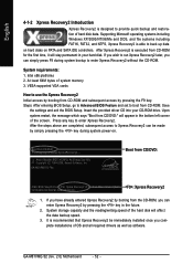
... immediately installed once you can enter Xpress Recovery2 by pressing the key in the bottom left corner of OS and all required drivers as well as software. If you have already entered Xpress Recovery2 by booting from the CD-ROM, you can simply press F9 during system power-on PATA and SATA IDE controllers. GA-M61VME-S2 (rev. 2.0) Motherboard - 52 - Save the settings and exit the BIOS Setup. English...
... immediately installed once you can enter Xpress Recovery2 by pressing the key in the bottom left corner of OS and all required drivers as well as software. If you have already entered Xpress Recovery2 by booting from the CD-ROM, you can simply press F9 during system power-on PATA and SATA IDE controllers. GA-M61VME-S2 (rev. 2.0) Motherboard - 52 - Save the settings and exit the BIOS Setup. English...
Manual
Page 54
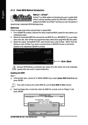
... RAID/AHCI mode or hard drives attached to update BIOS: 1. Q-Flash Utility v2.02 Flash Type/Size SST 25LF040A 512K Keep DMI Data Enable Update BIOS from the hassles of going through complicated BIOS flashing process. Extract the downloaded BIOS files and save the new BIOS file (e.g. Award Modular BIOS v6.00PG, An Energy Star Ally Copyright (C) 1984-2006, Award Software, Inc. b. If you wish to use the UP or DOWN ARROW key to your motherboard model 2. GA-M61VME-S2 F6a . . . . :BIOS Setup/Q-Flash : Xpress Recovery2 : Boot Menu...
... RAID/AHCI mode or hard drives attached to update BIOS: 1. Q-Flash Utility v2.02 Flash Type/Size SST 25LF040A 512K Keep DMI Data Enable Update BIOS from the hassles of going through complicated BIOS flashing process. Extract the downloaded BIOS files and save the new BIOS file (e.g. Award Modular BIOS v6.00PG, An Energy Star Ally Copyright (C) 1984-2006, Award Software, Inc. b. If you wish to use the UP or DOWN ARROW key to your motherboard model 2. GA-M61VME-S2 F6a . . . . :BIOS Setup/Q-Flash : Xpress Recovery2 : Boot Menu...
Manual
Page 56
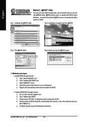
... click "Internet Update" icon b. d. The @BIOS Utility Click "3" Click "Update New BIOS" Click Start/ Programs/ GIGABYTE/@BIOS Fig 4. Methods and steps: I. Click "Update New BIOS" c. GA-M61VME-S2 (rev. 2.0) Motherboard - 56 - Installation Complete and Run @BIOS Select @BIOS item than click Install Fig 3. English Method 2 : @BIOSTM Utility If you do not have a DOS startup disk, we recommend that you use the new @BIOS utility. @BIOS allows users to download the latest version of BIOS. Please select "All Files" in...
... click "Internet Update" icon b. d. The @BIOS Utility Click "3" Click "Update New BIOS" Click Start/ Programs/ GIGABYTE/@BIOS Fig 4. Methods and steps: I. Click "Update New BIOS" c. GA-M61VME-S2 (rev. 2.0) Motherboard - 56 - Installation Complete and Run @BIOS Select @BIOS item than click Install Fig 3. English Method 2 : @BIOSTM Utility If you do not have a DOS startup disk, we recommend that you use the new @BIOS utility. @BIOS allows users to download the latest version of BIOS. Please select "All Files" in...

Manual
Page 59
... RAID with hard disks that NV Serial-ATA 1 under the Integrated Peripherals menu is configured correctly in system BIOS Setup and set NV SATA 1 Primary/Secondary RAID to use for RAID. CMOS Setup Utility-Copyright (C) 1984-2006 Award Software Integrated Peripherals Serial-ATA RAID Config On-Chip IDE Channel0 On-Chip MAC Lan NV Serial-ATA 1 IDE Prefetch Mode USB Memory Type Onboard Audio Function Onboard LAN Boot ROM Onboard Serial Port 1 Onboard Serial Port 2 Onboard Parallel Port Parallel Port Mode x ECP Mode Use DMA On-Chip USB USB Keyboard Support USB Mouse Support Legacy USB Storage...
... RAID with hard disks that NV Serial-ATA 1 under the Integrated Peripherals menu is configured correctly in system BIOS Setup and set NV SATA 1 Primary/Secondary RAID to use for RAID. CMOS Setup Utility-Copyright (C) 1984-2006 Award Software Integrated Peripherals Serial-ATA RAID Config On-Chip IDE Channel0 On-Chip MAC Lan NV Serial-ATA 1 IDE Prefetch Mode USB Memory Type Onboard Audio Function Onboard LAN Boot ROM Onboard Serial Port 1 Onboard Serial Port 2 Onboard Parallel Port Parallel Port Mode x ECP Mode Use DMA On-Chip USB USB Keyboard Support USB Mouse Support Legacy USB Storage...

Manual
Page 60
... Buffer Size Onboard GPU [Auto] [Press Enter] [CDROM] [Hard Disk] [CDROM] [Setup] [Disabled] [Disabled] [PCI Slot] [64M] [Enable If No Ext PEG] Item Help Menu Level : Move Enter: Select F5: Previous Values +/-/PU/PD: Value F10: Save F6: Fail-Safe Defaults Figure 3 ESC: Exit F1: General Help F7: Optimized Defaults Step 3: Save and exit BIOS Setup. CMOS Setup Utility-Copyright (C) 1984-2006 Award Software Advanced BIOS Features AMD K8 Cool&Quiet control Hard Disk Boot Priority First Boot Device Second Boot Device Third Boot Device Password Check HDD S.M.A.R.T.
... Buffer Size Onboard GPU [Auto] [Press Enter] [CDROM] [Hard Disk] [CDROM] [Setup] [Disabled] [Disabled] [PCI Slot] [64M] [Enable If No Ext PEG] Item Help Menu Level : Move Enter: Select F5: Previous Values +/-/PU/PD: Value F10: Save F6: Fail-Safe Defaults Figure 3 ESC: Exit F1: General Help F7: Optimized Defaults Step 3: Save and exit BIOS Setup. CMOS Setup Utility-Copyright (C) 1984-2006 Award Software Advanced BIOS Features AMD K8 Cool&Quiet control Hard Disk Boot Priority First Boot Device Second Boot Device Third Boot Device Password Check HDD S.M.A.R.T.
Manual
Page 64
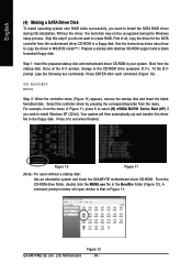
... users without a startup disk: Use an alternative system and insert the GIGABYTE motherboard driver CD-ROM. GA-M61VME-S2 (rev. 2.0) Motherboard Figure 12 - 64 - Once at the A:\> prompt, change to copy the driver in Figure 11. Select the controller driver by pressing the corresponding letter from the startup disk. Without the driver, the hard disk may not be recognized during OS installation. Boot from the menu. Step 1: Insert the prepared startup disk and motherboard driver...
... users without a startup disk: Use an alternative system and insert the GIGABYTE motherboard driver CD-ROM. GA-M61VME-S2 (rev. 2.0) Motherboard Figure 12 - 64 - Once at the A:\> prompt, change to copy the driver in Figure 11. Select the controller driver by pressing the corresponding letter from the startup disk. Without the driver, the hard disk may not be recognized during OS installation. Boot from the menu. Step 1: Insert the prepared startup disk and motherboard driver...
Manual
Page 65
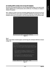
The following mass storage devices(s) * To specify additional SCSI adapters, CD-ROM drives, or special disk controllers for use with the SATA driver. Figure 13 Step 2: When a screen similar to install Windows 2000/XP onto your SATA hard drive with Windows, press ENTER. Windows Setup Setup could not determine the type of some files being loaded before you see the "Press F6 if you need to install a 3rd party SCSI or RAID driver. Appendix Currently, Setup will be...
The following mass storage devices(s) * To specify additional SCSI adapters, CD-ROM drives, or special disk controllers for use with the SATA driver. Figure 13 Step 2: When a screen similar to install Windows 2000/XP onto your SATA hard drive with Windows, press ENTER. Windows Setup Setup could not determine the type of some files being loaded before you see the "Press F6 if you need to install a 3rd party SCSI or RAID driver. Appendix Currently, Setup will be...
Manual
Page 67
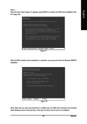
This port of the Setup program prepares Microsoft(R) Windows (R) XP to Setup. To set up Windows XP now, press ENTER. After that hard drive. Enter= Continue R=Repair F3=Exit Figure 18 (Note: Each time you add a new hard drive to a RAID array, the RAID driver will load support for the following mass storage device(s): NVIDIA RAID CLASS DRIVER (required) NVIDIA nForce Storage Controller (required) * To specify additional SCSI adapters, CD-ROM drives, or special disk controllers for use with Windows, including...
This port of the Setup program prepares Microsoft(R) Windows (R) XP to Setup. To set up Windows XP now, press ENTER. After that hard drive. Enter= Continue R=Repair F3=Exit Figure 18 (Note: Each time you add a new hard drive to a RAID array, the RAID driver will load support for the following mass storage device(s): NVIDIA RAID CLASS DRIVER (required) NVIDIA nForce Storage Controller (required) * To specify additional SCSI adapters, CD-ROM drives, or special disk controllers for use with Windows, including...
Manual
Page 74
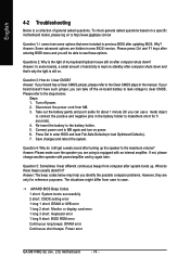
... 4. AWARD BIOS Beep Codes 1 short: System boots successfully 2 short: CMOS setting error 1 long 1 short: DRAM or M/B error 1 long 2 short: Monitor or display card error 1 long 3 short: Keyboard error 1 long 9 short: BIOS ROM error Continuous long beeps: DRAM error Continuous short beeps: Power error GA-M61VME-S2 (rev. 2.0) Motherboard - 74 - English 4-2 Troubleshooting Below is a collection of general asked questions based on a specific motherboard model, please log on -board battery to leak voltage to clear CMOS. Turn off the on to connect the positive and negative pins in new BIOS...
... 4. AWARD BIOS Beep Codes 1 short: System boots successfully 2 short: CMOS setting error 1 long 1 short: DRAM or M/B error 1 long 2 short: Monitor or display card error 1 long 3 short: Keyboard error 1 long 9 short: BIOS ROM error Continuous long beeps: DRAM error Continuous short beeps: Power error GA-M61VME-S2 (rev. 2.0) Motherboard - 74 - English 4-2 Troubleshooting Below is a collection of general asked questions based on a specific motherboard model, please log on -board battery to leak voltage to clear CMOS. Turn off the on to connect the positive and negative pins in new BIOS...


