Manual
Page 1
GA-M61VME-S2 (rev. 2.0) AMD Socket AM2 Processor Motherboard User's Manual Rev. 2002 12ME-M61VMES2-2002R * The WEEE marking on the product indicates this product must not be disposed of with user's other household waste and must be handed over to a designated collection point for the recycling of waste electrical and electronic equipment!! * The WEEE marking applies only in European Union's member states.
GA-M61VME-S2 (rev. 2.0) AMD Socket AM2 Processor Motherboard User's Manual Rev. 2002 12ME-M61VMES2-2002R * The WEEE marking on the product indicates this product must not be disposed of with user's other household waste and must be handed over to a designated collection point for the recycling of waste electrical and electronic equipment!! * The WEEE marking applies only in European Union's member states.
Manual
Page 2
Motherboard GA-M61VME-S2 Sept. 5, 2006 Motherboard GA-M61VME-S2 Sept. 5, 2006
Motherboard GA-M61VME-S2 Sept. 5, 2006 Motherboard GA-M61VME-S2 Sept. 5, 2006
Manual
Page 4
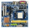
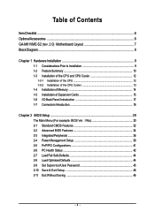
Table of Contents ItemChecklist ...6 OptionalAccessories ...6 GA-M61VME-S2 (rev. 2.0) Motherboard Layout 7 Block Diagram ...8 Chapter 1 Hardware Installation 9 1-1 Considerations Prior to Installation 9 1-2 Feature Summary 10 1-3 Installation of the CPU and CPU Cooler 12 1-3-1 Installation of ...
Table of Contents ItemChecklist ...6 OptionalAccessories ...6 GA-M61VME-S2 (rev. 2.0) Motherboard Layout 7 Block Diagram ...8 Chapter 1 Hardware Installation 9 1-1 Considerations Prior to Installation 9 1-2 Feature Summary 10 1-3 Installation of the CPU and CPU Cooler 12 1-3-1 Installation of ...
Manual
Page 10
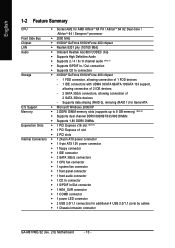
... 3Gb/s connectors, allowing connection of 2 SATA 3Gb/s devices - English 1-2 Feature Summary CPU Š Socket AM2 for additional 4 USB 2.0/1.1 ports by cables Š 1 Chassis Intrusion connector GA-M61VME-S2 (rev. 2.0) Motherboard - 10 -
... 3Gb/s connectors, allowing connection of 2 SATA 3Gb/s devices - English 1-2 Feature Summary CPU Š Socket AM2 for additional 4 USB 2.0/1.1 ports by cables Š 1 Chassis Intrusion connector GA-M61VME-S2 (rev. 2.0) Motherboard - 10 -
Manual
Page 11
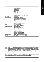
Hardware Installation Windows 64-bit operating system doesn't have such limitation. (Note 3) The GA-M61VME-S2 supports up to PCI Express x1 mode. (please refer to the limitation of Windows 32-bit operating system, when more than 4 GB; English Rear Panel I/O &#...
Hardware Installation Windows 64-bit operating system doesn't have such limitation. (Note 3) The GA-M61VME-S2 supports up to PCI Express x1 mode. (please refer to the limitation of Windows 32-bit operating system, when more than 4 GB; English Rear Panel I/O &#...
Manual
Page 12
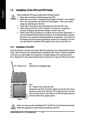
... is not recommended that none are bent. Please add an even layer of the CPU and gently press the metal lever back into their holes. GA-M61VME-S2 (rev. 2.0) Motherboard - 12 - English 1-3 Installation of the pin 1 marking (the small triangle) on the CPU. Please take note of the CPU and CPU Cooler Before...
... is not recommended that none are bent. Please add an even layer of the CPU and gently press the metal lever back into their holes. GA-M61VME-S2 (rev. 2.0) Motherboard - 12 - English 1-3 Installation of the pin 1 marking (the small triangle) on the CPU. Please take note of the CPU and CPU Cooler Before...
Manual
Page 14
... used can be installed in one direction. Reverse the installation steps when you are designed so that the computer power is supported by the motherboard. GA-M61VME-S2 (rev. 2.0) Motherboard - 14 -
... used can be installed in one direction. Reverse the installation steps when you are designed so that the computer power is supported by the motherboard. GA-M61VME-S2 (rev. 2.0) Motherboard - 14 -
Manual
Page 15
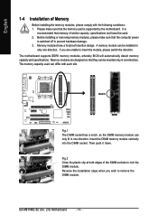
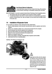
... the slot. 5. Power on the slot. Replace the screw to operate the Dual Channel Technology, follow the guidelines below : 1. English Dual Channel Memory Configuration The GA-M61VME-S2 supports the Dual Channel Technology.
... the slot. 5. Power on the slot. Replace the screw to operate the Dual Channel Technology, follow the guidelines below : 1. English Dual Channel Memory Configuration The GA-M61VME-S2 supports the Dual Channel Technology.
Manual
Page 16
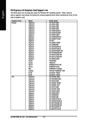
...Nvidia ATi Maker Gigabyte Gigabyte Gigabyte Gigabyte Gigabyte Gigabyte Gigabyte Gigabyte Gigabyte Gigabyte Gigabyte Gigabyte Gigabyte Gigabyte Gigabyte Gigabyte Gigabyte Gigabyte Gigabyte Nvidia Nvidia ASUS ASUS MSI Leadtek ELSA ELSA Gigabyte Gigabyte Gigabyte Gigabyte Gigabyte Gigabyte Gigabyte Gigabyte Gigabyte Gigabyte Gigabyte Gigabyte Gigabyte Gigabyte Gigabyte Gigabyte Gigabyte Model Name GV-...GV-RX85T256V-B GV-RC850T256D-B GV-RX13P256D-RH GV-RX16P256D-RH GV-RX18L256V-B GV-RX18T512V-B GA-M61VME-S2 (rev. 2.0) Motherboard - 16 - English PCI Express x16 Graphics Card Support List The ...
...Nvidia ATi Maker Gigabyte Gigabyte Gigabyte Gigabyte Gigabyte Gigabyte Gigabyte Gigabyte Gigabyte Gigabyte Gigabyte Gigabyte Gigabyte Gigabyte Gigabyte Gigabyte Gigabyte Gigabyte Gigabyte Nvidia Nvidia ASUS ASUS MSI Leadtek ELSA ELSA Gigabyte Gigabyte Gigabyte Gigabyte Gigabyte Gigabyte Gigabyte Gigabyte Gigabyte Gigabyte Gigabyte Gigabyte Gigabyte Gigabyte Gigabyte Gigabyte Gigabyte Model Name GV-...GV-RX85T256V-B GV-RC850T256D-B GV-RX13P256D-RH GV-RX16P256D-RH GV-RX18L256V-B GV-RX18T512V-B GA-M61VME-S2 (rev. 2.0) Motherboard - 16 - English PCI Express x16 Graphics Card Support List The ...
Manual
Page 18
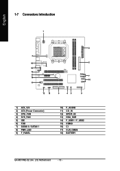
English 1-7 Connectors Introduction 1 2 3 16 5 10 13 17 7 18 14 11 12 15 6 48 9 1) ATX_12V 2) ATX (Power Connector) 3) CPU_FAN 4) SYS_FAN 5) IDE 6) FDD 7) SATAII 0 / SATAII 1 8) PWR_LED 9) F_PANEL 10) F_AUDIO 11) CD_IN 12) SPDIF_IO 13) HDA_SUR 14) F_USB1 / F_USB2 15) COMB 16) CI 17) CLR_CMOS 18) BATTERY GA-M61VME-S2 (rev. 2.0) Motherboard - 18 -
English 1-7 Connectors Introduction 1 2 3 16 5 10 13 17 7 18 14 11 12 15 6 48 9 1) ATX_12V 2) ATX (Power Connector) 3) CPU_FAN 4) SYS_FAN 5) IDE 6) FDD 7) SATAII 0 / SATAII 1 8) PWR_LED 9) F_PANEL 10) F_AUDIO 11) CD_IN 12) SPDIF_IO 13) HDA_SUR 14) F_USB1 / F_USB2 15) COMB 16) CI 17) CLR_CMOS 18) BATTERY GA-M61VME-S2 (rev. 2.0) Motherboard - 18 -
Manual
Page 20
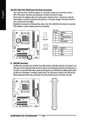
... designed with color-coded power connector wires. Before attaching the IDE cable, please take note of the foolproof groove in the IDE connector. 40 39 2 1 GA-M61VME-S2 (rev. 2.0) Motherboard - 20 - A red power connector wire indicates a positive connection and requires a +12V power voltage. The black connector wire is the ground wire (GND...
... designed with color-coded power connector wires. Before attaching the IDE cable, please take note of the foolproof groove in the IDE connector. 40 39 2 1 GA-M61VME-S2 (rev. 2.0) Motherboard - 20 - A red power connector wire indicates a positive connection and requires a +12V power voltage. The black connector wire is the ground wire (GND...
Manual
Page 22
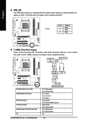
... below. RESRES+ NC HD (IDE Hard Disk Active LED) SPEAK (Speaker Connector) RES (Reset Switch) PW (Power Switch) MSG (Message LED/Power/Sleep LED) NC GA-M61VME-S2 (rev. 2.0) Motherboard Reset Switch IDE Hard Disk Active LED Pin 1: LED anode(+) Pin 2: LED cathode(-) Pin 1: Power Pin 2- Pin 3: NC Pin 4: Data(-) Open: Normal Close...
... below. RESRES+ NC HD (IDE Hard Disk Active LED) SPEAK (Speaker Connector) RES (Reset Switch) PW (Power Switch) MSG (Message LED/Power/Sleep LED) NC GA-M61VME-S2 (rev. 2.0) Motherboard Reset Switch IDE Hard Disk Active LED Pin 1: LED anode(+) Pin 2: LED cathode(-) Pin 1: Power Pin 2- Pin 3: NC Pin 4: Data(-) Open: Normal Close...
Manual
Page 24
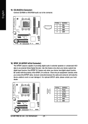
... damage it. Pin No. For optional S/PDIF cable, please contact your local dealer. 51 62 Pin No. 1 2 3 4 5 6 Definition Power No Pin SPDIF SPDIFI GND GND GA-M61VME-S2 (rev. 2.0) Motherboard - 24 - Check the pin assignment carefully while you connect the S/PDIF cable, incorrect connection between the cable and connector will make the device...
... damage it. Pin No. For optional S/PDIF cable, please contact your local dealer. 51 62 Pin No. 1 2 3 4 5 6 Definition Power No Pin SPDIF SPDIFI GND GND GA-M61VME-S2 (rev. 2.0) Motherboard - 24 - Check the pin assignment carefully while you connect the S/PDIF cable, incorrect connection between the cable and connector will make the device...
Manual
Page 26
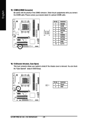
... Open) This 2-pin connector allows your nearest dealer for optional COMB cable. You can check the "Case Opened" status in BIOS Setup. Definition 1 1 Signal 2 GND GA-M61VME-S2 (rev. 2.0) Motherboard - 26 - Please contact your system to detect if the chassis cover is removed.
... Open) This 2-pin connector allows your nearest dealer for optional COMB cable. You can check the "Case Opened" status in BIOS Setup. Definition 1 1 Signal 2 GND GA-M61VME-S2 (rev. 2.0) Motherboard - 26 - Please contact your system to detect if the chassis cover is removed.
Manual
Page 28
English GA-M61VME-S2 (rev. 2.0) Motherboard - 28 -
English GA-M61VME-S2 (rev. 2.0) Motherboard - 28 -
Manual
Page 30
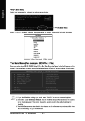
... Ally Copyright (C) 1984-2006, Award Software, Inc. This action makes the system reset to access advanced options. 2. GA-M61VME-S2 (rev. 2.0) Motherboard - 30 - English : Boot Menu Select boot sequence for onboard (or add-on the screen. GA-M61VME-S2 F6a . . . . :BIOS Setup/Q-Flash :Xpress Recovery2 :Boot Menu :Qflash 12/15/2006-NV-MCP61-6A61KG03C-00 :Boot...
... Ally Copyright (C) 1984-2006, Award Software, Inc. This action makes the system reset to access advanced options. 2. GA-M61VME-S2 (rev. 2.0) Motherboard - 30 - English : Boot Menu Select boot sequence for onboard (or add-on the screen. GA-M61VME-S2 F6a . . . . :BIOS Setup/Q-Flash :Xpress Recovery2 :Boot Menu :Qflash 12/15/2006-NV-MCP61-6A61KG03C-00 :Boot...

Manual
Page 32
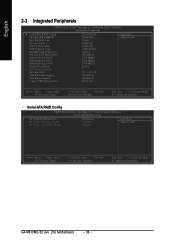
...) IDE Channel 2/3 Master IDE Auto-Detection Press "Enter" to set the access mode for faster system start up . IDE Device Setup. IDE/SATA Device Setup. GA-M61VME-S2 (rev. 2.0) Motherboard - 32 - time clock. IDE Channel 0 Master, Slave IDE HDD Auto-Detection Press "Enter" to select this to select this option for automatic device...
...) IDE Channel 2/3 Master IDE Auto-Detection Press "Enter" to set the access mode for faster system start up . IDE Device Setup. IDE/SATA Device Setup. GA-M61VME-S2 (rev. 2.0) Motherboard - 32 - time clock. IDE Channel 0 Master, Slave IDE HDD Auto-Detection Press "Enter" to select this to select this option for automatic device...
Manual
Page 34
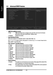
...-HDD. Setup The system will boot, but access to Setup will be denied if the correct password is not entered at the prompt. (Default value) GA-M61VME-S2 (rev. 2.0) Motherboard - 34 - Capability Away Mode Init Display First Frame Buffer Size Onboard GPU [Auto] [Press Enter] [Floppy] [Hard Disk] [CDROM] [Setup] [Disabled] [Disabled] [PEG...
...-HDD. Setup The system will boot, but access to Setup will be denied if the correct password is not entered at the prompt. (Default value) GA-M61VME-S2 (rev. 2.0) Motherboard - 34 - Capability Away Mode Init Display First Frame Buffer Size Onboard GPU [Auto] [Press Enter] [Floppy] [Hard Disk] [CDROM] [Setup] [Disabled] [Disabled] [PEG...
Manual
Page 36
... Level` KLJI: Move Enter: Select F5: Previous Values +/-/PU/PD: Value F10: Save F6: Fail-Safe Defaults ESC: Exit F1: General Help F7: Optimized Defaults GA-M61VME-S2 (rev. 2.0) Motherboard - 36 -
... Level` KLJI: Move Enter: Select F5: Previous Values +/-/PU/PD: Value F10: Save F6: Fail-Safe Defaults ESC: Exit F1: General Help F7: Optimized Defaults GA-M61VME-S2 (rev. 2.0) Motherboard - 36 -
Manual
Page 38
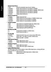
... using onboard USB function. Enabled BIOS will automatically setup the port 2 address. 3F8/IRQ4 2F8/IRQ3 Enable onboard Serial port 2 and address is 3E8/IRQ4. GA-M61VME-S2 (rev. 2.0) Motherboard - 38 -
... using onboard USB function. Enabled BIOS will automatically setup the port 2 address. 3F8/IRQ4 2F8/IRQ3 Enable onboard Serial port 2 and address is 3E8/IRQ4. GA-M61VME-S2 (rev. 2.0) Motherboard - 38 -


