Manual
Page 4
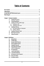
... Contents ...6 OptionalItems ...6 GA-M61PME-S2P Motherboard Layout 7 Block Diagram ...8 Chapter 1 Hardware Installation 9 1-1 Installation Precautions 9 1-2 Product Specifications 10 1-3 Installing the CPU and CPU Cooler 12 1-3-1 Installing the CPU 12 1-3-2 Installing the CPU Cooler 14 1-4 Installing the Memory 15 1-4-1 Dual Channel Memory Configuration 15 1-4-2 Installing a Memory 16 1-5 Installing an Expansion Card 17 1-6 Back Panel Connectors 18...
... Contents ...6 OptionalItems ...6 GA-M61PME-S2P Motherboard Layout 7 Block Diagram ...8 Chapter 1 Hardware Installation 9 1-1 Installation Precautions 9 1-2 Product Specifications 10 1-3 Installing the CPU and CPU Cooler 12 1-3-1 Installing the CPU 12 1-3-2 Installing the CPU Cooler 14 1-4 Installing the Memory 15 1-4-1 Dual Channel Memory Configuration 15 1-4-2 Installing a Memory 16 1-5 Installing an Expansion Card 17 1-6 Back Panel Connectors 18...
Manual
Page 10
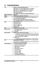
...8 GB of system memory (Note 1) Dual channel memory architecture Support for DDR2 1066/800/667 MHz memory modules (Go to GIGABYTE's website for the latest memory support list.) Realtek ALC883 codec High Definition Audio 2/4/5.1/7.1-channel (Note 2) Support for S/PDIF In/Out...floppy disk drive connector 1 x IDE connector 2 x SATA 3Gb/s connectors 1 x CPU fan header 1 x system fan header 1 x front panel header 1 x front panel audio header 1 x surround/center audio header GA-M61PME-S2P Motherboard - 10 - Support for CD In RTL 8201CL chip (10/100 Mbit) 1 x PCI Express x16 slot, running at x16 1 x ...
...8 GB of system memory (Note 1) Dual channel memory architecture Support for DDR2 1066/800/667 MHz memory modules (Go to GIGABYTE's website for the latest memory support list.) Realtek ALC883 codec High Definition Audio 2/4/5.1/7.1-channel (Note 2) Support for S/PDIF In/Out...floppy disk drive connector 1 x IDE connector 2 x SATA 3Gb/s connectors 1 x CPU fan header 1 x system fan header 1 x front panel header 1 x front panel audio header 1 x surround/center audio header GA-M61PME-S2P Motherboard - 10 - Support for CD In RTL 8201CL chip (10/100 Mbit) 1 x PCI Express x16 slot, running at x16 1 x ...
Manual
Page 11
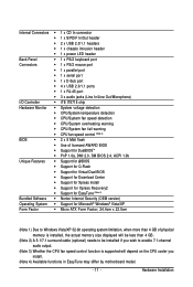
Internal Connectors 1 x CD In connector 1 x S/PDIF In/Out header 2 x USB 2.0/1.1 headers 1 x chassis intrusion header 1 x power LED header Back Panel 1 x PS/2 keyboard port Connectors 1 x PS/2 mouse port 1 x parallel port 1 x serial port 1 x D-Sub port 4 x USB 2.0/1.1 ports 1 x RJ-45 port &#...
Internal Connectors 1 x CD In connector 1 x S/PDIF In/Out header 2 x USB 2.0/1.1 headers 1 x chassis intrusion header 1 x power LED header Back Panel 1 x PS/2 keyboard port Connectors 1 x PS/2 mouse port 1 x parallel port 1 x serial port 1 x D-Sub port 4 x USB 2.0/1.1 ports 1 x RJ-45 port &#...
Manual
Page 17
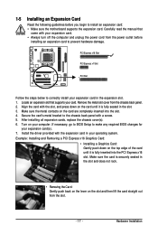
... expansion card. After installing all expansion cards, replace the chassis cover(s). 6. Hardware Installation Secure the card's metal bracket to the chassis back panel with your computer. Turn on the top edge of the card until it is securely seated in your card. PCI Express x16 Slot PCI ...with the slot, and press down on your expansion card. • Always turn off the computer and unplug the power cord from the chassis back panel. 2. Locate an expansion slot that came with a screw. 5. Align the card with the expansion card in the slot and does not rock. &#...
... expansion card. After installing all expansion cards, replace the chassis cover(s). 6. Hardware Installation Secure the card's metal bracket to the chassis back panel with your computer. Turn on the top edge of the card until it is securely seated in your card. PCI Express x16 Slot PCI ...with the slot, and press down on your expansion card. • Always turn off the computer and unplug the power cord from the chassis back panel. 2. Locate an expansion slot that came with a screw. 5. Align the card with the expansion card in the slot and does not rock. &#...
Manual
Page 18
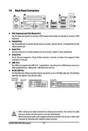
... or receiving is also called a printer port. GA-M61PME-S2P Motherboard - 18 - Use this port. The following describes the states of the LAN port LEDs. The parallel port is occurring LAN Port • When removing the cable connected to a back panel connector, first remove the cable from your device... and then remove it from the connector. USB Port The USB port supports the USB 2.0/1.1 specification. 1-6 Back Panel Connectors PS/2 Keyboard and PS/2 Mouse Port Use the upper port (green) to connect a PS/2 mouse and the lower port (purple) to...
... or receiving is also called a printer port. GA-M61PME-S2P Motherboard - 18 - Use this port. The following describes the states of the LAN port LEDs. The parallel port is occurring LAN Port • When removing the cable connected to a back panel connector, first remove the cable from your device... and then remove it from the connector. USB Port The USB port supports the USB 2.0/1.1 specification. 1-6 Back Panel Connectors PS/2 Keyboard and PS/2 Mouse Port Use the upper port (green) to connect a PS/2 mouse and the lower port (purple) to...
Manual
Page 25
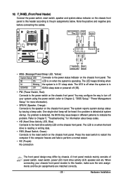
...(S5). • PW (Power Switch, Red): Connects to the power switch on the chassis front panel. RESRES+ NC Hard Drive Activity LED Reset Switch • MSG (Message/Power/Sleep LED, Yellow): ...System Status LED Connects to the power status indicator on the chassis front panel. The LED keeps blinking when S1 Blinking the system is detected, the BIOS may issue beeps in S1...writing data. • RES (Reset Switch, Green): Connects to the reset switch on the chassis front panel. You may differ by issuing a beep code. The LED is on when the hard drive is in...
...(S5). • PW (Power Switch, Red): Connects to the power switch on the chassis front panel. RESRES+ NC Hard Drive Activity LED Reset Switch • MSG (Message/Power/Sleep LED, Yellow): ...System Status LED Connects to the power status indicator on the chassis front panel. The LED keeps blinking when S1 Blinking the system is detected, the BIOS may issue beeps in S1...writing data. • RES (Reset Switch, Green): Connects to the reset switch on the chassis front panel. You may differ by issuing a beep code. The LED is on when the hard drive is in...
Manual
Page 26
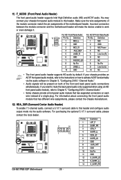
.... 1 2 3 4 5 6 7 8 9 10 11 12 13 14 Definition LEF_P SURR_RR CEN_P SURR_LL CEN_JD SURR_JD GND -SUR_DET GND No Pin GND S_SURR_JD S_SURR_LL S_SURR_RR GA-M61PME-S2P Motherboard - 26 - For information about connecting the front panel audio module that has separated connectors on how to activate AC'97 functioninality via the audio software. You may connect your...
.... 1 2 3 4 5 6 7 8 9 10 11 12 13 14 Definition LEF_P SURR_RR CEN_P SURR_LL CEN_JD SURR_JD GND -SUR_DET GND No Pin GND S_SURR_JD S_SURR_LL S_SURR_RR GA-M61PME-S2P Motherboard - 26 - For information about connecting the front panel audio module that has separated connectors on how to activate AC'97 functioninality via the audio software. You may connect your...
Manual
Page 63
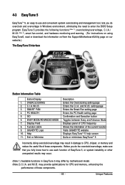
... PC Health setting page Confirmation and Execution button Toggles between Easy and Advance Mode Displays panel of CPU frequency Shows the information of the current function Visits GIGABYTE website Displays EasyTuneTM 5 help screen Quits or minimizes EasyTuneTM 5 Incorrectly doing overclock/overvoltage...download the information on/from the Support\Motherboard\Utility page on our website.) The EasyTune 5 Interface Button Information Table Button/Display 1. GIGABYTE Logo 10. and M.I .A. 4-3 EasyTune 5 EasyTuneTM 5, an easy-to-use and convenient system overclocking and management tool, lets ...
... PC Health setting page Confirmation and Execution button Toggles between Easy and Advance Mode Displays panel of CPU frequency Shows the information of the current function Visits GIGABYTE website Displays EasyTuneTM 5 help screen Quits or minimizes EasyTuneTM 5 Incorrectly doing overclock/overvoltage...download the information on/from the Support\Motherboard\Utility page on our website.) The EasyTune 5 Interface Button Information Table Button/Display 1. GIGABYTE Logo 10. and M.I .A. 4-3 EasyTune 5 EasyTuneTM 5, an easy-to-use and convenient system overclocking and management tool, lets ...
Manual
Page 72
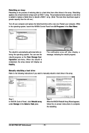
The rebuild is completed, the array status will also display a message, indicating the rebuild progress. GA-M61PME-S2P Motherboard - 72 - While in the operating system, launch the NVIDIA Control Panel from other drives in the array. The notification area will display as RAID 1 array. Step 2: When the NVIDIA ... is the process of restoring data to a hard drive from All Programs in the Select a Task pane. Step 1: In NVIDIA Control Panel, click Rebuild array under Storage in the Start Menu. Restart your computer and replace the failed hard drive with a new one. You ...
The rebuild is completed, the array status will also display a message, indicating the rebuild progress. GA-M61PME-S2P Motherboard - 72 - While in the operating system, launch the NVIDIA Control Panel from other drives in the array. The notification area will display as RAID 1 array. Step 2: When the NVIDIA ... is the process of restoring data to a hard drive from All Programs in the Select a Task pane. Step 1: In NVIDIA Control Panel, click Rebuild array under Storage in the Start Menu. Restart your computer and replace the failed hard drive with a new one. You ...
Manual
Page 73
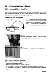
.... 5-2 Configuring Audio Input and Output 5-2-1 Configuring 2/4/5.1/7.1-Channel Audio The motherboard provides three audio jacks on your motherboard. Step 2: Secure the bracket to the chassis back panel with a screw. (Note) 2/4/5.1/7.1 Channel Audio Configurations: Refer to set up a multi-channel audio system and keep Line in and Mic in functionalities at the end...
.... 5-2 Configuring Audio Input and Output 5-2-1 Configuring 2/4/5.1/7.1-Channel Audio The motherboard provides three audio jacks on your motherboard. Step 2: Secure the bracket to the chassis back panel with a screw. (Note) 2/4/5.1/7.1 Channel Audio Configurations: Refer to set up a multi-channel audio system and keep Line in and Mic in functionalities at the end...
Manual
Page 74
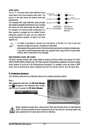
...the audio driver, the HD Audio Manager icon will be simultaneously processed. GA-M61PME-S2P Motherboard - 74 - Line In Line Out (Front Speaker Out) Mic In Audio Jacks on both of the front and back panel audio connections simultaneously. Audio Jacks on the next page. If you can ... Internet, and etc. Audio Jacks: The 5.1/7.1 surround cable adds additional three audio jacks to be present on the Motherboard Back Panel • To install a microphone, connect your operating system has been updated with the latest Service Pack for each jack through the audio ...
...the audio driver, the HD Audio Manager icon will be simultaneously processed. GA-M61PME-S2P Motherboard - 74 - Line In Line Out (Front Speaker Out) Mic In Audio Jacks on both of the front and back panel audio connections simultaneously. Audio Jacks on the next page. If you can ... Internet, and etc. Audio Jacks: The 5.1/7.1 surround cable adds additional three audio jacks to be present on the Motherboard Back Panel • To install a microphone, connect your operating system has been updated with the latest Service Pack for each jack through the audio ...

Manual
Page 75
... Sound Effect: You may configure an audio environment on the Speaker Configuration tab to open the Device advanced settings dialog box. Muting the Back Panel Audio (For HD Audio Only): Click Device advanced settings on the top right corner on the Sound Effects tab. Select the device according to... set up. Then the speaker setup is dialog box appears. On the Connector Settings dialog box, select the Disable front panel jack detection check box. Select the Mute the rear output device, when a front headphone plugged in check box. Click OK to activate the ...
... Sound Effect: You may configure an audio environment on the Speaker Configuration tab to open the Device advanced settings dialog box. Muting the Back Panel Audio (For HD Audio Only): Click Device advanced settings on the top right corner on the Sound Effects tab. Select the device according to... set up. Then the speaker setup is dialog box appears. On the Connector Settings dialog box, select the Disable front panel jack detection check box. Select the Mute the rear output device, when a front headphone plugged in check box. Click OK to activate the ...

Manual
Page 76
GA-M61PME-S2P Motherboard - 76 - A. Optical S/PDIF Out Coaxial S/PDIFOut Optical S/PDIF In Coaxial S/PDIFIn S/PDIF in: The S/PDIF...external decoder (or you to input digital audio signals to the computer for decoding to the SPDIF_IO header on the motherboard back panel). S/PDIF out: The S/PDIF out jacks can transmit audio signals to an external decoder for audio processing. Installing the ...S/PDIF out connector on your motherboard. Step 2: Secure the metal bracket to the chassis back panel with a screw. (Note) The actual locations of the cable to get the best audio quality.
GA-M61PME-S2P Motherboard - 76 - A. Optical S/PDIF Out Coaxial S/PDIFOut Optical S/PDIF In Coaxial S/PDIFIn S/PDIF in: The S/PDIF...external decoder (or you to input digital audio signals to the computer for decoding to the SPDIF_IO header on the motherboard back panel). S/PDIF out: The S/PDIF out jacks can transmit audio signals to an external decoder for audio processing. Installing the ...S/PDIF out connector on your motherboard. Step 2: Secure the metal bracket to the chassis back panel with a screw. (Note) The actual locations of the cable to get the best audio quality.
Manual
Page 78
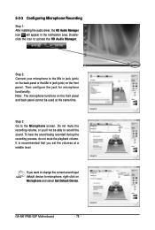
Note: The microphone functions on the front panel and back panel cannot be able to the Mic in jack (pink) on the back panel or the Mic in the notification area. Do not mute the recording volume, or you want to change the current sound input ...default device to microphone, right-click on the front panel. Step 2: Connect your microphone to record the sound. Step 3: Go to access the HD Audio Manager. If you 'll not be used at a middle level. GA-M61PME-S2P Motherboard - 78 - 5-2-3 Configuring Microphone Recording Step 1: After installing the audio...
Note: The microphone functions on the front panel and back panel cannot be able to the Mic in jack (pink) on the back panel or the Mic in the notification area. Do not mute the recording volume, or you want to change the current sound input ...default device to microphone, right-click on the front panel. Step 2: Connect your microphone to record the sound. Step 3: Go to access the HD Audio Manager. If you 'll not be used at a middle level. GA-M61PME-S2P Motherboard - 78 - 5-2-3 Configuring Microphone Recording Step 1: After installing the audio...


