Manual
Page 4
Table of Contents Box Contents ...6 OptionalItems...6 GA-M52L-S3P Motherboard Layout 7 Block Diagram...8 Chapter 1 Hardware Installation 9 1-1 Installation Precautions 9 1-2 Product Specifications 10 1-3 Installing the CPU and CPU Cooler 12 1-3-1 Installing the CPU 12 1-3-2 Installing the CPU Cooler 14 1-4 Installing the Memory 15 1-4-1 Dual Channel Memory Configuration 15 1-4-2 Installing a Memory 16 1-5 Installing an Expansion Card 17 1-6 Back Panel Connectors 18...
Table of Contents Box Contents ...6 OptionalItems...6 GA-M52L-S3P Motherboard Layout 7 Block Diagram...8 Chapter 1 Hardware Installation 9 1-1 Installation Precautions 9 1-2 Product Specifications 10 1-3 Installing the CPU and CPU Cooler 12 1-3-1 Installing the CPU 12 1-3-2 Installing the CPU Cooler 14 1-4 Installing the Memory 15 1-4-1 Dual Channel Memory Configuration 15 1-4-2 Installing a Memory 16 1-5 Installing an Expansion Card 17 1-6 Back Panel Connectors 18...
Manual
Page 8
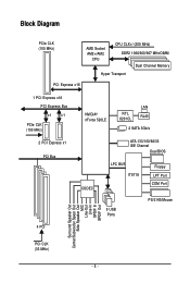
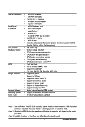
Block Diagram PCIe CLK (100 MHz) AMD Socket AM2+/AM2 CPU CPU CLK+/-(200 MHz) DDR2 1066/800/667 MHz DIMM Dual Channel Memory Hyper Transport PCI Express x16 1 PCI Express x16 PCI Express Bus x1 x1 PCIe CLK (100 MHz) 2 PCI Express x1 PCI Bus 4 PCI NVIDIA® nForce 520LE RTL 8201CL LAN RJ45 2 SATA 3Gb/s ATA-133/100/66/33 IDE Channel Dual BIOS CODEC LPC BUS IT8718 Floppy LPT Port COM Port 8 USB Ports PS/2 KB/Mouse Surround Speaker Out Center/Subwoofer Spear Out Side Speaker Out MIC Line-Out Line-In SPDIF In SPDIF Out PCI CLK (33 MHz) - 8 -
Block Diagram PCIe CLK (100 MHz) AMD Socket AM2+/AM2 CPU CPU CLK+/-(200 MHz) DDR2 1066/800/667 MHz DIMM Dual Channel Memory Hyper Transport PCI Express x16 1 PCI Express x16 PCI Express Bus x1 x1 PCIe CLK (100 MHz) 2 PCI Express x1 PCI Bus 4 PCI NVIDIA® nForce 520LE RTL 8201CL LAN RJ45 2 SATA 3Gb/s ATA-133/100/66/33 IDE Channel Dual BIOS CODEC LPC BUS IT8718 Floppy LPT Port COM Port 8 USB Ports PS/2 KB/Mouse Surround Speaker Out Center/Subwoofer Spear Out Side Speaker Out MIC Line-Out Line-In SPDIF In SPDIF Out PCI CLK (33 MHz) - 8 -
Manual
Page 9
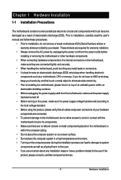
... other hardware components. • When connecting hardware components to the internal connectors on the computer power during the installation process can become damaged as a motherboard, CPU or memory. Chapter 1 Hardware Installation 1-1 Installation Precautions The motherboard contains numerous delicate electronic circuits and components which can lead to damage to system components as...
... other hardware components. • When connecting hardware components to the internal connectors on the computer power during the installation process can become damaged as a motherboard, CPU or memory. Chapter 1 Hardware Installation 1-1 Installation Precautions The motherboard contains numerous delicate electronic circuits and components which can lead to damage to system components as...
Manual
Page 10
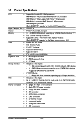
...AMD PhenomTM X3 processor/AMD AthlonTM X2 processor/ AMD AthlonTM processor/AMD SempronTM X2 processor/ AMD SempronTM processor (Go to GIGABYTE's website for the latest CPU support list.) 2000 MT/s NVIDIA® nForce 520LE chipset 4 x 1.8V DDR2 DIMM sockets supporting up to 16 ...ATX 12V power connector 1 x floppy disk drive connector 1 x IDE connector 2 x SATA 3Gb/s connectors 1 x CPU fan header 1 x system fan header 1 x front panel header 1 x front panel audio header 1 x CD In connector GA-M52L-S3P Motherboard - 10 - Support for CD In RTL 8201CL chip (10/100 Mbit) 1 x PCI Express x16 slot ...
...AMD PhenomTM X3 processor/AMD AthlonTM X2 processor/ AMD AthlonTM processor/AMD SempronTM X2 processor/ AMD SempronTM processor (Go to GIGABYTE's website for the latest CPU support list.) 2000 MT/s NVIDIA® nForce 520LE chipset 4 x 1.8V DDR2 DIMM sockets supporting up to 16 ...ATX 12V power connector 1 x floppy disk drive connector 1 x IDE connector 2 x SATA 3Gb/s connectors 1 x CPU fan header 1 x system fan header 1 x front panel header 1 x front panel audio header 1 x CD In connector GA-M52L-S3P Motherboard - 10 - Support for CD In RTL 8201CL chip (10/100 Mbit) 1 x PCI Express x16 slot ...
Manual
Page 11
... Controller iTE IT8718 chip Hardware Monitor System voltage detection CPU/System temperature detection CPU/System fan speed detection CPU/System overheating warning CPU/System fan fail warning CPU/System fan speed control (Note 2) BIOS 2 x 8 Mbit flash ...4 GB of physical memory is installed, the actual memory size displayed will be less than 4 GB. (Note 2) Whether the CPU/System fan speed control function is supported will depend on the cooler you install. (Note 3) Available functions in EasyTune may differ ...
... Controller iTE IT8718 chip Hardware Monitor System voltage detection CPU/System temperature detection CPU/System fan speed detection CPU/System overheating warning CPU/System fan fail warning CPU/System fan speed control (Note 2) BIOS 2 x 8 Mbit flash ...4 GB of physical memory is installed, the actual memory size displayed will be less than 4 GB. (Note 2) Whether the CPU/System fan speed control function is supported will depend on the cooler you install. (Note 3) Available functions in EasyTune may differ ...
Manual
Page 12
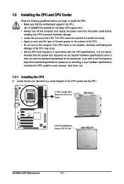
... is not installed, otherwise overheating and damage of the Socket AM2 Socket A Small Triangle Marking Denotes CPU Pin One AM2+/AM2 CPU GA-M52L-S3P Motherboard - 12 - If you begin to install the CPU: • Make sure that the system bus frequency be inserted if oriented incorrectly. • Apply... meet the standard requirements for the latest CPU support list.) • Always turn on the computer if the CPU cooler is not recom- Locate the pin one of the CPU socket and the CPU. mended that the motherboard supports the CPU. (Go to GIGABYTE's website for the peripherals.
... is not installed, otherwise overheating and damage of the Socket AM2 Socket A Small Triangle Marking Denotes CPU Pin One AM2+/AM2 CPU GA-M52L-S3P Motherboard - 12 - If you begin to install the CPU: • Make sure that the system bus frequency be inserted if oriented incorrectly. • Apply... meet the standard requirements for the latest CPU support list.) • Always turn on the computer if the CPU cooler is not recom- Locate the pin one of the CPU socket and the CPU. mended that the motherboard supports the CPU. (Go to GIGABYTE's website for the peripherals.
Manual
Page 13
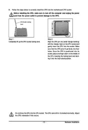
... the steps below to the CPU. CPU Socket Locking Lever Step 1: Completely lift up the CPU socket locking lever. Do not force the CPU into the motherboard CPU socket. Adjust the CPU orientation if this occurs. - 13 - Make sure that the CPU pins fit perfectly into the fully locked position. B. Step 2: Align the CPU pin one finger down...
... the steps below to the CPU. CPU Socket Locking Lever Step 1: Completely lift up the CPU socket locking lever. Do not force the CPU into the motherboard CPU socket. Adjust the CPU orientation if this occurs. - 13 - Make sure that the CPU pins fit perfectly into the fully locked position. B. Step 2: Align the CPU pin one finger down...
Manual
Page 14
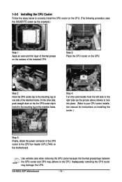
... an even and thin layer of thermal grease on the surface of the installed CPU. Use extreme care when removing the CPU cooler because the thermal grease/tape between the CPU cooler and CPU may damage the CPU. GA-M52L-S3P Motherboard - 14 - On the other side, push straight down on the the... on one side of the retention frame. Inadequately removing the CPU cooler may adhere to the CPU. 1-3-2 Installing the CPU Cooler Follow the steps below to correctly install the CPU cooler on the CPU. (The following procedure uses the GIGABYTE cooler as the picture above shows) to lock into place...
... an even and thin layer of thermal grease on the surface of the installed CPU. Use extreme care when removing the CPU cooler because the thermal grease/tape between the CPU cooler and CPU may damage the CPU. GA-M52L-S3P Motherboard - 14 - On the other side, push straight down on the the... on one side of the retention frame. Inadequately removing the CPU cooler may adhere to the CPU. 1-3-2 Installing the CPU Cooler Follow the steps below to correctly install the CPU cooler on the CPU. (The following procedure uses the GIGABYTE cooler as the picture above shows) to lock into place...
Manual
Page 15
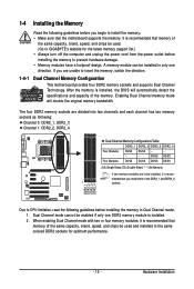
... memory of the same capacity, brand, speed, and chips be enabled if only one direction. Dual Channel mode cannot be used . (Go to GIGABYTE's website for optimum performance. - 15 - When enabling Dual Channel mode with two or four memory modules, it is recommended that the motherboard supports ...Four Modules DS/SS DS/SS DS/SS DS/SS (SS=Single-Sided, DS=Double-Sided, "- -"=No Memory) If two memory modules are to CPU limitation, read the following : Channel 0: DDR2_1, DDR2_3 Channel 1: DDR2_2, DDR2_4 Dual Channel Memory Configurations Table DDR2_1 DDR2_2 DDR2_3 DDR2_4 Two Modules DS/...
... memory of the same capacity, brand, speed, and chips be enabled if only one direction. Dual Channel mode cannot be used . (Go to GIGABYTE's website for optimum performance. - 15 - When enabling Dual Channel mode with two or four memory modules, it is recommended that the motherboard supports ...Four Modules DS/SS DS/SS DS/SS DS/SS (SS=Single-Sided, DS=Double-Sided, "- -"=No Memory) If two memory modules are to CPU limitation, read the following : Channel 0: DDR2_1, DDR2_3 Channel 1: DDR2_2, DDR2_4 Dual Channel Memory Configurations Table DDR2_1 DDR2_2 DDR2_3 DDR2_4 Two Modules DS/...
Manual
Page 21
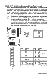
... the power supply is compatible with power supplies with 2x10 power connectors. The power connector possesses a foolproof design. Connect the power supply cable to the CPU. If a power supply is used that can withstand high power consumption be used (500W or greater). When using a 2x10 power supply. 2 1 4 3 ATX_12V ATX_12V: Pin No...
... the power supply is compatible with power supplies with 2x10 power connectors. The power connector possesses a foolproof design. Connect the power supply cable to the CPU. If a power supply is used that can withstand high power consumption be used (500W or greater). When using a 2x10 power supply. 2 1 4 3 ATX_12V ATX_12V: Pin No...
Manual
Page 22
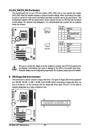
... result in the correct orientation (the black connector wire is the ground wire). The motherboard supports CPU fan speed control, which requires the use of different color. 33 1 34 2 GA-M52L-S3P Motherboard - 22 - Before connecting a floppy disk drive, be installed inside the chassis. Overheating may...not place a jumper cap on the headers. 5) FDD (Floppy Disk Drive Connector) This connector is typically designated by a stripe of a CPU fan with fan speed control design. The types of the connector and the floppy disk drive cable. 3/4) CPU_FAN/SYS_FAN (Fan Headers) The ...
... result in the correct orientation (the black connector wire is the ground wire). The motherboard supports CPU fan speed control, which requires the use of different color. 33 1 34 2 GA-M52L-S3P Motherboard - 22 - Before connecting a floppy disk drive, be installed inside the chassis. Overheating may...not place a jumper cap on the headers. 5) FDD (Floppy Disk Drive Connector) This connector is typically designated by a stripe of a CPU fan with fan speed control design. The types of the connector and the floppy disk drive cable. 3/4) CPU_FAN/SYS_FAN (Fan Headers) The ...
Manual
Page 33
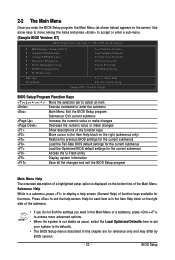
... Fail-Safe Defaults Load Optimized Defaults Set Supervisor Password Set User Password Save & Exit Setup Exit Without Saving Select Item F10: Save & Exit Setup Change CPU's Clock & Voltage BIOS Setup Program Function Keys Move the selection bar to select an item Execute command or enter the submenu Main Menu: Exit the...
... Fail-Safe Defaults Load Optimized Defaults Set Supervisor Password Set User Password Save & Exit Setup Exit Without Saving Select Item F10: Save & Exit Setup Change CPU's Clock & Voltage BIOS Setup Program Function Keys Move the selection bar to select an item Execute command or enter the submenu Main Menu: Exit the...
Manual
Page 34
... but not to make changes in the BIOS Setup program to the CMOS and exit BIOS Setup. (Pressing can also carry out this task.) GA-M52L-S3P Motherboard - 34 - It allows you to restrict access to the system and BIOS Setup. It allows you to restrict access to the system ...Configurations Use this menu to configure the system's PCI & PnP resources. PC Health Status Use this menu to see information about autodetected system/CPU temperature, system voltage and fan speed, etc. Load Fail-Safe Defaults Fail-Safe defaults are factory settings for the most stable, minimal-...
... but not to make changes in the BIOS Setup program to the CMOS and exit BIOS Setup. (Pressing can also carry out this task.) GA-M52L-S3P Motherboard - 34 - It allows you to restrict access to the system and BIOS Setup. It allows you to restrict access to the system ...Configurations Use this menu to configure the system's PCI & PnP resources. PC Health Status Use this menu to see information about autodetected system/CPU temperature, system voltage and fan speed, etc. Load Fail-Safe Defaults Fail-Safe defaults are factory settings for the most stable, minimal-...

Manual
Page 35
...CMOS Setup Utility-Copyright (C) 1984-2008 Award Software MB Intelligent Tweaker(M.I.T.) CPU Frequency (MHz) PCIE Clock (MHz) CPU Clock Ratio CPU NorthBridge Freq. (Note) CPU NB VID Control (Note) CPU Voltage Control CPU HT-Link Voltage Chipset Voltage Control DDR2 Voltage Control Normal CPU Vcore [200] [100] [Auto] [Auto] [Normal] [Normal... result in accordance with the overclock/overvoltage settings you made is from 100 MHz to 200 MHz. (Default: 100) CPU Clock Ratio Allows you to set the PCIe clock frequency. The adjustable range is highly recommended that supports this occurs, ...
...CMOS Setup Utility-Copyright (C) 1984-2008 Award Software MB Intelligent Tweaker(M.I.T.) CPU Frequency (MHz) PCIE Clock (MHz) CPU Clock Ratio CPU NorthBridge Freq. (Note) CPU NB VID Control (Note) CPU Voltage Control CPU HT-Link Voltage Chipset Voltage Control DDR2 Voltage Control Normal CPU Vcore [200] [100] [Auto] [Auto] [Normal] [Normal... result in accordance with the overclock/overvoltage settings you made is from 100 MHz to 200 MHz. (Default: 100) CPU Clock Ratio Allows you to set the PCIe clock frequency. The adjustable range is highly recommended that supports this occurs, ...
Manual
Page 36
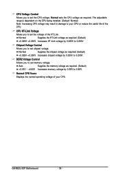
... chipset voltage by 0.05V to 0.60V. GA-M52L-S3P Motherboard - 36 - Normal Supplies the HT-Link voltage as required. The adjustable range is dependent on the CPU being installed. (Default: Normal) Note: Increasing CPU voltage may result in damage to your CPU or reduce the useful life of your CPU. CPU Voltage Control Allows you to set memory...
... chipset voltage by 0.05V to 0.60V. GA-M52L-S3P Motherboard - 36 - Normal Supplies the HT-Link voltage as required. The adjustable range is dependent on the CPU being installed. (Default: Normal) Note: Increasing CPU voltage may result in damage to your CPU or reduce the useful life of your CPU. CPU Voltage Control Allows you to set memory...
Manual
Page 39
... or disables the Patch AMD TLB Erratum function. (Default: Enabled) AMD K8 Cool&Quiet control Auto Lets the AMD Cool'n'Quiet driver dynamically adjust the CPU clock and VID to reduce heat output from your computer and its power consumption. (Default) Disabled Disables this feature. - 39 - Options are: Floppy, LS120, Hard... Disk, CDROM, ZIP, USB-FDD, USB-ZIP, USB-CDROM, USB-HDD, Legacy LAN, Disabled. (Note) This item is present only if you install a CPU that supports this function.
... or disables the Patch AMD TLB Erratum function. (Default: Enabled) AMD K8 Cool&Quiet control Auto Lets the AMD Cool'n'Quiet driver dynamically adjust the CPU clock and VID to reduce heat output from your computer and its power consumption. (Default) Disabled Disables this feature. - 39 - Options are: Floppy, LS120, Hard... Disk, CDROM, ZIP, USB-FDD, USB-ZIP, USB-CDROM, USB-HDD, Legacy LAN, Disabled. (Note) This item is present only if you install a CPU that supports this function.
Manual
Page 47
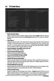
... Check the fan condition or fan connection when this field will show "Yes", otherwise it will emit warning sound. When system/CPU temperature exceeds the threshold, BIOS will show "No" at next boot. (Default: Disabled) Case Opened Displays the detection status of... the motherboard CI header. Enabled clears the record of previous chassis intrusion status. Current CPU/SYSTEM FAN Speed (RPM) Displays current CPU/system fan speed. Current System/CPU Temperature Displays current system/CPU temperature. Options are: Disabled (default), 60oC/140oF, 70oC/158oF, 80oC/176oF, 90oC...
... Check the fan condition or fan connection when this field will show "Yes", otherwise it will emit warning sound. When system/CPU temperature exceeds the threshold, BIOS will show "No" at next boot. (Default: Disabled) Case Opened Displays the detection status of... the motherboard CI header. Enabled clears the record of previous chassis intrusion status. Current CPU/SYSTEM FAN Speed (RPM) Displays current CPU/system fan speed. Current System/CPU Temperature Displays current system/CPU temperature. Options are: Disabled (default), 60oC/140oF, 70oC/158oF, 80oC/176oF, 90oC...
Manual
Page 48
...at different speed according to run at full speed. (Default: Enabled) GA-M52L-S3P Motherboard - 48 - You can adjust the fan speed with EasyTune based on system requirements. PWM Sets PWM mode for a 3-pin CPU fan. CPU Smart FAN Mode Specifies how to Enabled. Auto Lets BIOS autodetect the ...type of CPU fan installed and sets the optimal CPU fan control mode. (Default) Voltage Sets Voltage mode for a 4-pin CPU fan. System Smart FAN Control Enables or ...
...at different speed according to run at full speed. (Default: Enabled) GA-M52L-S3P Motherboard - 48 - You can adjust the fan speed with EasyTune based on system requirements. PWM Sets PWM mode for a 3-pin CPU fan. CPU Smart FAN Mode Specifies how to Enabled. Auto Lets BIOS autodetect the ...type of CPU fan installed and sets the optimal CPU fan control mode. (Default) Voltage Sets Voltage mode for a 4-pin CPU fan. System Smart FAN Control Enables or ...
Manual
Page 65
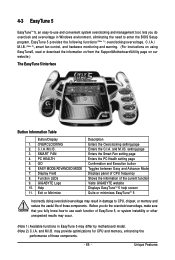
... setting page Enters the PC Health setting page Confirmation and Execution button Toggles between Easy and Advance Mode Displays panel of CPU frequency Shows the information of the current function Visits GIGABYTE website Displays EasyTuneTM 5 help screen Quits or minimizes EasyTuneTM 5 Incorrectly doing overclock/overvoltage may result in Windows environment, eliminating the...
... setting page Enters the PC Health setting page Confirmation and Execution button Toggles between Easy and Advance Mode Displays panel of CPU frequency Shows the information of the current function Visits GIGABYTE website Displays EasyTuneTM 5 help screen Quits or minimizes EasyTuneTM 5 Incorrectly doing overclock/overvoltage may result in Windows environment, eliminating the...
Manual
Page 83
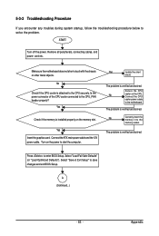
...Defaults" (or "Load Optimized Defaults"). Yes Check if the memory is installed properly on the CPU. The problem is verified and solved. The problem is attached to enter BIOS Setup. Secure the CPU No cooler on the memory slot. No Correctly insert the memory into the memory socket. Remove... to solve the problem. Connect the ATX main power cable and the 12V power cable. Press to the CPU securely. No Check if the CPU cooler is verified and solved. Connect the CPU cooler power cable to save changes and exit BIOS Setup. Appendix Select "Save & Exit Setup" to the...
...Defaults" (or "Load Optimized Defaults"). Yes Check if the memory is installed properly on the CPU. The problem is verified and solved. The problem is attached to enter BIOS Setup. Secure the CPU No cooler on the memory slot. No Correctly insert the memory into the memory socket. Remove... to solve the problem. Connect the ATX main power cable and the 12V power cable. Press to the CPU securely. No Check if the CPU cooler is verified and solved. Connect the CPU cooler power cable to save changes and exit BIOS Setup. Appendix Select "Save & Exit Setup" to the...


